MKS 937B Series Operation And Maintenance Manual
Vacuum system controller
Hide thumbs
Also See for 937B Series:
- Operation and maintenance manual (120 pages) ,
- Operation and maintenance manual (131 pages)

Related Manuals for MKS 937B Series


Summary of Contents for MKS 937B Series
- Page 1 Series 937B Vacuum System Controller Operation and Maintenance Manual Instruction Manual p/n: 100016467 Rev F, August 2020...
-
Page 2: Table Of Contents
Serial Communication Response Format ........................15 Feature, Control Locations and Dimensions .................. 16 Typical Applications for the Series 937B Controller ............... 18 MKS Series 937B Vacuum System Controller ................19 Operating the Series 937B Controller..................... 21 Power ................................. 21 Front Panel Control Lock ..........................21 Front Panel Display ............................ - Page 3 10.4 Mounting the Controller ..........................89 10.5 AC Power Cord ............................90 11 Maintenance and Service of MKS Vacuum Sensors..............91 11.1 422, 423 and 431 Cold Cathode Sensors ....................91 11.2 Maintenance of Series 431/422 Cold Cathode Sensor ................92 11.2.1...
- Page 4 Visit our website at: www.mksinst.com Warranty Information MKS Instruments, Inc. provides an eighteen (18) month warranty from the date of shipment for new MKS products. The MKS Instruments, Inc. general terms and conditions of sale provide the complete and exclusive warranty for MKS products. This document is located on our web site at www.mksinst.com, or may be obtained by a contacting an MKS customer service representative.
-
Page 5: Safety Information
Failure to comply with these precautions or with specific warnings elsewhere in this manual violates safety standards for the intended use of the instrument and may impair the protection provided by the equipment. MKS Instruments, Inc. assumes no liability for the customer’s failure to comply with these requirements. - Page 6 Do not substitute parts or modify the instrument. Do not install substitute parts or perform any unauthorized modification to the instrument. Return the instrument to an MKS Calibration and Service Center for service and repair to ensure that all safety features are maintained.
-
Page 7: Specifications
2 Specifications 2.1 Controller Pressure measuring range 1 x 10 to 1.0 x 10 Torr 1 x 10 to 1.3 x 10 mbar 1 x 10 to 1.3 x 10 Relay set point range CC (Cold Cathode) 2.0 x 10 to 5.0 x 10 Torr 2.7 x 10... - Page 8 Storage temperature range -10° to 55°C (14° to 131°F) Relative humidity 80% maximum for temperatures less than 31°C, decreasing linearly to 50% maximum at 40°C Altitude 2000 m (6561 ft) maximum Insulation coordination Installation (Over-voltage) Category II, Pollution Degree 2 Power requirement (nominal) 100 - 240 VAC, 50/60 Hz Mains voltage...
-
Page 9: Pressure Sensors
Response time (Buffered analog output) <40 msec <50 msec Pirani, CP <80 msec <40 msec Response time (Log/Lin analog output) <50 msec A fast response (<10 msec) Cold Cathode module is also available. Consult MKS for details. 937B Controller Instruction Manual pg. 9... - Page 10 <50 msec Pirani, CP <80 msec <80 msec Resolution 2 significant digits between 10 and 10 Torr, 1 significant digit in 10 Torr decade 2 significant digits between 10 and 10 Torr; 1 significant digit in 10 Torr decade Pirani 1 significant digit from 450 to 100 Torr;...
- Page 11 Convectron 304 stainless steel, borosilicate glass, Kovar®, Alumina, NiFe alloy, polyimide Inconel ® Internal volume Series 431 and 422 - 1.8 in (30 cm Series 423 - 0.9 in (15 cm Low power nude tube – zero Mini BA - 1.4 in (23 cm Pirani 0.5 in...
- Page 12 Hot Cathode filament type Tungsten (W) or Yttria (Y ) coated iridium Mini BA Yttria (Y ) coated iridium Hot Cathode degas power (E-beam, at grid) 20 W max Mini BA 5 W max Operating voltages Grid: 180 VDC (normal operation); up to 600 V during degas Filament bias: 30 VDC Filament: 1.8 VDC @ 2A 4.0 kVDC...
-
Page 13: Controller Display
Controller Display 2.3.1 Display Message Normal pressure for the Pirani, CP/Convectron, CC, and HC X.X0Eee Normal pressure for the Baratron X.XXXEe OVER The pressure is over upper limit (for CC and HC when p > 1x10 Torr) Atmospheric pressure for the Pirani sensor CM pressure is over 10% of the full scale >1.100Ee LO<E-11... -
Page 14: Display Resolutions
2.3.2 Display Resolutions Resolution of the pressure values displayed on a 937B Vacuum System Controller front panel varies with the type of sensor connected, and range of measurement. In addition, three display formats are available: Default, HighR (high resolution), and PatchZ (patch zero) and can be selected based on preference. PatchZ Default/HighR Percentage of Full-Scale... -
Page 15: Serial Communication Response Format
Table 2-2 shows that display format for indirect gauge including Pirani, Convectional Pirani, Cold Cathode and Hot Cathode sensors. 2.3.3 Serial Communication Response Format Diff CM and Piezo Baratron Pirani Convection Hot Cathode Cold Cathode X.XXXE+X X.XXXE+X X.XXE-XX X.XXE-XX X.XXE-XX X.XXE-XX -X.XXE+X Table 2-3 937B Serial Communication Response Format... -
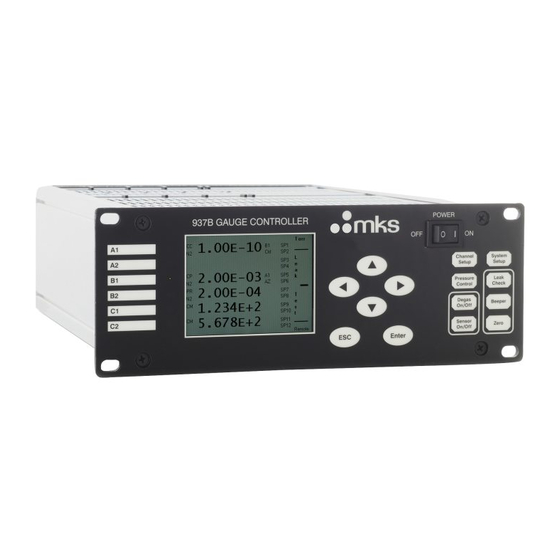
Page 16: Feature, Control Locations And Dimensions
Feature, Control Locations and Dimensions Figure 3-1 937B Front Panel Figure 3-2 937B Rear Panel Example 937B Controller Instruction Manual pg. 16... - Page 17 Channel Label LED, Indicating Active Channel Liquid Crystal Display Push Buttons for Menu Navigation Power Switch AIO Module AC Power Inlet RS232/485 Communication Port Relay Output Port Analog Output Port For optional Profibus Module Cold Cathode Module Pirani Module Capacitance Manometer Module Figure 3-3 937B External Dimensions (inches) 937B Controller Instruction Manual pg.
-
Page 18: Typical Applications For The Series 937B Controller
Typical Applications for the Series 937B Controller • Wide pressure measurement range including high vacuum and ultra-high (UHV) vacuum pressures. • Pressure measurements with multiple sensing methods (ionization, thermal conductivity, capacitance manometer). • Where a single analog output is needed over a wide range from multiple sensors. •... -
Page 19: Mks Series 937B Vacuum System Controller
Torr. A number of different MKS pressure sensors can be connected to the 937B. • MKS Baratron Capacitance Manometers with ranges from 0.02 to 10,000 Torr (up to 6) • MKS Series 423 I-Mag or Series 431/422 Cold Cathode sensors (up to 3) •... - Page 20 Controller operation is straightforward. For example, to access the system setup screen, simply push the System Setup button and many system parameters can be viewed or changed. The settings of a specific channel can be viewed or changed by first selecting the channel with the up and down keys until the green front panel LED on the desired channel is illuminated and then pushing the Channel Setup button.
-
Page 21: Operating The Series 937B Controller
Operating the Series 937B Controller 6.1 Power 937B Vacuum System Controller can be powered by universal AC voltage (100 to 240 V, 50/60 Hz). The power can be switched ON and OFF using the Power switch on the front panel. It is recommended to power OFF the controller when not in use. -
Page 22: Large Font Display
Type of sensor detected (CC = Cold Cathode, HC = Hot Cathode, PR = Pirani, CP = Convection Pirani or Convectron, CM = Capacitance Manometer or 902B Piezo,); , AR, He = Gas type; U = User Calibrated or Zeroed Pressure readings for all of the detected sensors. -
Page 23: System Setup
6.4 System Setup 6.4.1 Overview of 937B System Setup An overview of the 937B system setup parameters is shown in Figure 6-3 with the default values and the selection ranges. The system setup allows settings of parameters such as pressure unit, communication protocol, communication address, disable/enable set parameter, user calibration, define PID control and MFC ratio control recipes, and view firmware versions for the controller and modules. -
Page 24: Change And Save A Parameter Value
Figure 6-4 System Setup Information Displayed When a parameter value is indicated in red, it means the value has been changed, but not yet saved. If the setup mode is exited without performing a save, the previous unchanged parameter will be used. 6.4.3 Change and Save a Parameter Value To change and save a system setup parameter value, use the following procedure:... -
Page 25: Description Of The System Setup Parameters
The above procedure for changing a pressure unit applies equally to changing all other parameters. 6.4.4 Description of the System Setup Parameters 1. Pressure Unit This determines the units used for the pressure displayed on the front panel, the pressure queried from serial communication, and the pressure set point. - Page 26 9. PID Recipe The 937B does not have pressure control capabilities. This function is disabled in 937B as there is no MFC or pressure control valve capability. It is available in the 946 Vacuum System Controller. 10. Ratio Recipe This function is disabled in 937B as there is no MFC capability. It is available in 946 Vacuum System Controller.
- Page 27 Set DAC Parameter (P unit is torr in Eq) Equation Channel A1 V=AlogP+B 6.00E-1 7.20E+0 Channel A2 Channel B1 V=AP 1.00E+2 Channel B2 V=AlogP+B 6.00E-1 7.20E+0 Channel C1 V=AlogP+B 6.00E-1 7.20E+0 Channel C2 V=AP 1.00E+3 Combined V=AlogP+B 6.00E-1 7.20E+0 Figure 6-5 Setting DAC Logarithmic and Linear Analog Output When selecting A from the front panel, only multiples of 1, 2, and 5 are allowed.
-
Page 28: Channel Setup For Pressure Measurement
15. Display format Display format allows selection of the front panel display format. There are three options: Default, PatchZ, and HighR. Default format: only significant digits are displayed. PatchZ format: Zero(s) will be patched to enable 4-digit display for CM, and 3-digit display for CC or HC and Pirani or Convection Pirani. - Page 29 Figure 6-7 937B Channel Setup Setting Parameters, their Default Values and Ranges 937B Controller Instruction Manual pg. 29...
-
Page 30: Setup For A Capacitance Manometer
6.5.2 Setup for a Capacitance Manometer A capacitance manometer module will be automatically detected on power-up. At the same time, the connection of the capacitance manometer to the module will be checked. If no capacitance manometer is connected, - - - - will be displayed. A CM module operates up to two Capacitance Manometers, and the total combined current requirement of operating sensor(s) must be 1 amp or less. - Page 31 4. Factory Default When YES is selected and entered for Factory Default, any Manual Zero data is removed. 5. Auto Zero This selects a sensor for autozeroing of the capacitance manometer. Suitable sensors and their channels are autodetected. NA which can be selected if Auto Zero is not required. The Auto Zero will be executed only when: (1) System pressure is less than 10 (5 decades lower than the full scale)
-
Page 32: Setup For A Cp (Convection Pirani), Convectron, Or Pr Sensor
9. Enable There are three ‘ENABLE’ settings available for a relay: a. SET: forces the relay to stay in the activated (closed) state regardless of pressure and set point values b. CLEAR: forces the relay to stay in the deactivated (open) state regardless of pressure and set point values. - Page 33 dangerously, and if high enough may cause metal parts to rupture thus damaging the system and possibly injuring personnel. Read this Section for proper use of conversion data. A pressure relief valve should be installed in the system if the possibility of exceeding 1000 Torr exists.
- Page 34 4. Auto Zero Use the UP or Down arrow keys to select a valid gauge for autozeroing the Pirani (PR) or Convection Pirani (CP). Only cold or hot cathode sensors can be used as the zero reference. The zero will be executed only when: (1) The system pressure per the CC/HC is less than 1X10 Torr (1x10 Torr for the PR).
-
Page 35: Setup A Cold Cathode Sensor
10. DIR DIR determines when the relay is activated. If ABOVE is selected, the relay will be activated when the pressure is above (greater than) the set point. If BELOW is selected, the relay will be activated when the pressure is below (less than) the set point. The default setting for DIR is BELOW. - Page 36 2. User Input Calibration Gas Correction Factor (U Cal) This allows the entering of different correction factors for Cold Cathode sensors. This is useful, when the calibration gas used is not one of these listed above (N , Ar or He). The valid range is 0.1 to 50, and the default setting is 1.0.
- Page 37 5. Protect SP The Protect Set Point feature will turn OFF the Cold Cathode high voltage at the specified pressure. The Protect Set Point range for a Cold Cathode is 1.0x10 Torr to 1.0x10 Torr. The default value is 5.0x10 Torr.
-
Page 38: Setup A Hot Cathode Sensor
11. Control SP The Control Set point is used to turn the Cold Cathode sensor on or off with a higher-pressure sensor, typically a Convention Pirani, Convectron or a Capacitance Manometer (must be ≤2 Torr full scale). This prevents the cold cathode from operating at high pressure, extending the service life. - Page 39 Relative sensitivities shown in Table 6-2 may be used to determine the gas factor if the type of gas inside the vacuum chamber is known. The gas factor G is given by G = 1/R 2. Filament Indicates the filament in use. The choices are 1 or 2. Figure 6-11 Hot Cathode Setup Information Screen Symbol Relative correction factor to N...
- Page 40 Section 11.3.1. Nominal Sensitivity values are 9 Torr for the MKS Low Power Nude sensor, and 12 Torr the Mini BA sensor. These values will be automatically selected based on the type of sensor detected on power up, if no user-defined sensitivity value has been stored. Sensitivity values from 1 to 50 Torr can be entered from the front panel or over communications.
- Page 41 9. DIR To prevent the Hot Cathode from being turned ON at high pressure, the DIR for a Hot Cathode is permanently set to BELOW. Refer to Figure 8-1 and Section 8.1.2 for a more detailed description of the direction setting. 10.
-
Page 42: Power Control Of A Pressure Sensor
appropriate. However, if the protection set point is triggered, the auto control will be disabled, and the HC sensor can then only be turned ON manually. • SAFE: The filament for a Hot Cathode sensor will be automatically turned OFF by the controlling sensor, but the HC can be turned ON manually. -
Page 43: Power (Including Degas) Control Of A Sensor Via 37 Pin Aio D-Sub Connector
Up to 3 MKS low power nude or Mini BA sensors can be degassed simultaneously. The pressure must be below 1x10 Torr in order for the degas cycle to begin. If degas is attempted at a higher pressure, the Controller will display HIGH PRES for 10 seconds and will not start degas. -
Page 44: Power (Including Degas) Control Of A Sensor Using Serial Communication Commands
6.6.3 Power (including degas) Control of a Sensor using Serial Communication Commands Power to sensors can also be turned ON/OFF via serial communications. Commands for this are given in Section 9 under each gauge type. Degas of a HC sensor can also be controlled via serial commands. The commands are given in Section 9.8. - Page 45 The bar graph resolution is non-linear. The first segment displayed from the center is highly sensitive with subsequent segments decreasing in sensitivity. Disable any process control while probing the vacuum system. The set points remain active in the Leak Test function and probe entering gas may change the indicated pressure enough to switch the relay state.
-
Page 46: Installing Vacuum Sensors
7 Installing Vacuum Sensors 7.1 Over Pressure Conditions Danger of injury to personnel and damage to equipment exists on all vacuum systems that incorporate gas sources or involve processes capable of pressuring the system above the limits it can safely withstand. For example, danger of explosion in a vacuum system exists during backfilling from pressurized gas cylinders because many vacuum devices such as ionization gauge tubes, glass windows, glass belljars, etc., are not designed to be pressurized. -
Page 47: Managing Contamination In A Cold Cathode Sensor
7.2.3 Managing Contamination in a Cold Cathode Sensor Do not operate a Cold Cathode gauge at pressures above 10 Torr for extended periods. This will increase the likelihood of contamination due to higher sputtering rates. If pressure readings appear erratic, the sensor may be contaminated. In such a case, it should be visually inspected and, if contamination is visible, the internal components should be cleaned or replaced using an Internal Rebuild Kit. -
Page 48: Connecting A Hot Cathode Sensor To The Vacuum System
This hazard is not unique to this product. MKS sensors are available with either a CF type metal sealed flange, a KF type flange, or tubulation. Mount the sensor to a grounded vacuum system. KF 25 or KF 40 flanged sensors must be attached with a conductive, all-metal clamp to ensure the sensor body is grounded. -
Page 49: Installing Convection Pirani, Convectron, Or Pirani Sensors
Install the sensor with the vacuum port facing downward whenever possible. This helps to prevent particulates and liquids from entering the sensor. The use of a screen or porous filter at the port can be helpful, such as MKS seal and centering ring assembly with screen. 7.4.3... -
Page 50: Orienting The Series 345 Pirani Sensor
Use an MKS adaptive centering ring (MKS p/n 100315821) to fit a KF 16 port to a KF 10 port. In applications where the system may be subject to large voltage fluctuations, a metal centering ring with a screen should be installed. -
Page 51: Preparing The 317 Sensor For Bakeout
If excess stress is applied to the cable, use separate strain relief to prevent damage to the sensor, cable or the Controller. Cables are available from MKS in standard lengths of 10, 25, 50, and 100 feet and in custom lengths up to 500 feet. -
Page 52: Series 902B Piezo
937B/937B Baratron (CM) Baratron (CM) Function Module Connector Pin Connector Pin Connector Pin (15 pin D-sub) (9 pin D-sub) -15 V +15 V Chassis Ground Signal - Signal + +/- 15V Return Table 7-3 Pin Out of the 9 Pin D-sub Connector on CM Module. 7.6 Series 902B Piezo The Controller also supports the gas-independent Series 902B Piezo resistive gauges. -
Page 53: Connecting Relay And Analog Outputs
8 Connecting Relay and Analog Outputs Relay and analog outputs require 2.5 sec time delay to stabilize after power application. 8.1 Connecting 937B Relay Outputs There are twelve relays available in the 937B Controller which can be used to control the operation of devices associated with a vacuum system. -
Page 54: Proper Setting Of A Relay
8.1.2 Proper Setting of a Relay Several parameters need to be correctly set to properly use the relays in a 937B Controller. Figure 8-1 shows that manner in which these parameters are defined. ABOVE BELOW Setpoint Hysteresis Hysteresis Setpoint Relay Relay Relay Relay... -
Page 55: Relay Inductive Loads And Arc Suppression
When direction is set to ABOVE, the hysteresis must be lower than the set point, while when the direction is set to BELOW, the hysteresis must be higher than the set point. When Direction is changed, hysteresis is set to a default value (of about 10%). Depending on the application, this value may need to be optimized. -
Page 56: Buffered Analog Output
Description Description Buffered Aout A1 Log/Lin Aout C1 Buffered Aout A2 Log/Lin Aout C2 Buffered Aout B1 Combination Aout 1 Buffered Aout B2 Combination Aout 2 Buffered Aout C1 Power A1 Buffered Aout C2 Power A2/Degas A1 Log/Lin Aout A1 Power B1 Log/Lin Aout A2 Power B2/Degas B1... - Page 57 Figure 8-3 Buffered Analog Output for Cold Cathode Sensors (431/422/423) in N 937B Controller Instruction Manual pg. 57...
- Page 58 Pressure, Torr Buffered Vout, V Pressure, Torr Buffered Vout, V 1.0E-11 0.0000 4.0E-07 6.8993 1.5E-11 0.3286 6.0E-07 7.0871 2.0E-11 0.5634 8.0E-07 7.2222 3.0E-11 0.8994 1.0E-06 7.3247 4.0E-11 1.1416 1.5E-06 7.5140 6.0E-11 1.4585 2.0E-06 7.6551 8.0E-11 1.7035 3.0E-06 7.8469 1.0E-10 1.8882 4.0E-06 7.9769 1.5E-10...
- Page 59 Figure 8-4 Buffered Analog Output for Hot Cathode Sensors 937B Controller Instruction Manual pg. 59...
- Page 60 Figure 8-5 Buffered Analog Output for a 345 Pirani Sensor 937B Controller Instruction Manual pg. 60...
- Page 61 Pressure, Torr Buffered N Vout, V Buffered Ar Vout, V Buffered He Vout, V 1.0E-04 0.6323 0.6324 0.6340 1.5E-04 0.6347 0.6339 0.6362 2.0E-04 0.6372 0.6355 0.6384 3.0E-04 0.6420 0.6385 0.6426 4.0E-04 0.6468 0.6414 0.6469 6.0E-04 0.6563 0.6474 0.6553 8.0E-04 0.6656 0.6533 0.6636 1.0E-03...
- Page 62 Range Equation Nitrogen 0.63<V<9.3 V <p <20 Torr 3935 9.3 V< V <9.72 V 20 <p< 1 Torr Argon 0.63<V<7.79 V <p<20 Torr 7.79 V<...
- Page 63 Figure 8-6 Buffered Analog Output for the 317 Convection Pirani Sensor or 275 Convectron Sensor 937B Controller Instruction Manual pg. 63...
- Page 64 Pressure, Torr Buffered N Vout, V Buffered Ar Vout, V Buffered He Vout, V 1.0E-04 0.5639 0.5674 0.5654 1.5E-04 0.5650 0.5680 0.5663 2.0E-04 0.5660 0.5687 0.5671 3.0E-04 0.5681 0.5699 0.5688 4.0E-04 0.5702 0.5712 0.5705 6.0E-04 0.5744 0.5737 0.5738 8.0E-04 0.5785 0.5762 0.5771 1.0E-03...
- Page 65 Range Equation Nitrogen 0.56<V<8.3 V <p <40 Torr 3156 8.3 V< V <8.8 V ...
- Page 66 Buffered Capacitance Manometer Analog Output Full Scale Range (Torr) 1000 10,000 0.01 Pressure, Torr Figure 8-7 Buffered Analog Output for Capacitance Manometers 937B Controller Instruction Manual pg. 66...
-
Page 67: Logarithmic/Linear And Combination Analog Output
Logarithmic/Linear and Combination Analog Output Since most of the buffered analog outputs are non-linear, logarithmically linearized or linear analog outputs are also provided for each individual sensor. However, since the logarithmic/linear analog outputs are processed by the microprocessor, these are updated only every 50 msec, regardless of the number of sensors being connected to the controller. - Page 68 Set Combination Channel Parameter High Middle Enable Combo #1 Enable Combo #2 Disable Figure 8-8 Setup Screen for Setting Combination Channel Parameters Once the combination sensors are selected, enable the combined analog output. If invalid channels are selected, the Enable indicator will stay in the Disabled mode. The following rules may be used to simplify the combination configuration.
-
Page 69: Logarithmic/Linear Analog Output When The Sensor Power Is Turned Off
• Set the sensor combination @254SPC1!HH,MM,LL;FF and @254SPC2!HH,MM,LL;FF . Here, HH, MM and LL are the channels (A1, A2, B1, B2, C1, C2, NA) corresponding to the sensor assigned to High, Middle, and Low range segments. • Query the gauge combination @254SPC1?;FF and @254SPC2?;FF . -
Page 70: Rs232/485 Serial Communication Commands
9 RS232/485 Serial Communication Commands 9.1 Serial Communication Wiring Diagram Description RS485(-)/RS232TxD/(B) RS485(+)/RS232RxD/(A) Ground Table 9-1 937B Serial Communication Wiring Diagram 9.2 Communication Protocols Cable length with RS232 signals 50 ft (15 m) Cable length with RS485 signals 4000 ft (1200 m) Baud rate 9600, 19200, 38400, 57600, 115200 Character format... -
Page 71: Pressure Reading Commands
9.3 Pressure Reading Commands Command Function Response Meaning Single Channels Read pressure Pressure in selected units for PR, CP, CC & HC d.d0Eee (n=1 to 6) on Channel n (d,e=0 to 9) Pressure in selected units for CM d.dddEe (d,e =0 to 9) CM, when CM output is negative. -
Page 72: Relay And Control Setting Commands
9.4 Relay and Control Setting Commands Command Parameter Response Function Query or set a set point for relay m, response with the d.dd Eee d.dd Eee (m=1 to 12) current setting value. (d,e=0 to 9) (d,e=0 to 9) If 0 is used as the parameter, the set point will be set as its low limit value. -
Page 73: Capacitance Manometer Control Commands
9.5 Capacitance Manometer Control Commands Command Parameter Response Function RNGn Query or set the full-scale pressure measurement range d.dd Eee d.dd Eee (n=1 to 6) for a capacitance manometer. Valid range is from 0.01 to 10000, and default range is 1000 Torr. CMTn ABS or ABS or... -
Page 74: Cold Cathode Control Commands
9.7 Cold Cathode Control Commands Command Parameter Response Function PROn Query or set protection set point value for sensor on channel d.dd Eee d.dd Eee (n=1, 3, 5) n. The valid PRO range is 1x10 to 1x10 Torr. Use 0.0 to (d,e=0 to 9) (d,e=0 to 9) disable the protect set point control. -
Page 75: Hot Cathode Control Commands
9.8 Hot Cathode Control Commands Command Parameter Response Function PROn Query or set protection set point value for sensor on channel d.dd Eee d.dd Eee (n=1, 3, 5) n. The valid PRO range is 1x10 to 1x10 Torr. Use 0.0 to (d,e=0 to 9) (d,e=0 to 9) disable the protect set point control. -
Page 76: System Commands
9.9 System Commands Command Parameter Response Function Query or set controller address (1 to 253) (aaa=001 to (aaa=001 to 254 is reserved for broadcasting. Default = 253. 253) 253) Query or set baud rate (valid # = 9600, 19200, 38400, 57600, 115200), default = 9600. - Page 77 DLTn LIN or LOG LIN or LOG Query or set the type of DAC linear (LIN, V=A*P) of (n=1 to 6) logarithmic linear (LOG, V=A*LogP+B) output. Default setting is LOG. (Only LOG is allowed for combined output) DLAn Query or set the DAC slope parameter A. Default value d.dd Eee d.dd Eee (n=0 to 6)
-
Page 78: Error Codes
9.10 Error Codes When serial commands are used in communicating with 937B, an error code will be returned if an invalid command or an invalid parameter is sent. The error code can be displayed in either in TXT or CODE mode, and can be selected by using @254SEM!TXT;FF or @254SEM!CODE;FF command, respectively. -
Page 79: Profibus Communication Protocol And Commands
9.11 937B ProfiBus communication protocol and commands 9.11.1 Electrical Connections Pin Number Description RxD/TxD+ RxD/TxD- V+ (+5Vdc) Ground Table 9-11 937B PROFIBUS electrical connections. The address for PROFIBUS ranges from 00 to 99 (decimal) and can be selected from two switches on the rear panel of the optional 937B PROFIBUS module. - Page 80 Ctrl Set point Ch B2 CSP4 Ctrl Set point Ch C1 CSP5 Ctrl Set point Ch C2 CSP6 Ctrl Enable Ch A1 CTL1 Off/Safe/Auto/ Local Setting Ctrl Enable Ch A2 CTL2 Ctrl Enable Ch B1 CTL3 Ctrl Enable Ch B2 CTL4 Ctrl Enable Ch C1 CTL5...
-
Page 81: Profibus Output Buffer Map
9.11.3 937B PROFIBUS output buffer map NOTE: Commands relating to MFCs or flow are not available on the 937B Controller. OUTPUT Buffer Map Offset Size Format Description Bit field Bit 0 Enable / Clear Set point Relay 1 Bit 1 Enable / Clear Set point Relay 2 Bit 2 Enable / Clear Set point Relay 3 Bit 3 Enable / Clear Set point Relay 4 Bit 4 Enable / Clear Set point Relay 5... - Page 82 Bit field Bit 0 Active Filament Select HC Channel A1 Bit 1 Active Filament Select HC Channel A2 Bit 2 Active Filament Select HC Channel B1 Bit 3 Active Filament Select HC Channel B2 Bit 4 Active Filament Select HC Channel C1 Bit 5 Active Filament Select HC Channel C2 Bit 6...
- Page 83 9.11.4 937B PROFIBUS input buffer map INPUT Buffer Map Offset Size Format Description Float Pressure Channel 1 Float Pressure Channel 2 Float Pressure Channel 3 Float Pressure Channel 4 Float Pressure Channel 5 Float Pressure Channel 6 Byte Status for Channel 1 NOGAUGE NEGATIVE CONTROL...
- Page 84 PROTECT WAIT RP_OFF Degas FAULT OPEN (for MFC only) CLOSE( for MFC only) SET POINT( for MFC only) PID( for MFC only) Byte Status for Channel 4 NOGAUGE NEGATIVE CONTROL PROTECT WAIT RP_OFF Degas FAULT OPEN (for MFC only) CLOSE( for MFC only) SET POINT( for MFC only) PID( for MFC only) Byte...
- Page 85 NEGATIVE CONTROL PROTECT WAIT RP_OFF Degas FAULT OPEN (for MFC only) CLOSE( for MFC only) SET POINT( for MFC only) PID( for MFC only) Bit Field Bit 0 Set point Relay State Relay 1 Set point Relay State Relay 2 Set point Relay State Relay 3 Set point Relay State Relay 4 Set point Relay State Relay 5...
-
Page 86: Maintenance Of Series 937B Controller Modules
10 Maintenance of Series 937B Controller Modules Lethal voltages are present in the controller when it is powered. Disconnect the power cable before disassembly. Do not connect or disconnect any electrical connectors while power is applied to the equipment (hot swapping). Doing so may cause damage to the equipment or severe electrical shock to personnel. -
Page 87: Removing And Installing Aio Module
10.2 Removing and Installing AIO Module The power cord receptor, the RS232/485 communication 9-pin D-Sub connector, the 25 pin D-Sub Relay output connector, and the 37-pin D-Sub Analog output connectors are located on the back panel of the AIO (Analog Input/Output) module. To remove the AIO module: Lethal voltages are present in the controller when it is powered. -
Page 88: Removing And Installing Profibus Control Module
To install the AIO module: 1. Assure that the controller power is OFF and the power cord is disconnected. 2. Align the module to fit and slide freely in the card guides, with the internal 48-pin DIN connector end first. 3. -
Page 89: Mounting The Controller
Optional mounting hardware is available for mounting the 937B Controller in a 19-inch rack. • Mounting a single 937B Controller into a 19" rack using MKS half-rack mounting kit part number 100005651: 1. Attach the faceplate (3.5"x5.5") to each side of the 937B front panel using the four 10-32 screws provided. -
Page 90: Ac Power Cord
All items in the kit may not be needed, depending on the mounting configuration. Contact an MKS Applications Engineer for solutions to other mounting configurations. 10.5 AC Power Cord The Controller has a standard female IEC 60320 connector for connecting to a 100-240 VAC, 50/60 Hz power source. -
Page 91: Maintenance And Service Of Mks Vacuum Sensors
Ambient gas molecules are ionized by a high voltage discharge in Cold Cathode sensors and sensitivity is enhanced by the presence of a magnetic field. MKS Cold Cathode sensors utilize an inverted magnetron design that includes an isolated collector, as shown in Figure 11-1. This makes the sensor less susceptible to contamination and allows a wider range of pressure measurement. -
Page 92: Maintenance Of Series 431/422 Cold Cathode Sensor
The cathode is isolated from the grounded metal housing. The inverted magnetron geometry produces more stable signal output, and also works well to low pressure without risk of extinguishing the discharge. The range of the MKS Instrument’s cold cathode sensors is extended to 10 Torr by using a large series resistor to decrease sputtering within the sensor. - Page 93 Figure 11-3 Exploded View of the 431/422 Cold Cathode Gauge Assembly 5. Remove the six 1/4-28 x 0.875" socket head cap screws (10) and pull the back flange (13) free. Note that these screws are silver-plated for lubricity and should be used only once. They may be re-lubricated with a dry lubricant such as molybdenum disulfide, though new silver- plated screws are recommended.
-
Page 94: Cleaning The Series 431/422 Sensor
The cathode and anode assemblies are attached to the flange. Disassembl y should proceed from the bot tom to the top of the internal assembl y draw ing . 6. To remove the cathode (23), release the two integral, spring-loaded ears that are hooked over the shoulder of the ceramic insulating support (19). -
Page 95: Preparing The Sensor For Bakeout
11.2.5 Testing a Cold Cathode Sensor MKS cold cathode sensors contain anode and cathode (collector) electrodes. Test the sensor with an ohmmeter. There should be no shorts between the electrodes or from the electrodes to the sensor body. - Page 96 Flathead Screw (2) Magnet Ion Current High Voltage Feedthrough Pin Feedthrough Pin Glass Insulator Leaf Spring Locating Collar Anode Sensor Body Ground Shield Ceramic Spacer, Small Cathode Grid Washer Ceramic Spacer, Large Compression Spring Figure 11-4 Exploded View of the Series 423 I-Mag Cold Cathode Gauge Sensor Do not bend the anode (10) or the leaf spring (1) on the ion current feed-through pin when assembling or disassembling the sensor.
-
Page 97: Clean The I-Mag Sensor
11.3.2 Clean the I-Mag Sensor Depending on the degree of contamination and the application of the sensor, the internal parts may be cleaned — either ultrasonically, with mild abrasives, or chemically. Do not touch any vacuum-exposed part after cleaning unless wearing gloves. Ultrasonically clean surfaces using only high-quality detergents compatible with aluminum (i.e. -
Page 98: Preparing The Sensor For Bakeout
7. Using your thumbs, push the larger end of the spring into the sensor body (9) until it is contained within the tube's inside diameter. 8. Using the smooth-jaw, needle-nose pliers, work the compression spring (3) down into the sensor body (9) until it is fully seated in the formed groove. -
Page 99: Cleaning The Hot Cathode Sensor
Figure 11-5 Bayard Alpert Gauge Structure and Electron Processes The collection ion current is related to the pressure and emission current by the equation where, is the sensitivity factor which depends strongly upon the electron accelerating structure and operating condition. Typical sensitivity factor for nitrogen is around 7.5 to 15 Torr To reduce the outgassing within the hot cathode to a negligible level and minimize the effect of ESD (electron stimulated desorption) on high vacuum measurement, high temperature degassing techniques are used to drive off any adsorbed gas molecules from the surface of the anode grid. -
Page 100: Maintenance Of A Pirani Sensor
F1 and F2 are identified on the Low Power Nude sensor (HC). For a Mini BA, use the drawing in Figure 11-6 to locate F1 and F2. Figure 11-6 Filament Pin Locator for LPN and Mini BA Hot Cathodes 11.5 Maintenance of a Pirani Sensor Theory of a Pirani Pressure Sensor Measurement of pressure with any type Pirani sensor is based on the thermal conductivity of the gas type and amount in the vacuum environment. -
Page 101: Cleaning The Series 345 Sensor
Figure 11-8 Natural Convection Heater Transfer in Horizontal (left) and Vertical (right) Sensor Tubes. The size of gas molecules has significant impact on the Pirani sensor. Since smaller molecules (such as helium) move faster in the gas, this gas can transfer more heat energy under the same pressure as compared with a gas composed of heavy molecules (e.g. -
Page 102: Cleaning The Series 317 Sensor
345 D-sub Pin # Resistance (Ω) 4 to 7 4 to 8 6 to 7 6 to 8 5 to 6 3 to 5 Table 11-2 Bridge Resistance Value for a Normal 345 Pirani Sensor 11.5.3 Cleaning the Series 317 Sensor Roughing pump oils and other fluids condensing or decomposing on the heated filament can contaminate the sensor. -
Page 103: Maintenance Of A Capacitance Manometer
Theory of a Capacitance Manometer The MKS Capacitance Manometer head contains a sensor and signal conditioner. The sensor is made up of a tensioned metal diaphragm, one side of which is exposed to the media whose pressure is to be measured. -
Page 104: Spare Parts And Accessories
12 Spare Parts and Accessories Part # Accessories USA power cable 103150001 Half rack mounting kit 100005651 Full rack mounting kit 100007700 937B Instruction Manual 100016467 Rebuild kit for Series 431 or 422 100006734 Spanner Wrench for 431 or 422 tube rebuild 100005279 Rebuild kit for Series 423 I-Mag 100002353... - Page 105 Cable for 275 Convectron Sensor 10 ft (3.0 m) 100016890 25 ft (7.6 m) 100016891 50 ft (15.2 m) 100016892 Contact the MKS Customer Service Department to order any of these parts or for technical support. 937B Controller Instruction Manual pg. 105...
- Page 106 Series 937B Vacuum System Controller Operation and Maintenance Manual Instruction Manual p/n: 100016467 Rev F, August 2020 937B Controller Instruction Manual pg. 106...
Need help?
Do you have a question about the 937B Series and is the answer not in the manual?
Questions and answers