MKS 937B Series Manuals
Manuals and User Guides for MKS 937B Series. We have 3 MKS 937B Series manuals available for free PDF download: Operation And Maintenance Manual

MKS 937B Series Operation And Maintenance Manual (131 pages)
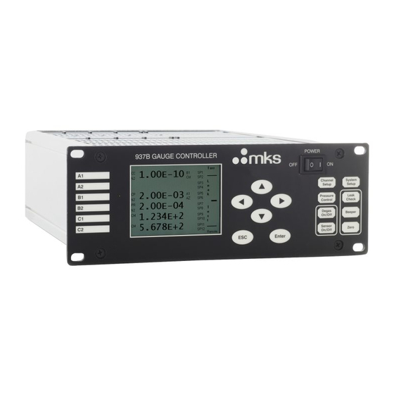
High Vacuum Multi-Sensor System
Brand: MKS
|
Category: Controller
|
Size: 1 MB
Table of Contents
-
-
Controller10
-
Sensors12
-
-
-
Power23
-
System Setup25
-
-
-
-
-
-
System Commands101
-
-
Power Supply105
-
AC Power Cord107
-
-
14 Appendix
126
Advertisement

MKS 937B Series Operation And Maintenance Manual (120 pages)
High Vacuum Multi-Sensor System
Brand: MKS
|
Category: Controller
|
Size: 4 MB
Table of Contents
-
Controller10
-
Sensors12
-
Power22
-
System Setup24
-
Error Code80
-
Power Supply97
-
Appendix117
-
Product Warranty120
MKS 937B Series Operation And Maintenance Manual (106 pages)
Vacuum System Controller
Brand: MKS
|
Category: Controller
|
Size: 3 MB
Table of Contents
-
Power21
-
System Setup23
-
Error Codes78
Advertisement
Advertisement