MKS 937B Series Operation And Maintenance Manual
High vacuum multi-sensor system
Hide thumbs
Also See for 937B Series:
- Operation and maintenance manual (131 pages) ,
- Operation and maintenance manual (106 pages)

Related Manuals for MKS 937B Series


Summary of Contents for MKS 937B Series
- Page 1 S Se eries s 93 High Vacu ti-Sen nsor S Syste Opera ation a and M Mainte enanc ce Ma anual Part #: 1 100016467 RevC...
-
Page 2: Table Of Contents
Locating a Cold Cathode Sensor ................48 7.1.2 Orienting a Cold Cathode Sensor ................48 7.1.3 Managing Contamination in a Cold Cathode Sensor ..........48 7.1.4 Connecting the Series 421/422 Sensor ..............48 7.1.5 Connecting the 423 I-MAG Sensor ................49 MKS 937B Operation Manual... - Page 3 Orienting the Series 345 Pirani Sensor..............52 7.3.5 Connecting the Series 317/345 Sensors ..............52 7.3.6 Preparing the 317 Sensor for Bakeout............... 54 Capacitance Manometers - MKS Baratron ..............54 7.4.1 Installing a Baratron Capacitance Manometer ............54 7.4.2 Connecting a Baratron™ Capacitance Manometer ........... 54 Connecting Relay and Analog Outputs ...................
- Page 4 Theory of a capacitance manometer ............... 112 12.5.2 Repairing the Baratron™ Capacitance Manometer ..........113 Spare Parts and Accessories ....................114 APPENDIX ..........................117 14.1 Hot cathode gauge gas correction factors ..............117 Product Warranty ........................120 MKS 937B Operation Manual...
- Page 5 Schematic of a Pirani thermal conductivity sensor............. 110 Figure 12-8 Natural convection heater transfer in horizontal (left) and vertical (right) sensor tubes..110 Figure 12-9 Exploded view of a MKS Capacitance manometer sensor..........112 MKS 937B Operation Manual...
- Page 6 Resistance readings of a normal HC sensor............... 109 Table 12-2 Bridge resistance value for a normal 345 Pirani sensor............111 Table 12-3 Resistance values for a normal 317 convection enhanced Pirani sensor......112 MKS 937B Operation Manual...
-
Page 7: Package Contents
Inspect the 937B system for visible evidence of damage. If it has been damaged in shipping, notify the carrier immediately. Keep all shipping materials and packaging for ® claim verification. Do not return the product to HPS Products. MKS 937B Operation Manual... -
Page 8: Safety Information
Do not substitute parts or modify the instrument. Do not install substitute parts or perform any unauthorized modification to the instrument. Return the instrument to an MKS Calibration and Service Center for service and repair to ensure that all safety features are maintained. - Page 9 Only use a detachable cord set with conductors having a cross-sectional area equal to or greater than 0.75 mm . The power cable should be approved by a qualified agency such as VDE, Semko, or SEV. MKS 937B Operation Manual...
-
Page 10: Specifications
Design and/or specifications are subject to change without notice. The measurement range depends upon the sensor options selected. Relay setpoint values are automatically adjusted when pressure unit is changed. The protection setpoint is always enabled in 937B. MKS 937B Operation Manual... - Page 11 9½" x 12¼" x 3½" (241 mm x 311 mm x 88 mm) Size ½ rack, 2U high Typical weight 8.0 lb (3.6 kg) CE certification EMC Directive: 2004/108/EEC Low Voltage Directive: 73/23/EEC Logarithmic/linear and combined logarithmic analog outputs can be customized using the system setup manual. MKS 937B Operation Manual...
-
Page 12: Sensors
(Miniature Ionization Gauge, or LPN (Low Power Nude), glass enveloped gauges and UHV nude type. Pirani Series 345 Pirani CP (Convection Pirani) Series 317 Convection Pirani (CM) Capacitance Manometer MKS unheated Baratron (622A, 623A, 626A, 722A ); ® MKS 45 C heated Baratron (624B,D24B, 627B,D27B); ®... - Page 13 Series 421and 422 - 1.8 in (30 cm Series 423 - 0.9 in (15 cm Trailing zeros displayed on LCD screen do not reflect the resolution of the pressure reading. Volume will vary with the type of vacuum connection selected MKS 937B Operation Manual...
- Page 14 Hot Cathode filament type LPN & Mini BA Tungsten (W) or Yittria (Y ) coated iridium Glass BA Tungsten (W), Yittria (Y ) coated iridium or Thoria (ThO) coated iridium Hot Cathode degas power (E-beam, at grid) MKS 937B Operation Manual...
- Page 15 2-3/4” CF (non-rotatable) KF16, 8 VCR -F (1/2”), 8 VCO -F (1/2”),1-1/3” CF (non- ® ® rotatable), ½” tube The hot cathode X-ray limit can be corrected by using a serial command. See section 9.6 for details. MKS 937B Operation Manual...
-
Page 16: Controller Display Messages
The CC/HC is controlled by another gauge (PR/CP) PR/CP/BR may be auto-zeroed by its control gauge F1, F2 Active filament The HC is degassing An, Bn, Cn The channel where the control gauge is installed (n=1, 2) MKS 937B Operation Manual... -
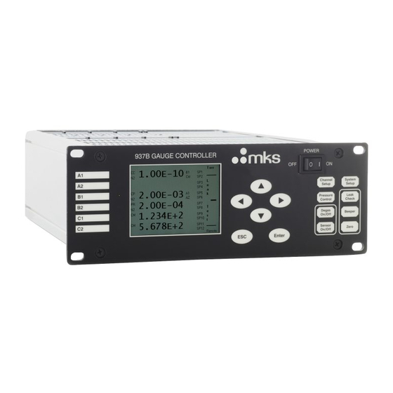
Page 17: Feature, Control Locations And Dimensions
3 Feature, Control Locations and Dimensions Figure 3-1 937B front Panel. Figure 3-2 937B rear panel. MKS 937B Operation Manual... -
Page 18: Figure 3-3 937B External Dimensions (Inches)
Contro ol Module old Cathode M Module gh Voltage BN NC connector urrent BNC co onnector rani Module apacitance ma anometer Mo dule Figure 3-3 937B ex xternal dimen nsions (inche es). MKS 937B B Operation Ma anual... -
Page 19: Typical Applications For The Series 937B Controller
Controlling system pressure by using the analog output as the input to an automatic pressure controller. Starting or stopping system processes using relay set points. Measuring backfill pressures. Leak testing vacuum systems. Controlling acceleration and light source vacuum systems. MKS 937B Operation Manual... -
Page 20: Hps Products Series 937B Multi-Sensor High Vacuum System
RODUCTS ERIES pressure measuremen t between 1 torr to 2 2 10 torr. A number of dif fferent MKS p pressure sens sors, listed belo ow can be con nnected to the e 937B: MKS Baratron Capacitance Manometers s with heads f from 0.02 to 2... - Page 21 (for both cold cathode or hot cathode). Direct computer communication is available to control front panel functions or read pressure and other information remotely. A RS232/485 serial port is available and the communication protocol can be selected from the System Setup panel. MKS 937B Operation Manual...
-
Page 22: Operating The Series 937B Controller
The standard front panel display for the 937B is shown in Figure 6-1: 1.00E-10 Torr Ctrl ----- 1.00E-10 Ctrl 1.20E-03 SP10 3.505E-2 SP11 SP12 Remote Figure 6-1 Standard 937B LCD front panel display for pressure measurement under Leak detection mode. MKS 937B Operation Manual... -
Page 23: Large Font Displays
When the large font display is selected, one channel is displayed as large font (B1 as shown in the figure) and the pressure readings for all the detected sensors are displayed in smaller font of the left side of the LCD. MKS 937B Operation Manual... -
Page 24: System Setup
In addition, the logarithmic/linear analog output for individual channel and combined logarithmic/linear analog output can be adjusted by setting the DAC parameters. Figure 6-3 937B system setup parameters, their default values and ranges. MKS 937B Operation Manual... -
Page 25: Display System Setup Parameters
Enter 5. To save an updated value, press the key while the background of the parameter value is Pascal Enter black (i.e. in this example). After is pressed, the background of the selected MKS 937B Operation Manual... -
Page 26: Description Of The System Setup Parameters
However, these values can still be viewed from the display, or queried using serial communication: Gas Type User Calibration AO delay Protect setpoint Relay direction, setpoint and hysteresis Control setpoint Channel, setpoint and hysteresis Gas Type MKS 937B Operation Manual... - Page 27 13. DAC Parameter Setup The Log/Linear analog output for each individual channel, as well as the combination analog output can be accessed by adjusting the DAC parameter. To view or modify the DAC parameter, MKS 937B Operation Manual...
-
Page 28: Figure 6-5 Setting Dac Logarithmic And Linear Analog Output
1000 torr Baratron. However, if 1E+2 is selected, the 10V full scale analog output will occur at 1x10 torr, and this might be a good choice for a Pirani if you are interested in its 1x10 to 1x10 torr measurement range. MKS 937B Operation Manual... -
Page 29: Figure 6-6 System Firmware And Serial Number Information Displayed On 937B Lcd Screen
The system firmware information for all of the modules installed in the 937B is displayed when ON is selected. The serial numbers for all detected boards are also displayed, as shown in Figure 6-5. Figure 6-6 System firmware and serial number information displayed on 937B LCD screen. MKS 937B Operation Manual... -
Page 30: Channel Setup For Pressure Measurement
Figure. The type of sensor is automatically Channel detected when the key is pressed and the corresponding interface will be displayed; no manual Setup selection is required. MKS 937B Operation Manual... - Page 31 Figure 6-7 937B Channel Setup setting parameters, their default values and ranges. MKS 937B Operation Manual...
-
Page 32: Setup For A Capacitance Manometer
0 V), and U represents uni-directional (for example, 10U means 0 to 10 V input voltage, and voltage at zero differential pressure is 5 V, exactly at the middle of the input range). 3. Range MKS 937B Operation Manual... - Page 33 When a capacitance manometer has been manually zeroed, a U will be displayed under the gauge type indicator (CM) to indicate that this manometer is user calibrated. 7. Relay Relays for each capacitance manometer channel are preset (2 per channel), as shown below. These values are auto-detected. MKS 937B Operation Manual...
-
Page 34: Setup For A Pr (Pirani)/Cp (Convection Pirani) Sensor
However, when a dummy sensor is connected to the controller, it cannot detect the sensor automatically. Under this condition, the sensor type can be selected manually, and stored in the memory. This information will be used as the default sensor type if sensor power is cycled. 2. Gas Type MKS 937B Operation Manual... - Page 35 1x10 torr. The default setting for the Auto Zero function is NO. Ensure that the Pirani/CP and the reference auto-zero ion gauge sensor are connected to the same chamber at all times. 5. Manual Zero MKS 937B Operation Manual...
- Page 36 When the setpoint value has been changed, the hysteresis value will be changed automatically. If DIR is set to ABOVE, the hysteresis will automatically be set to 0.5xSetpoint; if DIR is set to BELOW, the hysteresis is automatically set to 1.5xSetpoint. MKS 937B Operation Manual...
-
Page 37: Setup A Cold Cathode Sensor
Fast Relay SP described here. The hysteresis is approximately 15% of the setpoint value, that is, the relay will be re-energized when the system pressure is 15% below the setpoint. The default setpoint value is 1x10 torr. MKS 937B Operation Manual... - Page 38 SET: forces the relay to stay in the activated state (closed) regardless of pressure and setpoint values CLEAR: forces the relay to stay in the deactivated state (open) regardless of pressure and setpoint values. ENABLE: the relay status is determined by the pressure, setpoint value, and direction. MKS 937B Operation Manual...
- Page 39 Control SP function can be enabled. There are three choices: AUTO: the high voltage for a cold cathode gauge is controlled solely and automatically by the controlling gauge (PR/CP). However, if the protection setpoint is MKS 937B Operation Manual...
-
Page 40: Setup A Hot Cathode Sensor
Protect Setpoint 5.0E-03 Relay Enable Dir/Ch SET SP Hyst Relay 01 BELOW 1.0E-06 9.0E-07 Relay 02 CLEAR BELOW 3.0E-05 3.3E-05 Relay 03 ENABLE BELOW 2.0E-08 1.8E-09 Relay 04 CLEAR BELOW 5.0E-07 5.5E-07 Control SP SAFE 1.0E-03 1.2E-03 MKS 937B Operation Manual... -
Page 41: Figure 6-11 Hot Cathode Setup Information Displayed On 937B Lcd Screen
1 minute. The default value is 30 min. 4. Sensitivity Indicates sensitivity of the hot cathode gauge. Its typical value is 9 Torr for the MKS Low Power Nude sensor, and 12 Torr for the Mini BA gauges. These default values will be automatically selected based on the type of sensor being detected if no user-defined sensitivity value is stored. - Page 42 5x10 torr. If the controlling gauge (PR/CP/CM) and hot cathode gauge are connected to the same chamber, make sure the control SP is less than 5x10 torr, otherwise the HC sensor MKS 937B Operation Manual...
-
Page 43: Power Control Of A Pressure Sensor
(PR/CP). If it is in the AUTO control mode, disable the control On/off setpoint before using the front panel keypad to operate the ion gauge. Sensor 3. The key switches the corresponding sensor on and off. On/off MKS 937B Operation Manual... -
Page 44: Power (Including Degas) Control Of A Sensor Via 37 Pin Aio Dsub Connector
When MKS low power nude or Mini BA gauges are used, these sensors (up to 3) can be degassed simultaneously. However, if glass BA is used, only one glass BA sensor can be degassed at a time because of its extremely high degas power consumption (close to 50 W at grid). -
Page 45: Power (Including Degas) Control Of A Sensor Using Serial Communication Commands.45
6.7.1 Leak test principle applied for the 937B A leak test with the Series 937B Controller is not intended to replace mass spectrometer leak detectors. It offers a simple and inexpensive method for locating leaks in high vacuum systems. Under ideal MKS 937B Operation Manual... -
Page 46: Procedures For A Leak Test With The 937B
As with any leak testing, many factors can influence the sensitivity of the test. Described in greater detail below, these include the chamber volume; system pressure; probe gas; type of vacuum pump; location of the Sensor, leak, and pump; and others such as pumping speed and system tube size. MKS 937B Operation Manual... - Page 47 1. With the Controller on, pump down the system to a base pressure. 2. Close a valve to isolate the pump. 3. Measure the rise of the pressure over a time interval. A very fast rise indicates a leak. 4. Repeat this procedure as often as necessary. MKS 937B Operation Manual...
-
Page 48: Installing Vacuum Sensors
C Custom cable es can be fab bricated for the ese situations Use SHV and BNC con nnectors for a all application MKS 937B B Operation Ma anual... -
Page 49: Connecting The 423 I-Mag Sensor
The HPS nipple includ des a screen that helps to prevent ion c coupling. This s mounting is also recomme nded to assu re the nomina al rated sensi tivity of the ga auge. MKS 937B B Operation Ma anual... -
Page 50: Connecting A Hot Cathode Sensor To The 937B Controller
Since much high power is required to operate hot cathode gauge, especially, during degas process, the maximum allowed cable length of a hot cathode is restricted to less than 50 ft (15 m), which is significantly shorter than that is allowed for operating a cold cathode sensor. MKS 937B Operation Manual... -
Page 51: Figure 7-2 Lpn Gauge Cable Diagram
Hot cat hode cables have severa al special ch aracteristics s, including l ethal voltage ® herefore only y cables sup plied by HPS Products should be u sed. MKS 937B B Operation Ma anual... -
Page 52: Installing Pirani Sensors
Do not use a compression mount (quick connect) to attach the Sensor to a system in positive pressure applications. A solid electrical connection between the Sensor and the grounded vacuum system must be provided to shield the tube element from external radiation sources. MKS 937B Operation Manual... -
Page 53: Figure 7-4 317/345 Cable Diagram
Descript tion Bridge d drive + Bridge d drive - Chassis s ground Signal + Signal - Bridge s sensor leg Bridge r reference leg ble 7-3 out for 317/3 345 cables. MKS 937B B Operation Ma anual... -
Page 54: Preparing The 317 Sensor For Bakeout
MKS unhe eated Baratrons (622A, 623A A, 626A, 722 A ), and MKS S 45 C heated d Baratrons (624B,D24B, 627B,D27B). ® ® ® Capacitan nce manomet... -
Page 55: Figure 7-5 The Wiring Diagram For The Capacitance Manometer Cable
9 937B controll er. Detailed w wiring for the cable is s hown in Figur re 7-5. Figure The wi ring diagram m for the Cap pacitance Ma anometer cab ble. MKS 937B B Operation Ma anual... -
Page 56: Connecting Relay And Analog Outputs
Relay 10 Common Relay 5 NO Relay 11 NO Relay 5 Common Relay 11 Common Relay 6 NO Relay 12 NO Relay 6 Common Relay 12 Common No Connection Table 8-1 Pin out for the 937B relay output. MKS 937B Operation Manual... -
Page 57: Proper Setting Of A Relay
For example, when a main high vacuum isolation valve is opened, a small pressure rise may occur in the vacuum system. If the hysteresis is close to or identical with the pressure setpoint, MKS 937B Operation Manual... -
Page 58: Relay Inductive Loads And Arc Suppression
Bu ffered and log garithmic ana alog outputs ar re simultaneo ously available e from all sen nsors. The de tailed assignm ment for thes e pins is described d in Table 8-2 MKS 937B B Operation Ma anual... -
Page 59: Buffered Analog Output
To avoid problems, logarithmic analog output is used as the buffered analog output. Buffered analog output for the cold cathode, hot cathode, Pirani, convection Pirani and capacitance manometers are shown in following figures and tables. MKS 937B Operation Manual... -
Page 60: Figure 8-3 Buffered Analog Output For Cold Cathode Gauges (421/422/423) In N
Buffered Cold Cathode Analog Output (N (Series 421 and 423) Pressure, Torr Figure 8-3 Buffered analog output for cold cathode gauges (421/422/423) in N MKS 937B Operation Manual... -
Page 61: Table 8-4 Buffered Analog Output For The Cold Cathode Gauges (421/422/423) In N
Table 8-5. Range Equation V<2.2V exp( 3546 3941 9901 4259 2.2 V< V <3.71 V 7722 1969 V>3.71 V 2157 3161 0721557 Table 8-5 Equations for Cold Cathode gauges (N ) raw analog output. MKS 937B Operation Manual... -
Page 62: Figure 8-4 Buffered Analog Output For Hot Cathode Gauges; Same As The Logarithmic Analog Output
Buffered Hot Cathode Analog Output Pressure, Torr Figure 8-4 Buffered analog output for hot cathode gauges; same as the logarithmic analog output. MKS 937B Operation Manual... -
Page 63: Figure 8-5 Buffered Analog Output For A 345 Pirani Gauge
Buffered Pirani Analog Output (Series 315 & 345) Pressure, Torr Figure 8-5 Buffered analog output for a 345 Pirani gauge. MKS 937B Operation Manual... -
Page 64: Table 8-6 Buffered Analog Output For The 315/345 Pirani Sensors
9.5638 7.9034 1.0E+02 9.5795 7.9149 1.5E+02 9.6017 7.9306 2.0E+02 9.6146 7.9400 3.0E+02 9.6319 7.9539 4.0E+02 9.6454 7.9664 6.0E+02 9.6693 7.9922 8.0E+02 9.6925 8.0200 1.0E+03 9.7157 8.0502 Table 8-6 Buffered analog output for the 315/345 Pirani sensors. MKS 937B Operation Manual... -
Page 65: Table 8-7 Equations For The 315/345 Pirani Sensors
Argon 0.63<V<7.79 V 1 10 <p<20 torr 3961 7.79 V< V <8.05 2959 9386 9386 30 <p< 1 10 torr Helium 0.63<V<10 V 1 10 <3 torr 3965 Table 8-7 Equations for the 315/345 Pirani sensors. MKS 937B Operation Manual... -
Page 66: Figure 8-6 Buffered Analog Output For The 317 Convection Pirani Gauge
Buffered Convection Pirani Analog Output (Series 317) Pressure, Torr Figure 8-6 Buffered analog output for the 317 convection Pirani gauge. Pressure, Torr Buffered N Vout, V Buffered Ar Vout, V Buffered He Vout, V MKS 937B Operation Manual... -
Page 67: Table 8-8 Buffered Analog Output For The 317 Convection Pirani Sensor
7.0109 1.0E+02 8.4917 7.0396 1.5E+02 8.5547 7.0943 2.0E+02 8.6178 7.1523 3.0E+02 8.7804 7.3037 4.0E+02 9.0106 7.5176 6.0E+02 9.3827 7.8191 8.0E+02 9.6467 8.0330 1.0E+03 9.8515 8.1989 Table 8-8 Buffered analog output for the 317 Convection Pirani sensor. MKS 937B Operation Manual... -
Page 68: Table 8-9 Equations For The 317 Convection Pirani Sensor
0.56<V<7.00 V 1 10 <p <60 torr 3205 7.00 V< V <7.4 V 60 <p< 300 torr P>300 torr 7436 Helium 0.63<V<10 V 1 10 <4 torr 3177 Table 8-9 Equations for the 317 Convection Pirani sensor. MKS 937B Operation Manual... -
Page 69: Logarithmic/Linear And Combination Analog Output
Buffered analog output for capacitance manometers. Logarithmic/Linear and combination analog output Since most of the buffered analog outputs are non-linear, logarithmically linearized or linear analog outputs are also provided for each individual sensor. However, since the logarithmic/linear analog MKS 937B Operation Manual... -
Page 70: Logarithmic/Linear Analog Output
To set the combination analog output from the from panel, press the Setup button, then move the cursor Enter to change the Set Combination Ch parameter to On. After pressing , a setup screen will appear, as shown below: MKS 937B Operation Manual... -
Page 71: Figure 8-8 Setup Screen For Setting Combination Channel Parameters
– it can also destroy an ion gauge sensor. Combination pressure settings can also be accomplished using following serial commands: Query the pressure @254PC1?;FF for corresponding pressure on combined Aout 1 and @254PC2?;FF for the pressure on combined Aout 2. Set the gauge combination MKS 937B Operation Manual... -
Page 72: Logarithmic/Linear Analog Output When The Gauge Power Is Turned Off
Power off, broken filament >10.5 V CC & HC only Power off, broken filament >10.5 V Combined No gauge is assigned 10 V Table 8-10. The expected logarithmic/linear analog output values when the sensors are unpowered. MKS 937B Operation Manual... -
Page 73: Rs232/485 Serial Communication Commands
, to set new b baud rate, use @001BR!19 200;FF and the corre esponding res sponse is @001ACK19 9200;FF Here, <aaa> =001; <Comm mand>=BR; <Parameter> r>=19200; <Response> >=192000 Table 9-2 93 7B serial com mmunication n command protocol. MKS 937B B Operation Ma anual... -
Page 74: Pressure Reading Commands
Combination Channels Read pressure Combined pressure in selected units d.d0E ee (n=1 or 2) on channel n (d,e=0 to 9) and its NAK181 Combination disabled combination sensor Table 9-3 937B pressure reading commands. MKS 937B Operation Manual... -
Page 75: Relay And Control Setting Commands
12). ddd..ddd (d=0,1,2) 0: clear; 1: set; 2: enable. ddd..ddd Query all 12 relay setpoint status (relay1 relay 2 relay (d=0,1) 12). 0: clear; 1: set. Table 9-4 937B relay and control serial setting commands. MKS 937B Operation Manual... -
Page 76: Capacitance Manometer Control Commands
Query the channel power status for PR, CP, HC or high (n=1 to 6) voltage status for CC. Turn on/off the channel power for PR, CP, HC, or high voltage for CC). Table 9-6 937B Pirani and Convection Pirani control commands. MKS 937B Operation Manual... -
Page 77: Cold Cathode Control Commands
(n=1,3,5) output. Only available for special CC board with fast (d,e=0 to 9) (d,e=0 to 9) relay, and the setpoint value needs to between 5x10 2x10 torr. Table 9-7 937B cold and hot cathode control commands. MKS 937B Operation Manual... -
Page 78: Hot Cathode Control Commands
Query or set the X-ray limit for a HC sensor. The valid d.dd E ee d.dd E ee (n=1,3,5) range is from 0 to 1X10 torr. (d,e=0 to 9) (d,e=0 to 9) Table 9-8 937B cold and hot cathode control commands. MKS 937B Operation Manual... -
Page 79: System Commands
0.6. Use n=0 for combination output. (d,e=0 to 9) (d,e=0 to 9) Valid range is from 0.5 to 5 when DLT is set to LOG, and 1E-4 to 1E-8 when DLT is set to LIN. MKS 937B Operation Manual... -
Page 80: Error Code
937B Error Code CODE WRONG_GAUGE NO_GAUGE NOT_IONGAUGE NOT_HOTCATHODE NOT_COLDCATHODE NOT_CAPACITANCE_MANOMETER NOT_PIRANI_OR_CTP NOT_PR_OR_CM UNRECOGNIZED_MSG SET_CMD_LOCK RLY_DIR_FIX_FOR_ION INVALID_CHANNEL DIFF_CM NOT_IN_DEGAS INVALID_ARGUMENT VALUE_OUT_OF_RANGE INVALID_CTRL_CHAN CMD_QUERY_BYTE_INVALID NO_GAS_TYPE NOT_485 CAL_DISABLED SET_POINT_NOT_ENABLED COMBINATION_DISABLED INTERNATIONAL_UNIT_ONLY GAS_TYPE_DEFINED CONTROL_SET_POINT_ENABLED PRESSURE_TOO_HIGH_FOR_DEGAS Table 9-10 937B serial communication error codes. MKS 937B Operation Manual... -
Page 81: Profibus Communication Protocol And Commands
Ctrl Chan For Ch C1 CSE5 Ctrl Chan For Ch C2 CSE6 Ctrl SetPoint Ch A1 CSP1 4E-4, 8E-4, 1E-3, 2E-3, 4E-3, 8E-3, 1E-2, Local Setting Ctrl SetPoint Ch A2 CSP2 Ctrl SetPoint Ch B1 CSP3 MKS 937B Operation Manual... -
Page 82: Table 9-16 937B Profibus Command List
HC degas time Ch A2 DGT2 HC degas time Ch B1 DGT3 HC degas time Ch B2 DGT4 HC degas time Ch C1 DGT5 HC degas time Ch C2 DGT6 Table 9-12 937B ProfiBus command list. MKS 937B Operation Manual... -
Page 83: Profibus Output Buffer Map
Bit 7 N/A Bit field Bit 0 Active Filament Select HC Channel A1 Bit 1 Active Filament Select HC Channel A2 Bit 2 Active Filament Select HC Channel B1 Bit 3 Active Filament Select HC Channel B2 MKS 937B Operation Manual... -
Page 84: Table 9-17 937B Profibus Output Buffer Map
Relay Setpoint Pressure for Relay 10 Flow Setpoint for Channel C1 (MFC only) Float Relay Setpoint Pressure for Relay 11 Float Relay Setpoint Pressure for Relay 12 Flow Setpoint for Channel C2 (MFC only) Table 9-13 937B ProfiBus output buffer map. MKS 937B Operation Manual... -
Page 85: Profibus Input Buffer Map
Status for Channel 2 NOGAUGE NEGATIVE CONTROL PROTECT WAIT RP_OFF Degas FAULT OPEN (for MFC only) CLOSE( for MFC only) SETPOINT( for MFC only) PID( for MFC only) Byte Status for Channel 3 NOGAUGE NEGATIVE CONTROL MKS 937B Operation Manual... - Page 86 PID( for MFC only) Byte Status for Channel 5 NOGAUGE NEGATIVE CONTROL PROTECT WAIT RP_OFF Degas FAULT OPEN (for MFC only) CLOSE( for MFC only) SETPOINT( for MFC only) PID( for MFC only) Byte Status for Channel 6 NOGAUGE MKS 937B Operation Manual...
-
Page 87: Table 9-18 937B Profibus Input Buffer Map
Relay Setpoint Pressure for Relay 9 Float Relay Setpoint Pressure for Relay 10 Float Relay Setpoint Pressure for Relay 11 Float Relay Setpoint Pressure for Relay 12 Byte Reserved Byte Reserved Table 9-14 937B ProfiBus input buffer map. MKS 937B Operation Manual... -
Page 88: Emulated Operation And Rs232/485 Serial Communication Commands
An adaptor is required to adapt the 937A Controller 25pin analog output accessory cable to the 937B 37pin Dsub connector. Detailed descriptions of the pin assignment for the adaptor are shown in Table 10- MKS 937B Operation Manual... -
Page 89: Table 10-2 A Description Of The Pin Assignments For Adapting The 937A 25 Pin Connector To The 937B
937B 37 pin connector for analog output and gauge control when a CC board is installed in slot A. When setting the 937B to 937A operation mode, the old 937A communication cable has to be re-wired. Ddetails are shown in Table 10-3 MKS 937B Operation Manual... -
Page 90: Communication Protocols
CC4<cr>; <R Response>=O OK<cr> Plea ase avoid to u use 0H to 20H H as address because they y are non- prin table charact ters. le 10-5 e 937A serial communica ation comma and protocol. MKS 937B B Operation Ma anual... -
Page 91: Pressure Reading Commands
(d,e=0 to 9) sensor Above combined range Below combined range NOGAUGE! Sensor missing/misconnected No ion gauge is assigned to the channel. Disabled! Table 10-6 937A pressure reading serial commands. MKS 937B Operation Manual... -
Page 92: Relay And Control Setting Commands
Action taken (n=1,2,4) for CH n PROTECT! Channel is in protected state. CONTROL! Channel is in controlled state. XCCn Disable CC HV Action taken (n=1,2,4) for CH n Table 10-8 The 937A cold cathode control commands. MKS 937B Operation Manual... -
Page 93: User Calibration Commands
Nc: No module in slot in slot CC, A Wc: Wrong module in CC slot and B. Read controller module FW c.cc,m.mm c.cc: Controller version version (c,m=0 to 9) m.mm: Table 10-10 937A system commands. MKS 937B Operation Manual... -
Page 94: Ascii Character Table
10.8 ASCII cha aracter ta able 10-11 ASCII character table. MKS 937B B Operation Ma anual... -
Page 95: Maintenance Of Series 937B Controller Modules
4. Using a #1 Phillips screwdriver, tighten two screws on the top and bottom of the rear panel of the module. A sensor module (with 32-pin DIN) can only be inserted into slots A, B or C. It will not fit into the COMM slot! MKS 937B Operation Manual... -
Page 96: Removing And Installing Aio Module
5. Use needle-nose pliers to remove the 3 wires (Blue, Brown, and Green/Yellow) connected to the back of the power cord receptor 6. Carefully slide the module out 7. Place the module on a static-protected workbench MKS 937B Operation Manual... -
Page 97: Communication Module
Power Supply Lethal voltages are present in the controller when it is powered. Disconnect the power cable before disassembly. Suitable ESD handling precautions should be followed while installing, configuring or adjusting the instrument or any modules. MKS 937B Operation Manual... -
Page 98: Mounting The 937B Controller
Part # 100007700) 1. Attach the ½ rack instrument to the 937B controller using the small splicing plate and the four 10-32 bolts provided. The splicing plate is used to connect the front panel of each instrument together. MKS 937B Operation Manual... -
Page 99: Ac Power Cord
Plug the cord into a properly grounded outlet only. Do not exceed the manufacturer's specifications when applying voltage. Electrical shock may result. MKS 937B Operation Manual... -
Page 100: Maintenance And Service Of Hps Vacuum Sensors
The relatio onship betwe een sensor cu urrent and pre essure is , where is the sensor r ion current, MKS 937B B Operation Ma anual... -
Page 101: Maintenance Of Series 421/422 Cold Cathode Sensor
To disassemble the sensor, remove the backshell subassembly as follows (Steps 1 through 4 are not necessary when replacing internal parts): 1. Remove the two 4-40 x ¼" Phillips head SEMS screws and slide the backshell off of the sensor. MKS 937B Operation Manual... -
Page 102: Figure 12-3 An Exploded View Of The 421/422 Cold Cathode Gauge Assembly
. Remove th he two 4-40 x x ¼" button he ead screws . Use needle e nose pliers to pull the #2 22 contact carefully off of the ion cur rrent feedthro o ugh MKS 937B B Operation Ma anual... - Page 103 Assembling the Series 421/422 Sensor To reassemble the sensor, reverse the order of procedures used during disassembly. Note the following tightening procedure for the guard bolt. The bolt has a 3/8" 40 thread design that is delicate. MKS 937B Operation Manual...
-
Page 104: Maintenance Of Series 423 I-Mag Cold Cathode Sensor
. Continue to pull until the compression spring is completely free. 8. With the vacuum port facing up, carefully remove the remaining components ( through ) from the sensor body. MKS 937B Operation Manual... -
Page 105: Figure 12-4 An Exploded View Of The Series 423 I-Mag Cold Cathode Gauge Sensor
Compression Spring Figure 12-4 An exploded view of the Series 423 I-MAG cold cathode gauge sensor. Do not bend the anode or the leaf spring on the ion current feedthrough pin when assembling or disassembling the Sensor. MKS 937B Operation Manual... -
Page 106: Cleaning The I-Mag Sensor
4. C Check that the e leaf spring will contac ct the base of f the cathode , as shown to the right. I If not, remove e the small ce eramic spacer MKS 937B B Operation Ma anual... -
Page 107: Preparing The Sensor For Bakeout
The Bayard Alpert (BA) gauge is one of the most popular types of hot cathodes gauges. They are available in glass envelopes, or mounted on a flange (the latter configuration is often referred to as a MKS 937B Operation Manual... -
Page 108: Cleaning The Hot Cathode Sensor
Attem mpts to clean n the sensor it may either r deform or b break the gau uge structur MKS 937B B Operation Ma anual... -
Page 109: Testing The Hot Cathode Sensor
A wire suspended from supports (as shown in Figure 12-7) is heated and maintained at a constant temperature during the measurement process. Electrical Heated Wire Leads To Vacuum System MKS 937B Operation Manual... -
Page 110: Cleaning The Series 345 Sensor
It is not advisable to clean the sensor. Attempts to clean it may either deform or break the filament. The deformed filament can cause gauge errors arising from a shift in the sensor output. Replace the sensor if it becomes contaminated (see Spare Parts and Accessories). MKS 937B Operation Manual... -
Page 111: Cleaning The Series 317 Sensor
Pirani sensor can be baked up to 150°C and the Shielded Convection Pirani sensor can be baked up to 100°C. A 317 sensor is also available with an aluminum housing. With the electronics removed, It is bakable to 250°C. MKS 937B Operation Manual... -
Page 112: Maintenance Of Capacitance Manometer
Exploded view of a MKS Capacitance manometer sensor. MKS capacitance manometers contains a sensor and signal conditioner. The sensor is made up of a tensioned metal diaphragm, one side of which is exposed to the media whose pressure is to be measured. -
Page 113: Repairing The Baratron™ Capacitance Manometer
12.5.2 Repairing the Baratron™ Capacitance Manometer Repair by the user is not recommended since replacement or movement of PC board components may require complete calibration of the unit. Return to MKS for repair. MKS 937B Operation Manual... -
Page 114: Spare Parts And Accessories
10 ft (3.0 m) 100010909 25 ft (7.6 m) 100010910 50 ft (15.2 m) 100010911 Cable for 317 Convection Pirani & 345 Pirani Sensor 10 ft (3.0 m) 103170006SH 25 ft (7.6 m) 103170007SH 50 ft (15.2 m) 103170008SH MKS 937B Operation Manual... - Page 115 9-pin Type D Sensor, Series 431 Cold Cathode KF 25 104310004 KF 40 104310001 2¾" CF 104310002 1" tube 104310003 8 VCR -F (½") 104310005 ® Sensor, Series 423 I-MAG Cold Cathode ® KF 25 104230004 MKS 937B Operation Manual...
- Page 116 -F, 0-10V 902-1305 ® ® Please call the HPS Products Customer Service Department of MKS Vacuum Products Group at 1-303-449-9861 or 1-800-345-1967 to order any of these parts or to receive catalogs for other MKS products. MKS 937B Operation Manual...
-
Page 117: Appendix
Cesium iso-Amylene Iso-C Chlorine 0.68 cyclo-Amylene cyclo-C Argon Chlorobenzene Chloroethane Chloroform CHCl Benzene Chloromethane Benzoic Acid COOH Cyanogen (CN) Bromine Bromomethane n-Butane Cyclohexylene Iso-Butane iso-C Deuterium 0.35 0.38 Cadmium Dichlorodifluoro- methane Carbon dioxide 1.42 Dichloromethane Dinitrobenzene MKS 937B Operation Manual... - Page 118 Cy-C Nitrobenzene Hydrogen 0.46 Nitrogen 0.38 Nitrotoluene (o-,m-,p-) 0.41 Nitric oxide 0.45 0.44 Hydrogen Bromide Nitrous oxide Hydrogen chloride 1.3 to 2.1 Oxygen Hydrogen cyanide Hydrogen fluoride Hydrogen iodide n-Pentane Hydrogen sulfide Iso-Pentane Neo-Pentane Iodine Phenol MKS 937B Operation Manual...
- Page 119 Phosphine Sulfur dioxide Potassium Propane Sulfur hexafluoride 3.7 to 3.9 Toluene Trinitrobenzene Propene oxide Water n-Propene 3.2 to 3.7 cyclo-Propene cy-C Xenon 2.87 Rubidium Silver perchlorate AgClO Sodium o-Xylene Stannic iodide p-Xylene MKS 937B Operation Manual...
-
Page 120: Product Warranty
PERIOD. Warranty Service The obligations of MKS under this warranty shall be at its option: (1) to repair, replace, or adjust the product so that it meets applicable product specifications published by MKS or (2) to refund the purchase price.
Need help?
Do you have a question about the 937B Series and is the answer not in the manual?
Questions and answers