Table of Contents
Advertisement
Quick Links
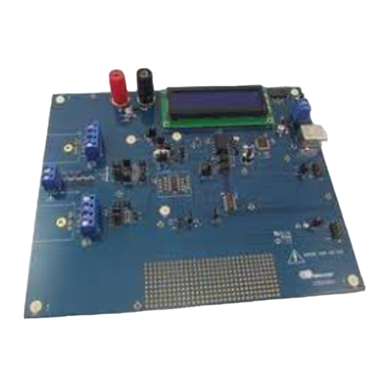
CDB5490U Engineering Board and GUI Software
Features
• Standalone Power Meter Application
• Voltage and Current Interfaces
• Low- and High-voltage Sensor Connections
• Adaptable Sensor Filters Onboard
• USB Communication with PC
• Isolated UART Communication
• Onboard C8051F342 Microcontroller
• Single Supply Operation from USB or an External +5V DC
Supply
• Onboard DC-DC Converter and Regulator
• LCD Power Monitor Display
®
®
• LabWindows
/ CVI
GUI Software
– Full Register Setup and Chip Control
– Simplified Register
– Quick Calibration Control
– FFT Analysis
– Time Domain Analysis
– Noise Histogram Analysis
• Voltage Reference Access
Cirrus Logic, Inc.
http://www.cirrus.com
General Description
The CDB5490U is an extensive tool designed to evaluate the
functionality and performance of Cirrus Logic's CS5490 power
measurement device.
Multiple analog input connection options, configuration input fil-
ters, direct and isolated digital interfaces, multiple power supply
options, an onboard programmable microcontroller, visual LEDs
with an LCD panel make the board a flexible and powerful cus-
tomer development tool for various power measurement
applications.
The GUI software provides easy and complete access and con-
trol to the onboard CS5490 device. In addition, it includes the
function of raw ADC data collection with time domain, frequency
domain, and histogram analysis.
Schematics in PADS™ PowerLogic™ format are available for
download at http://www.cirrus.com/en/support.
ORDERING INFORMATION
CDB5490U-Z
Copyright Cirrus Logic, Inc. 2012
(All Rights Reserved)
CDB5490U
Evaluation Board
APR'12
DS923DB5
Advertisement
Table of Contents

Related Manuals for Cirrus Logic CDB5490U


Summary of Contents for Cirrus Logic CDB5490U
- Page 1 CDB5490U Engineering Board and GUI Software Features General Description • Standalone Power Meter Application The CDB5490U is an extensive tool designed to evaluate the • Voltage and Current Interfaces functionality and performance of Cirrus Logic’s CS5490 power • Low- and High-voltage Sensor Connections measurement device.
- Page 2 CLUDING ATTORNEYS' FEES AND COSTS, THAT MAY RESULT FROM OR ARISE IN CONNECTION WITH THESE USES. Cirrus Logic, Cirrus, the Cirrus Logic logo designs, EXL Core, and the EXL Core logo design are trademarks of Cirrus Logic, Inc. All other brand and product names in this document may be trademarks or service marks of their respective owners.LabWindows and CVI are registered trademarks of National Instruments, Inc.
-
Page 3: Table Of Contents
CDB5490U TABLE OF CONTENTS 1. HARDWARE .............................. 5 1.1 Introduction ............................5 1.2 Evaluation Board Overview ........................ 5 1.3 Analog Section ........................... 6 1.4 Digital Section ............................ 9 1.5 Power Supply Section ........................11 1.6 Typical Sensor Connections ......................12 1.7 Standalone Meter Application ...................... - Page 4 CDB5490U LIST OF FIGURES Figure 1. CDB5490U Assembly Drawing and Default Configuration..............5 Figure 2. Voltage Channel — Low-voltage Input ....................6 Figure 3. Voltage Channel — High-voltage Input ..................... 7 Figure 4. Current Channel — Low-voltage Input ....................8 Figure 5.
-
Page 5: Hardware
The CDB5490U evaluation board provides a convenient means of evaluating the CS5490 energy mea- surement IC. The CDB5490U evaluation board operates from a single USB or 5V power supply. An op- tional 3.3V power supply input is available for powering the CS5490 directly. The evaluation board interfaces the CS5490 to a PC via a USB cable. -
Page 6: Analog Section
CDB5490U Analog Section The analog section of the CDB5490U is highly configurable. Onboard signal conditioning options for the voltage and current channels enable most applications to interface directly to the sensors. The following two sections define the voltage and current channel configurations. -
Page 7: Figure 3. Voltage Channel - High-Voltage Input
It is recommended to apply a 10% margin for the AC line input (270Vrms). The CDB5490U evaluation board provides input shorting options for calibration and noise performance measurements. With a jumper on J6 and J11 in the GND position, the inputs are connected to analog ground (GND). -
Page 8: Figure 4. Current Channel - Low-Voltage Input
IIN- the Input There are two input signal options for the current channel (IIN±). The CDB5490U evaluation board pro- vides screw-type terminals (J1) or XLR connectors (J28) to connect an input signal to the current channel. The screw terminals are labeled as IIN+ / IIN-. An R-C network at the channel input provides a simple, configurable anti-alias filter (see Figure 4). -
Page 9: Digital Section
MCU before serial port communication with the CS5490 (see Figure 5). Figure 5. MCU Connection Window The CDB5490U board provides two UART communication options - normal speed and low speed. Table 3 provides the serial communication options for the UART. - Page 10 1.4.2 Interface to Microcontroller Interface headers J17 and J19 are provided to allow the CDB5490U to be connected to an external energy registration device or an external microcontroller. Interface header J17 provides direct access to the CS5490 pins while interface header J19 provides an isolated connection. It is imperative to use the iso- lated connection (J19) when high-voltage signals are used.
-
Page 11: Power Supply Section
CS5490 analog supply current and must be installed. When connecting the CDB5490U board to the AC line through non-isolated sensors, it is strongly recom- mended that the CS5490 GND reference is connected to the neutral, the non-isolated current sensor is connected on neutral, and the CS5490 is supplied by +3.3V isolated from AC line. -
Page 12: Typical Sensor Connections
CDB5490U Typical Sensor Connections The CDB5490U evaluation board provides connections directly to several types of sensors. Flexible on- board filter networks provide a convenient configuration for three common transducers: current shunt, cur- rent transformer (CT), or Rogowski coil. 1.6.1 Shunt Power Meter Example An inexpensive current shunt configuration is easily achievable with the CDB5490U evaluation board. -
Page 13: Figure 7. Current Transformer Power Meter
Current Transformer Power Meter Example A slightly more expensive option is to use a current transformer (CT) to connect the AC current to the CDB5490U evaluation board. Figure 7 depicts the voltage and current connections for a CT sensor and its associated filter configurations. -
Page 14: Figure 8. Rogowski Coil Power Meter
CDB5490U 1.6.3 Rogowski Coil Power Meter Example Rogowski coil power meter can be easily connected to the CDB5490U evaluation board. Figure 8 shows the voltage and current connections for the Rogowski sensor and its associated filter configurations. CDB5490U IIN+ NO POP 0.033UF... -
Page 15: Standalone Meter Application
12 for details on the sensor connections and “Power Supply Section” on page 11 for details on supply options. The user should not use the GUI to connect the CDB5490U board. Once the GUI is connected to the CDB5490U board, the standalone power meter function is disabled, and the LCD on the CDB5490U will read "Cirrus Logic CS5490 Eval GUI". -
Page 16: Software
3. Click CDB5490U. The GUI is launched. Using the Software Before launching the software, check all jumper settings on the CDB5490U evaluation board, as de- scribed in “Evaluation Board Overview” on page 5, and connect the board to an open USB port on the PC using the provided cable. -
Page 17: Start-Up Window
CDB5490U Start-up Window When the software is launched, the Start-Up Window is displayed. This window contains information about the software, including its title, revision number, and copyright date. The Start-Up Window is dis- played (see Figure 10). Figure 10. GUI Start-up Window At the top of the window, a menu bar with menu items is displayed. -
Page 18: Connect Menu
Figure 12. Connect Menu Showing Successful USB Connection If the evaluation software is unable to establish a communication link with the CDB5490U board, a mes- sage is displayed, indicating that the initial communication has failed (see Figure 13). -
Page 19: System Menu
Verify that the USB cable is connected properly and that the power supply is on and connected properly to the CDB5490U. Reset the board (press the RESET button on the board) and try to set up the USB con- nection again. -
Page 20: Figure 16. Setup Window
CDB5490U 2.5.1 Setup Window The evaluation software provides access to the common CS5490's internal registers through the Setup Window (see Figure 16). The user can enter the Setup Window by selecting the Setup CS5490 item from the System menu. Figure 16. Setup Window In the Setup Window, all of the common CS5490 registers are displayed in hexadecimal notation and are decoded. - Page 21 HEX field, or by changing any of the values below the HEX field to the desired settings. Although the CDB5490U software allows the user to modify any of the bits in the configuration registers, changing certain reserved bits, such as the NO_OSC bit of Config0, may cause the software and board to behave erratically.
- Page 22 The value present in the Mask register may be changed by the GUI software during certain operations to provide correct functionality of the CDB5490U board. 2.5.1.14 Temperature Registers...
-
Page 23: Calibration Window
CDB5490U 2.5.1.16 V Sag, V Swell, and I Overcurrent Registers The registers for voltage sag, voltage swell, and overcurrent are displayed in the V Sag, V Swell, and I Overcurrent Register sections. These sections display the level and duration values of the correspond- ing registers in both hexadecimal and decimal format. - Page 24 CDB5490U The Refresh Screen button will update the contents of the screen by reading all the register values from the part. It is recommended to click the Refresh Screen button when entering the Calibration Window, or after modifying any registers to reflect the current status of the CS5490.
-
Page 25: Conversion Window
CDB5490U Conversion Window The Conversion Window can be accessed from the System menu pull-down, Conversion menu item. The Conversion option requires the CS5490 device to be configured for 2400 or greater baud rate from the Setup Window (see Figure 18). -
Page 26: Figure 20. Conversion Window
CDB5490U status register (Status0, 1, 2) are also displayed. The Conversion Window also provides the total active, apparent and reactive power register results. Figure 20. Conversion Window 2.7.1 Single Conversion Button Pressing the Single Conversion button will cause a single conversion to be performed. After a single con- version is complete, the Result column will be updated with the values present in each data register. -
Page 27: Cirrus Test Window
CDB5490U 2.7.5 Line Frequency Result When the AFC bit in the Config2 register is set, the Epsilon register will be calculated automatically by the CS5490 and the Line Frequency fields will be updated automatically in continuous conversion mode. If the AFC bit in the Config2 register is not set and the line frequency is other than the default value (50Hz), the line frequency must be set manually here to make Epsilon the ratio of line frequency to the output word rate (OWR). -
Page 28: Figure 22. Data Collection Window
CDB5490U 2.8.1 Data Collection Window The Data Collection Window allows the user to collect sample sets of data from the CS5490 and analyze them using time domain, FFT, and histogram plots. The Data Collection window can be accessed by pull- ing down the CirrusTest menu, and selecting the ADC Data Collection item (see Figure 22). -
Page 29: Figure 24. Data Collection Output Window
CDB5490U 2.8.1.4 Output Button The Output button will bring up a window in which the user can output the data to a file for later use, print out a plot, or print out the entire screen. When saving data, only the data channel being displayed on the plot will be saved to a file. -
Page 30: Figure 25. Data Collection Configuration Window
The FFT Window box allows the user to select the type of windowing algorithm for FFT processing. Win- dowing algorithms include the Blackman, Blackman-Harris, Hanning, 5-term Hodie, and 7-term Hodie. The 5-term Hodie and 7-term Hodie are windowing algorithms developed at Crystal Semiconductor, now called Cirrus Logic. 2.8.1.8.4 Histogram Bin Width This field determines the "bin width"... - Page 31 CDB5490U 2.8.1.8.7 Accept Button When the Accept button is pressed, the current settings will be saved and the user will return to the Data Collection window. 2.8.1.9 Collecting Data Sets To collect a sample data set: 1. In the Data Collection window, press the Config button to bring up the Configuration window and view the current settings.
-
Page 32: Figure 26. Histogram Analysis
CDB5490U 2.8.1.11 Histogram Information The following is a description of the indicators associated with histogram analysis. Histograms can be plot- ted in the Data Collection Window by setting the analysis type pull-down menu to Histogram (see Figure 26). The histogram plot information includes: •... -
Page 33: Figure 27. Fft Analysis
CDB5490U 2.8.1.12 Frequency Domain Information The following describe the indicators associated with FFT (Fast-Fourier Transform) analysis. FFT data can be plotted in the Data Collection window by setting the analysis type selector to FFT (see Figure 27). The FFT information includes: •... -
Page 34: Figure 28. Data Collection Window - Time Domain Analysis
CDB5490U 2.8.1.13 Time Domain Information The following controls and indicators are associated with time domain analysis. Time Domain data can be plotted in the Data Collection window by setting the analysis type selector to Time Domain (see Figure 28). The Time Domain plot includes: •... -
Page 35: Figure 29. Data Collection To File Window
CDB5490U 2.8.2 Data Collection to File Window The Data Collection to File window allows the user to collect instantaneous voltage and current register data over an extended period of time to a data file (see Figure 29). The Data Collection to File option re- quires the CS5490 device to be configured at the maximum baud rate set from the within the Setup Win- dow (see Figure 18). -
Page 36: Figure 30. Setup And Test Window
CDB5490U 2.8.3 Setup and Test Window The Setup and Test window allows the user a way to access CS5490 registers and send commands to the CS5490 directly (see Figure 30). Figure 30. Setup and Test Window There are three types of transactions: Write register, Read register, and Send command. The CS5490 memory is organized by pages. -
Page 37: Appendix A. Bill Of Materials
APPENDIX A. BILL OF MATERIALS CIRRUS LOGIC BILL OF MATERIAL CDB5490U_REV_B.bom Status Item Cirrus P/N Description Reference Designator MFG P/N Notes 001-02194-Z1 CAP 0.1uF ±10% 25V X7R NPb 0603 C1 C2 C7 MURATA GRM188R71E104KA01D NO POP 001-10064-Z1 CAP 15pF ±5% 50V C0G NPb 0603... -
Page 38: Figure 32. Bill Of Materials
DIODE TR 6.8V 600W NPb AXL Z1 Z2 LITTELFUSE P6KE6.8 070-00200-Z1 DIODE TVS 3.3V 2LN ESD NPb SOT23 COMCHIP CTES033V3-G ECO853 TECHNOLOGY 603-00483-Z1 ASSY DWG CDB5490U-Z-NPb CIRRUS LOGIC 603-00483-Z1 ECO813,ECO853 240-00483-Z1 PCB CDB5490U-Z-NPb CIRRUS LOGIC 240-00483-Z1 ECO813.ECO853 600-00483-Z1 SCHEM CDB5490U-Z-NPb... -
Page 39: Appendix B. Schematics
VIN- VIN- VIN- HDR2X2 NOTES: UNLESS OTHERWISE SPECIFIED: PART # 600-00483-Z1 REV C2 1. ALL RESISTOR VALUES ARE IN OHMS. DESCRIPTION: SCHEM CDB5490U-Z NPb SHEET TITLE: ANALOG INPUTS DRAWN BY: Alan ZHA ENGINEER: Alan ZHA SIZE B DATE: 02/17/11 SHEET... -
Page 40: Figure 34. Schematic - Cs5490 And Isolation
PART # 600-00483-Z1 REV C2 ELEC 47uF 0.1uF ASSY DWG- 603-00483-Z1 0.1uF DESCRIPTION: SCHEM CDB5490U-Z NPb PCB DWG- 240-00483-Z1 600-00483-Z1 SCHEMATIC DWG LBL SUBASSY PROD ID AND REV SHEET TITLE: CS5490+ISOLATION WIRE HOOK UP #6AWG STR BLU NPb L-1.5X.25TX.25T_TYPE_E_ SOCKET 1P-... -
Page 41: Figure 35. Schematic - Microcontroller And Usb Interface
GND1 GND1 GND1 GND1 0.1uF GND1 GND1 NO POP GND1 PART # 600-00483-Z1 REV C2 DESCRIPTION: SCHEM CDB5490U-Z NPb SHEET TITLE: MCU+LCD+USB GND1 GND1 DRAWN BY: Alan ZHA ENGINEER: Alan ZHA SIZE B DATE: 02/17/11 SHEET Figure 35. Schematic - Microcontroller and USB Interface... -
Page 42: Appendix C. Layer Plots
APPENDIX C. LAYER PLOTS Figure 36. Top Silkscreen... -
Page 43: Figure 37. Top Routing
Figure 37. Top Routing... -
Page 44: Figure 38. Bottom Routing
Figure 38. Bottom Routing... -
Page 45: Figure 39. Solder Paste Mask
Figure 39. Solder Paste Mask... - Page 46 CDB5490U REVISION HISTORY Revision Date Changes APR 2011 Initial Release. DEC 2011 Updated screen shots and circuit diagrams to align with B0 silicon. JAN 2012 Corrected typographical errors. MAR 2012 Updated content. APR 2012 Updated screen shots and circuit diagrams to align with B2 silicon.
Need help?
Do you have a question about the CDB5490U and is the answer not in the manual?
Questions and answers