
Related Manuals for Cirrus Logic EDB9315A


Summary of Contents for Cirrus Logic EDB9315A
- Page 1 EP9315 Enhanced Universal Platform System-on-Chip Processor EDB9315A Engineering Development Board Technical Reference Manual © Copyright 2006 Cirrus Logic, Inc. AUG ’06 DS638DB3 http://www.cirrus.com...
-
Page 2: Corporate Headquarters
Fax: +81 (3) 5226-7677 EUROPE Cirrus Logic (UK) Ltd. Park House, Mere Park, Dedmere Road Marlow, Bucks, SL7 1FJ, England Phone ++49 89 818 974 65 Switchboard +44 1628 891300 Fax +44 1628 891988 © Copyright 2006 Cirrus Logic, Inc. DS638DB3... -
Page 3: Table Of Contents
1. EDB9315A Kit Contents ............5 2. Introducing the EDB9315A Engineering Development Board ..... . . 6 2.1 Identifying What's on the Board . - Page 4 EDB9315A Technical Reference Manual List of Figures Figure 1. EDB9315A Board........................5 Figure 2. EDB9315A Top View .........................7 Figure 3. Block Diagram..........................10 Figure 4. Schematic Page 1 - Block Diagram ..................19 Figure 5. Schematic Page 2 - Processor & Memory ................20 Figure 6.
-
Page 5: Edb9315A Kit Contents
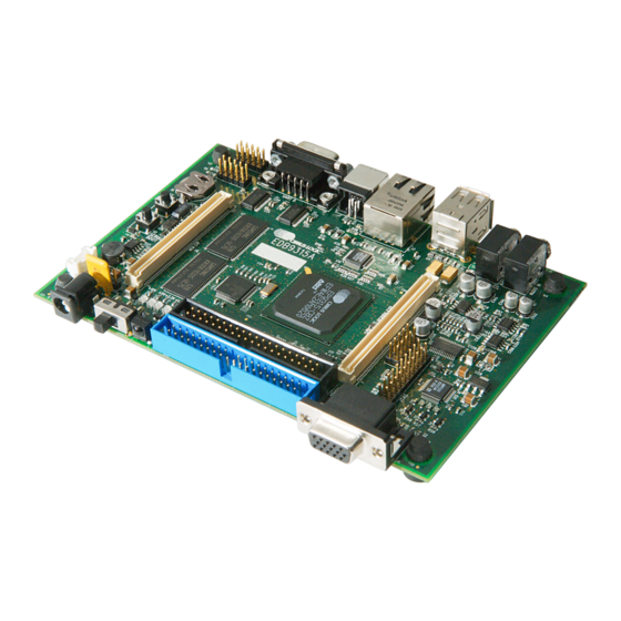
• Quick Start Guide • Board Registration Card • Trial Software Download Information Card All documentation, schematics, software, utilities, and related information is available from the download section of the Cirrus Logic ARM Developer's web site, http://arm.cirrus.com. Figure 1. EDB9315A Board © DS638DB3... -
Page 6: Introducing The Edb9315A Engineering Development Board
• Expansion Connectors • LCD Interface with Touch Screen Support Note: The EDB9315A kit does not include a LCD screen. The LCD interface is pin-compatible with previous Cirrus Logic development boards. Not all features of the EP9315 are on the base board. Two high-density connectors have been provided to allow for daughter card expansion. -
Page 7: Figure 2. Edb9315A Top View
One item not listed above is the Flash device. It is located on the bottom side of the board, under item C. There are no jumpers on the board. The only "jumper" is the serial boot pushbutton. This button is used when the developer wants to use the Cirrus Logic download utility to put new code into Flash memory. ©... -
Page 8: Getting Started
PCB for the pin 1 location. The pin 1 identifier is marked by either a number or a triangle. 3.3 Before Applying Power... In order to use the EDB9315A the user must first connect the peripherals to the EDB9315A as described in the following procedure. 1. Place the EDB9315A on a static free surface. - Page 9 NOTE: The WinCE 5.0 binary is not provided on the support web site. If you erase the image on the board, you will have to download the BSP provided by Cirrus Logic and compile it using Platform Builder. Due to changes in distribution policy, the Microsoft trial CD/DVD that was formerly included in the kit is no longer available.
-
Page 10: Edb9315A Circuit Description
Technical Reference Manual 4. EDB9315A Circuit Description This chapter makes reference to the schematics in Appendix A and discusses the main circuit functionality of each schematic page. A detailed block diagram of the EDB9315A Engineering Development Board is shown below. JTAG... -
Page 11: Circuit Operation
Two such cables are included with the kit. All UART signals are level shifted from TTL to RS-232. The CIR uses an enhanced GPIO (EGPIO) line to communicate to the EP9315 device. © DS638DB3 Copyright 2006 Cirrus Logic, Inc. -
Page 12: Circuit Description, Schematic
The “Serial Boot” pushbutton, S2, is used to configure the board to perform a serial boot. A serial boot is used to program the Flash device with the Cirrus Logic download utility. Instead of using jumpers, a pushbutton is used. Simply hold the pushbutton down while pressing and releasing the reset pushbutton, S3. -
Page 13: Circuit Description, Schematic
However if a CPLD or FPGA is attached there is no reason to buffer. Use proper engineering practices when using the high-speed memory bus with daughter cards. The Peripheral Expansion bus has the signals for features not implemented on the EDB9315A board and for commonly used signals. -
Page 14: Circuit Description, Schematic
Power and reset circuits are shown on this page. Most of the changes made to this revision of the EDB9315A board were made in this section. The most important change made is that the board is now powered from a +12V power supply instead of the former +5V supply. -
Page 15: Software
WinCE 5.0 Flash image with Linux or some other software, and then later desires to put the WinCE 5.0 image back into Flash, they must obtain the WinCE 5.0 BSP from their Cirrus Logic FAE and build the image themselves using the trial version of Platform Builder™ or with a version of Platform Builder they have purchased. -
Page 16: Developer's User Forum
EDB9315A Technical Reference Manual 6. Developer’s User Forum Many references have been made to the Cirrus Logic Developers User's Forum in this document. The Cirrus Logic Developers User's Forum is a company-sponsored site and moderated by Cirrus Logic ® employees. However, it is not the technical help line for the Cirrus Logic ARM product line. -
Page 17: Other Useful Information
• Linux 2.6 • Board utilities • Tools Contact a Cirrus Logic FAE for information regarding the following. • WinCE 5.0 BSP The documents listed above are updated periodically and may be more up to date than the information in this document. -
Page 18: Appendix A. Schematics
EDB9315A Technical Reference Manual Appendix A. Schematics The schematics for the EDB9315A Development Board are located on the Cirrus Logic Developer’s Forum website ( arm.cirrus.com ). The schematics are provided in Adobe’s portable document format (PDF) and PADS™ format. OrCAD™ versions of the schematics are not available. -
Page 19: Figure 4. Schematic Page 1 - Block Diagram
EDB9315A Technical Reference Manual © DS638DB3 Copyright 2006 Cirrus Logic, Inc. -
Page 20: Figure 5. Schematic Page 2 - Processor & Memory
EDB9315A Technical Reference Manual © Copyright 2006 Cirrus Logic, Inc. DS638DB3... -
Page 21: Figure 6. Schematic Page 3 - Peripherals
EDB9315A Technical Reference Manual © DS638DB3 Copyright 2006 Cirrus Logic, Inc. -
Page 22: Figure 7. Schematic Page 4 - Uarts & Usb
EDB9315A Technical Reference Manual © Copyright 2006 Cirrus Logic, Inc. DS638DB3... -
Page 23: Figure 8. Schematic Page 5 - Mp Power
EDB9315A Technical Reference Manual © DS638DB3 Copyright 2006 Cirrus Logic, Inc. -
Page 24: Figure 9. Schematic Page 6 - Sdram & Flash
EDB9315A Technical Reference Manual © Copyright 2006 Cirrus Logic, Inc. DS638DB3... -
Page 25: Figure 10. Schematic Page 7 - Jtag & Cfg
EDB9315A Technical Reference Manual © DS638DB3 Copyright 2006 Cirrus Logic, Inc. -
Page 26: Figure 11. Schematic Page 8 - Ethernet
EDB9315A Technical Reference Manual © Copyright 2006 Cirrus Logic, Inc. DS638DB3... -
Page 27: Figure 12. Schematic Page 9 - Expansion Connector
EDB9315A Technical Reference Manual © DS638DB3 Copyright 2006 Cirrus Logic, Inc. -
Page 28: Figure 13. Schematic Page 10 - Ide
EDB9315A Technical Reference Manual © Copyright 2006 Cirrus Logic, Inc. DS638DB3... -
Page 29: Figure 14. Schematic Page 11 - Vga & Lcd
EDB9315A Technical Reference Manual © DS638DB3 Copyright 2006 Cirrus Logic, Inc. -
Page 30: Figure 15. Schematic Page 12 - Usb2.0 Slave
EDB9315A Technical Reference Manual © Copyright 2006 Cirrus Logic, Inc. DS638DB3... -
Page 31: Figure 16. Schematic Page 13 - Audio
EDB9315A Technical Reference Manual © DS638DB3 Copyright 2006 Cirrus Logic, Inc. -
Page 32: Figure 17. Schematic Page 14 - Power Supply
EDB9315A Technical Reference Manual © Copyright 2006 Cirrus Logic, Inc. DS638DB3... -
Page 33: Appendix B. Programming Linux Images Into Flash From A Windows® Pc
The instructions and screen shots in this Appendix make reference to the SolarWinds 6.0 TFTP server program. This program is not provided by Cirrus Logic. Other TFTP server programs may work equally well but will need to be verified by the developer. -
Page 34: Downloading Files
When done, click on OK and then OK again for changes to take effect. Note: The IP address can be any address you chose, just make sure it matches the IP address you use in the fconfig step below. © Copyright 2006 Cirrus Logic, Inc. DS638DB3... -
Page 35: Tftp Server Setup (Setup May Vary Depending On Tftp Server Used)
3. Once the program is installed, run the TFTP Server program. 4. Configure the TFTP Root directory to point to C:\TFTPROOT. 5. Select the Security Tab and make sure the Client access is Transmit and Receive files. See the pictures below. © DS638DB3 Copyright 2006 Cirrus Logic, Inc. - Page 36 Note: Note: You may get an IP address of 127.0.0.1 because the EDB9315A board does not have the boot loader code programmed yet. This is ok. Simply quit the TFTP server program. Instructions on when to start the program will be given during the board programming section.
-
Page 37: Hyperterminal Setup
(1) stop bit (8-N-1) and NO hardware control flow. It should look like the picture below when complete. Note you have to "Disconnect" in order to make configuration changes. Click "Call" once the configuration is complete. © DS638DB3 Copyright 2006 Cirrus Logic, Inc. -
Page 38: Board Programming Setup
Board Programming Setup 1. At this point, the RJ45 Ethernet port on the Windows PC is configured, HyperTerminal is running, the TFTP server is running, the Cirrus Logic software has been downloaded to the C:\TFTPROOT directory and the board is powered up. - Page 39 EDB9315A Technical Reference Manual download.exe Downloading the Code download.exe Erasing then Programming the Flash Memory download.exe Successfully Programming redboot.bin © DS638DB3 Copyright 2006 Cirrus Logic, Inc.
- Page 40 6. The next step is to configure the board so it can communicate via Ethernet. Type "fconfig" in the HyperTerminal window and set all parameters like the picture below. Note: You may have to hit the Backspace key to change some parameters and then type in the new parameter. © Copyright 2006 Cirrus Logic, Inc. DS638DB3...
- Page 41 9. Press and release pushbutton S3 "/POR" for the changes to take effect. You should see the following. Note: It will say "No image 'image_name' found". That is ok for now. We have not downloaded and programmed those images into Flash yet © DS638DB3 Copyright 2006 Cirrus Logic, Inc.
- Page 42 The size can be determined from the reported status after the load. Simply subtract the end address from the start address. It is acceptable to make the partition larger than the exact image file size. © Copyright 2006 Cirrus Logic, Inc. DS638DB3...
- Page 43 EDB9315A Technical Reference Manual Once the board has been programmed, reset the board and wait for it to boot up. You will see the following (or similar) screen on the display.. © DS638DB3 Copyright 2006 Cirrus Logic, Inc.
-
Page 44: Revision History
ANY AND ALL LIABILITY, INCLUDING ATTORNEYS' FEES AND COSTS, THAT MAY RESULT FROM OR ARISE IN CONNECTION WITH THESE USES. Cirrus Logic, Cirrus, and the Cirrus Logic logo designs are trademarks of Cirrus Logic, Inc. All other brand and product names in this document may be trademarks or service marks of their respective owners. - Page 45 Mouser Electronics Authorized Distributor Click to View Pricing, Inventory, Delivery & Lifecycle Information: Cirrus Logic EDB9315A-Z...
Need help?
Do you have a question about the EDB9315A and is the answer not in the manual?
Questions and answers