Table of Contents
Advertisement
Quick Links
Features
Asynchronous Sample Rate Conversion
Input to output conversion ratio as large as
1:3 or 3:1
Receives and transmits AES/EBU, S/PDIF
and EIAJ-340 compatible digital audio
Runs from a single 5 Volt supply.
Crystals are supplied to allow operation at
44.1 kHz, 48 kHz, and 96 kHz output sample
rates.
Digital patch area.
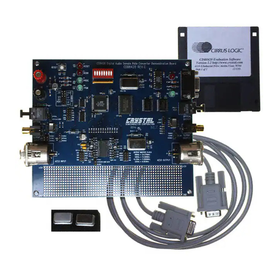
I
Optical In
S/PDIF In
AES 3 In
Preliminary Product Information
http://www.cirrus.com
Evaluation Board for CS8420
Amtel
µC
CS8420
This document contains information for a new product.
Cirrus Logic reserves the right to modify this product without notice.
Copyright
(All Rights Reserved)
Description
The CDB8420 is designed to allow rapid evaluation of
the CS8420. Because of the high performance of the
CS8420, the board is set up for easy connection to an
Audio Precision or a Rohde and Schwarz test system.
Currently available A/D and D/A converters are not ade-
quate to test the full performance of the device.
Input and output data may independently be set to either
AES/EBU or S/PDIF in optical or coaxial physical
formats.
Windows 98 PC software provides a GUI interface to
make configuration easy. The software communicates
through the PC's RS232 port to a micro-controller on the
evaluation board that controls the CS8420. All the possi-
ble software modes of the CS8420 may be tested.
ORDERING INFORMATION
CDB8420
Cirrus Logic, Inc. 2003
CDB8420
Evaluation Board
RS232 port to PC
Optical Out
S/PDIF Out
AES 3 Out
Dec '03
DS245DB4
1
Advertisement
Table of Contents

Subscribe to Our Youtube Channel
Related Manuals for Cirrus Logic CDB8420


Summary of Contents for Cirrus Logic CDB8420
- Page 1 S/PDIF In S/PDIF Out AES 3 In AES 3 Out This document contains information for a new product. Preliminary Product Information Cirrus Logic reserves the right to modify this product without notice. Copyright Cirrus Logic, Inc. 2003 Dec ‘03 http://www.cirrus.com...
-
Page 2: Table Of Contents
3.2 Board Setup ........................7 3.3 Script file syntax ......................... 7 LIST OF FIGURES Figure 1. CDB8420 Control Panel Main Window ................6 Figure 2. Board Setup Panel ......................7 Figure 3. CS8420 Sample Rate Converter..................8 Figure 4. Atmel AVR RISC Micro-controller ..................9 Figure 5. -
Page 3: Overview
CDB8420 OVERVIEW The CDB8420 evaluation board contains a CS8420 placed. The oscillator labeled U10 provides the 6 and the supporting circuitry necessary for it to op- MHz clock for the micro-controller and should not erate. The input and output options include AES3 be changed. -
Page 4: Table 1. System Connections
Specifies output as coaxial S/PDIF Enables S/PDFIF OUTPUT ENABLE S/PDIF OUTPUT enabled DISABLE S/PDIF OUTPUT disabled Enables HARDWARE MODE MUTE ENABLE Enables MUTE when in hardware mode 1 DISABLE Disables MUTE when in hardware mode 1 Table 2. CDB8420 Jumper Settings DS245DB4... -
Page 5: Cdb8420.Exe Quick Start Guide
1) Double-click on CDB8420.exe or its shortcut. Setting up the hardware: 2) If you get errors right away, the COM port 1) Connect the CDB8420 to a 5V DC power sup- needs to be set properly. ply. 3) Click anywhere but inside one of the boxes, this 2) Set: J11 to Optical, J16 to S/PDIF, enable J13 brings up the Board Setup control panel. -
Page 6: Cdb8420.Exe User's Guide
This Main Window will display a control panel for the selected block. The CDB8420 Control Panel allows you to view If you click outside the boxes, you will bring up the and access the data flow configuration of the Board Setup control panel, as shown on the next CS8420. -
Page 7: Board Setup
CDB8420 Board Setup NOTE: Most commands accept either hexadecimal (indicated by either a "0x" prefix or "h" suffix) or The Board Setup panel has some very useful func- decimal parameters. tions, including setting the COM Port used by the application, resetting the CS8420 by the software, used for single line comments as well as loading/saving register settings into files. -
Page 8: Figure 3. Cs8420 Sample Rate Converter
CDB8420 DS245DB4... -
Page 9: Figure 4. Atmel Avr Risc Micro-Controller
CDB8420 DS245DB4... -
Page 10: Figure 5. Power Supplies And Reset Circuit
CDB8420 DS245DB4... -
Page 11: Figure 6. Silkscreen
CDB8420 DS245DB4... -
Page 12: Figure 7. Top Pcb
CDB8420 DS245DB4... -
Page 13: Figure 8. Bottom Pcb
CDB8420 DS245DB4... - Page 14 ATTORNEYS’ FEES AND COSTS, THAT MAY RESULT FROM OR ARISE IN CONNECTION WITH THESE USES. Cirrus Logic, Cirrus, and the Cirrus Logic logo designs are trademarks of Cirrus Logic, Inc. All other brand and product names in this document may be trademarks or service marks of their respective owners.
Need help?
Do you have a question about the CDB8420 and is the answer not in the manual?
Questions and answers