
Related Manuals for Fire-Lite Alarms MS-5024

Summary of Contents for Fire-Lite Alarms MS-5024
- Page 1 PN: 50066:D2 ECN 02-606 Fire Control Communicator MS-5024/MS-5024E Document #50066 12/03/02 Rev.
- Page 2 While a fire alarm system may lower insurance Fire Alarm System Limitations rates, it is not a substitute for fire insurance! An automatic fire alarm system–typically made up of smoke Heat detectors do not sense particles of combustion and detectors, heat detectors, manual pull stations, audible warn- alarm only when heat on their sensors increases at a prede- ing devices, and a fire alarm control with remote notification termined rate or reaches a predetermined level.
-
Page 3: Installation Precautions
Installation Precautions Adherence to the following will aid in problem-free installation with long-term reliability: WARNING - Several different sources of power can be con- Like all solid state electronic devices, this system may nected to the fire alarm control panel. Disconnect all sources operate erratically or can be damaged when subjected to light- of power before servicing. - Page 4 Notes Document #50066 Rev.D2 12/03/02 P/N 50066:D2...
-
Page 5: Table Of Contents
Table of Contents CHAPTER 1: Product Description ......................... 11 1.1: Product Features ............................11 FIGURE 1-1: DP-5024 ........................12 FIGURE 1-2: MS-5024 Control Panel....................12 1.2: Controls and Indicators ..........................13 1.2.1: Front Panel Switches ........................13 FIGURE 1-3: Controls and Indicators ....................13 1.2.2: Display and Indicators ........................13 1.2.3: Local Sounder ...........................13... - Page 6 Table of Contents FIGURE 2-8: Typical Wiring Diagram for UL Power-limited Requirements ........26 2.7: Digital Communicator ..........................27 FIGURE 2-9: Wiring Phone Jacks .......................27 2.8: Optional Boards............................28 2.8.1: ADM-24 Annunciator Driver Module ....................28 FIGURE 2-10: ADM-24 ........................28 2.8.2: RZA-5F Remote Annunciator......................28 FIGURE 2-11: RZA-5F ........................28 FIGURE 2-12: Wiring the RZA-5F/ADM-24 ..................29 FIGURE 2-13: Installing Annunciator in Single-Gang Box..............29...
- Page 8 Notes Document #50066 Rev.D2 12/03/02 P/N 50066:D2...
- Page 9 This control panel has been designed to comply with standards set forth by the following regulatory agencies: • Underwriters Laboratories Standard UL 864 • NFPA 72 National Fire Alarm Code for Local, Remote Station and Central Station Fire Alarm Systems •...
- Page 10 Secondary Transformer Connector Note: When dressing wires, maintain a minimum of 0.25" distance between conductors to power-limited and nonpower-limited circuits. Document #50066 Rev.D2 12/03/02 P/N 50066:D2...
-
Page 11: Chapter 1: Product Description
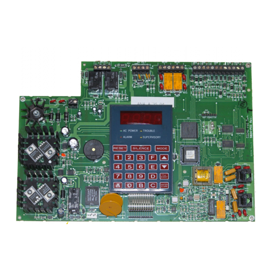
Product Description CHAPTER 1 The MS-5024 is a combination control panel and digital communicator all on one circuit board. It is a five-zone panel which uses conventional input devices. The panel accepts waterflow devices, two-wire smoke detectors, four- wire smoke detectors, pull stations and other normally open contact devices. Outputs include two NACs (Notifica- tion Appliance Circuits) and two programmable relays. - Page 12 • One-man Walktest • Optional Dead Front cover (DP-5024) • CAC-5F Class A Converter module for Initiating Device Circuits • NACA-2F Class A Converter module for Notification Appliance Cir- cuits MS-5024 Control Panel FIGURE 1-2: Notification Programmable 5 Input Appliance...
-
Page 13: Controls And Indicators
Controls and Indicators Controls and Indicators 1.2.1 Front Panel Switches Controls and Indicators FIGURE 1-3: RESET Digits 0 - 9 SILENCE MODE Up Arrow Down Arrow 1st EVENT ENTER/STORE 1.2.2 Display and Indicators • Four 7-Segment Displays - red • Alarm - red LED •... -
Page 14: 3: Notification Appliance Circuits
Digital Communicator 1.3.3 Notification Appliance Circuits Two NACs (Notification Appliance Circuits) configurable for Style Y (Class B) with various programmable features. 1.3.4 Relays Two dry Form-C relay contacts programmable for Alarm, Trouble, Supervisory and/or Communications Failure. Contacts are rated 2 amps @ 30 VDC (resistive) and 0.5 amps @ 30 VAC (resistive). Digital Communicator Two modular phone jacks allow easy connection to telephone lines. -
Page 15: 4: Batteries
Optional Devices 1.5.4 Batteries The cabinet provides space for 7 Amp Hour batteries (for 12 Amp Hour to 18 Amp Hour batteries use the UL listed BB-17F battery box). Batteries must be ordered separately. Optional Devices 1.6.1 ADM-24 The ADM-24 Annunciator Driver Module supports the RZA-5F Remote Annunciator module. Annunciator wiring is supervised for open circuits by this module. -
Page 16: 6: Bb-17F
Battery (lead acid only) - J1 Maximum charging circuit: Normal Flat Charge - 27.6V @ 0.8 amp Maximum charger capacity: 17 Amp Hour battery (MS-5024 cabinet holds maximum 7 Amp Hour battery. Larger batteries require Fire•Lite BB-17F or other UL listed battery cabinet). -
Page 17: Telephone Requirements And Warnings
The following information is provided if required by the local telephone company: Manufacturer: Fire•Lite Alarms, Inc. One Fire-Lite Place Northford, CT 06472 Product Model Number: MS-5024 FCC Registration Number: 1W6USA-20004-AL-E Ringer Equivalence: 1.3B Note: The FCC ID label is located on the inside of the control panel door. -
Page 18: 4: For Canadian Applications
Telephone Requirements and Warnings When the control panel activates, premises phones will be disconnected. Two separate phone lines are required. Do not connect both telephone interfaces to the same telephone line. The control panel must be connected to the public switched telephone network upstream of any private telephone system at the protected premises. -
Page 19: Chapter 2: Installation
Installation Installation CHAPTER 2 Mounting Options The cabinet may be either semi-flush or surface mounted. The door is removable during the installation period by opening and lifting off the hinges. The cabinet mounts using two key slots and two additional 0.250" diameter holes located in the backbox. - Page 20 Backbox Mounting Draw wires through the respective knockout locations. Cabinet Dimensions and Knockout Locations FIGURE 2-1: 10.125“ (25.718 cm) 8.125“ (20.638 cm) 6.125“ (15.558 cm) 1.125“ 0.875“ 4.125“ (10.478 cm) (2.858 cm) (2.223 cm) 1.25“ (3.175 cm) 3.000“ (7.620 cm) Right Side 1.25“...
- Page 21 Mount the MS-5024 cabinet to the wall Remove appropriate knockouts from the MS-5024 cabinet and BB-17F Position the BB-17F near the MS-5024 cabinet and connect with conduit, making sure there is at least ½" of clearance between the two cabinets...
-
Page 22: Operating Power
Primary Power Source (AC) and Earth Ground Connections AC power connections are made inside the control panel cabinet. Primary power source for the MS-5024 is 120VAC, 60 Hz, 1.2 amps and for the MS-5024E is 220/240VAC, 50 Hz, 0.6 amps. Run a pair of wires (with ground conductor) from the protected premises main breaker box to the orange and black primary leads of the MS-5024 transformer. -
Page 23: Input Circuits
UL listed compatible 2-wire smoke detector UL listed compatible 2-wire smoke detector Manual Pull Station Manual Pull Station Heat Detector Heat Detector Dummy load all unused circuits with a 4.7K ELR (P/N 71245) across B+ and B- MS-5024 Document #50066 Rev. D2 12/03/02 P/N 50066:D2... -
Page 24: Output Circuits
2.5.3 Notification Appliance Circuits (full-wave rectified) The MS-5024 provides two Style Y NACs (Notification Appliance Circuits), each capable of 1.5 amps of current. Total current drawn from these as well as other DC power outputs cannot exceed 3.6 amps. Circuits are supervised and power-limited. -
Page 25: 4: Programmable Relays
Output Circuits Note that both NACs may be programmed as follows: • Silenceable • Nonsilenceable • Enabled/Disabled • Silence Inhibited • Autosilence, 5 to 30 minutes • Coded (March Time, Temporal, California) 2.5.4 Programmable Relays The control panel provides two sets of Form-C programmable relay contacts rated for 2.0 amps @ 30 VDC (resistive). -
Page 26: Ul Power-Limited Wiring Requirements
0.25" away from any nonpower-limited circuit wiring. Furthermore, all power-limited circuit wiring and nonpower-limited circuit wiring must enter and exit the cabinet through different knockouts and/or conduits. A typical wiring diagram for the MS-5024 is shown below. Typical Wiring Diagram for UL Power-limited Requirements... -
Page 27: Digital Communicator
Digital Communicator Digital Communicator Two independent telephone lines can be connected to the control panel. Telephone line control/command is made possible via double line seizure as well as usage of an RJ31X style interconnection. The control panel’s digital com- municator is built into the main circuit board. Connection and wiring of two phone lines is required as shown below. Note that it is critical that the digital communicator be located as the first device on the incoming telephone circuit to properly function. -
Page 28: Optional Boards
Optional Boards Optional Boards 2.8.1 ADM-24 Annunciator Driver Module The ADM-24 supports the RZA-5F Remote Annunciator. The wiring is supervised for open conditions by this mod- ule. The Annunciator Driver Module mounts to J3 in the upper right corner of the main circuit board. ADM-24 FIGURE 2-10: ADM-24... - Page 29 Optional Boards Wiring the RZA-5F/ADM-24 FIGURE 2-12: +24V Note: Make wiring connections with system power off. Maximum wire ADM-24 impedance is 100 ohms per wiring connection. RZA-5F Installing Annunciator in Single-Gang Box FIGURE 2-13: screw #6-32 x 1.00" LG Document #50066 Rev.
-
Page 30: 3: Naca-2F And Cac-5F Class A Converter Modules
The NACA-2F module is used to convert the two Style Y (Class B) Notification Appliance Circuits to two Style Z (Class A) NACs. The module connector J1 is inserted into the terminals of terminal block TB5 on the MS-5024 and the terminal screws are tightened to secure the module. -
Page 31: Chapter 3: Programming Instructions
Programming Instructions Programming Instructions CHAPTER 3 This chapter describes programming the panel from the onboard keypad. Programming of the control panel is possible at any time except when an alarm condition is present or during a fire drill. The control panel has been designed for many different types of applications. After examining your specific application, review the programming options and choose the entries best suited for your system. -
Page 32: Switch (Key) Functions
Switch (Key) Functions Note that location 56 is factory defaulted to '0' for control panel only. This keeps the communicator off until location 56 is changed to '1' for slave communicator or '2' for panel/communicator. Once location 56 is set to '1' or '2' and a valid phone number is entered, entry into the Program Mode will cause transmission of the 'system off-normal' report. - Page 33 Programming Options Primary Central Station Number Communication Format (16) One location is needed to select the Communication Format for the primary phone number. Address 16 is used for this purpose. The default (factory setting) for this address is 'A' (16_A), which is 4+2 Standard, 1800 Hz 'Carrier', 2300 Hz 'ack'.
- Page 34 Programming Options 3+1, 4+1 Express, 4+1 Standard and Expanded, 4+2 Expanded - Primary TABLE 3-1: Address Description Setting Primary # Zone 5 Fault Code Primary # Earth Fault Code Primary # Low Battery Fault Code Primary # No Battery Fault Code Primary # Telco Primary Line Fault Code Primary # Telco Secondary Line Fault Code Primary # NAC #1 Fault Code...
- Page 35 Programming Options 4+2 Standard and 4+2 Express Format If '1, A or C' is entered for address 16, the data in Table 3-2 is automatically programmed for the Primary Central Station phone number event codes. Enter '00' for the setting to disable the report. 4+2 Standard and 4+2 Express Format - Primary TABLE 3-2: Address...
- Page 36 Programming Options Primary Central Station Number Account Code (17-20) Four locations at addresses 17-20 default to all '0s.' Valid entries are '0-9' and 'A-F,' The number of digits entered must match the format selection. If programming '2, 3, 4 or 5' into address 16, enter three digits (location 20 is not used).
- Page 37 Programming Options Secondary Central Station Number Communication Format (42) One location is needed to select the Communication Format for the secondary phone number. Address 42 is used for this purpose. The default (factory setting) for this address is 'A' (42_A), which is 4+2 Standard, 1800 Hz 'Carrier', 2300 Hz 'ack'.
- Page 38 Programming Options 3+1, 4+1 Express, 4+1 Standard and Expanded, 4+2 Expanded - Secondary TABLE 3-3: Address Description Setting Secondary # Zone 5 Fault Code Secondary # Earth Fault Code Secondary # Low Battery Fault Code Secondary # No Battery Fault Code Secondary # Telco Primary Line Fault Code Secondary # Telco Secondary Line Fault Code Secondary # NAC #1 Fault Code...
- Page 39 Programming Options 4+2 Standard and 4+2 Express Format If '1, A or C' is entered for address 42, the data in Table 3-4 is automatically programmed for the Secondary Central Station phone number event codes. Enter '00' for the setting to disable the report. 4+2 Standard and 4+2 Express Format - Primary TABLE 3-4: Address...
- Page 40 Programming Options Secondary Central Station Number Account Code (43-46) Four locations at addresses 43-46 default to all '0s.' Valid entries are '0-9' and 'A-F,' The number of digits entered must match the format selection. If programming '2, 3, 4 or 5' into address 42, enter three digits (location 46 is not used).
-
Page 41: Table 3-5
Programming Options Programmable Relay #1 (53) Programmable Relay #1 may be programmed to activate on alarm, trouble, supervisory, communication failure or any combination of the four conditions. The default (factory) setting for this address is '1' for activation on alarm only. - Page 42 Programming Options Zone 1 Function Selection (57) Factory default for zone 1 is '0' for 2-wire smoke detector. Enter '1' for pull station, '2' for normally open contact device, '3' for supervisory or '4' for supervisory autoresettable. Zone 2 Function Selection (58) Factory default for zone 2 is '0' for 2-wire smoke detector.
- Page 43 Programming Options Alarm Presignal (65) Positive Alarm Sequence is used to delay Notification Appliance Circuit(s) activation while allowing for visual veri- fication by a person. Once a zone triggers an alarm, the mainboard piezo and the annunciator piezo turn on steady, the display indicates the activated zone, the alarm LED blinks and the Notification Appliance Circuits are held off for 15 seconds.
- Page 44 Programming Options Coding Notification Appliance Circuit #2 (76) Coding of Notification Appliance Circuit #2 can be programmed by selecting '1' for March Time (120 ppm), '2' for California (10 seconds On, 5 seconds Off) or '3' for Temporal (½ second On, ½ second Off, ½ second On, ½ second Off, ½...
- Page 45 Programming Options Note that the software for the MS-5024 operates the internal clock based upon 60 Hz. The software for the MS-5024E operates the internal clock based upon 50 Hz. End Programming Exit Programming Mode by pressing the MODE key, followed by the 4-digit code corresponding to an alternate mode of operation, then press the [ENTER/STORE] key.
-
Page 46: Chapter 4: Operating Instructions
Operating Instructions Operating Instructions CHAPTER 4 The MS-5024 has five modes of operation; Normal, Program, Walktest, Troubleshoot and History. Upon initial power-up, the system will be in Normal Mode. This chapter discusses operation of the control panel in the Normal Mode. -
Page 47: 3: Mode
Display and LEDs Upon the occurrence of a subsequent event (alarm or trouble), System Silence is overridden and the control panel will respond to the new event. The System Silence switch will be ignored for nonsilenceable waterflow type alarms. 4.1.3 Mode Pressing the Mode Switch followed by a valid 4-digit numerical code and the [ENTER/STORE] key selects one of the five modes of operation. - Page 48 Display and LEDs Individual LEDs are provided for: System Alarm A red LED that turns on steady when an alarm condition is detected and blinks during alarm Positive Alarm Sequence period. System Trouble A yellow LED that blinks to indicate a fault or abnormal condition exists and that the fire alarm system may be inoperative.
-
Page 49: Operation
Operation Operation Normal Mode is the standard mode of operation. In this mode, the panel continuously monitors system status. When no alarm or trouble conditions exist, the display will be blank and all LEDs will be off (except the AC Power LED). The Notification Appliance Circuits will be off, all relays are normal and the onboard piezo sounder will be off. -
Page 50: 3: System Supervisory Condition Response
Operation 4.3.3 System Supervisory Condition Response Program zones for supervisory in applications where a waterflow sensing device has been employed and the wiring to the waterflow valve and/or tamper switch is to be monitored. If the wiring has been cut or the tamper switch has been activated, a supervisory alarm condition will occur. -
Page 51: 6: Trouble Conditions Restoral
Operation Possible trouble messages that may appear on the display are as follows: F__A Annunciator Fault d__1 Zone 1 Disabled F__E Earth Fault d__2 Zone 2 Disabled Lo_b Low Battery d__3 Zone 3 Disabled no_b No Battery d__4 Zone 4 Disabled PH_1 Primary Central Station Number Comm. -
Page 52: 9: Fire Drill
Central Station Communications 4.3.9 Fire Drill The Drill (manual evacuate) feature turns on both Notification Appliance Circuits (if programmed as enabled) and turns off the silence LED. To perform a fire drill, press the MODE key followed by the code 3745 and then the [ENTER/STORE] key. - Page 53 Note that as an option, all reports may also be sent to the Secondary Central Station phone number. The MS-5024 meets NFPA 72 National Fire Alarm Code reporting requirements for (1) type of signal, (2) condition and (3) location of the reporting premises. The general priority reporting structure is:...
-
Page 55: 1: Transmittal Priorities
Central Station Communications 4.4.1 Transmittal Priorities The integral communicator transmits highest priority events first. Events in terms of priority are listed below in descending order: 1: Alarms (highest Priority Level) Pull Stations Waterflow Smoke Detector Other Alarm Types 2: Supervisory Zone 3: System Troubles Zone Disabled Fire Drill... - Page 57 CHAPTER 5 Walktest Mode The MS-5024 provides the capability to perform a one-man walktest of the system without triggering the communi- cator or the alarm relay (if programmed). Walktest allows for testing of the five zones (initiating circuits). The first initiating device activated on a zone will cause the Notification Appliance Circuits to turn on for four seconds.
- Page 58 History Mode History Mode All Normal Mode events are stored in a History file for future recall. Recall is possible via the 4-character display. See the following page for a list and description of each event displayed. The History file list is a first-in, first-out (FIFO). In this manner, only the most recent events may be called up from memory.
- Page 59 AC line voltage range. The AC On indicator will turn off and the trouble LED will turn on when the AC line voltage drops below the Low Line threshold. AC Line Voltage Low Line Normal High Line MS-5024 102VAC 115VAC 132VAC MS-5024E 204VAC...
- Page 60 Lamp Test 5.3.4 NAC 1 & 2 Pressing B1 followed by the [ENTER/STORE] key displays the voltage on NAC #1. Pressing B2 followed by the [ENTER/STORE] key displays the voltage on NAC #2. NAC voltage readings are nominally -2.32 volts when an EOL resistor of correct value is in place. A reading of 0.00 volts appears for shorts, -4.50 volts for opens.
- Page 61 Slave Communicator Configuration CHAPTER 6 The MS-5024 may be used as a slave communicator to a host or master FACP (fire alarm control panel). All wiring between the master and the slave communicator is supervised. 4.7K ohm End-of-Line resistors should be connected.
- Page 62 Slave Communicator Configuration Slave Communicator Connections FIGURE 6-1: Relays in the master FACP activate various input circuits on the slave communicator. Messages (event codes) pro- grammed for a particular input circuit (channel) will be transmitted to the Central Station upon relay activation. Document #50066 Rev.D2 12/03/02...
- Page 63 Battery Calculations Battery Calculations Appendix A Use the Total Standby and Alarm Load currents calculated in Table A-2 on page 64 and Table A-3 on page 65 for the following battery calculation. Battery Calculations TABLE A-1: Standby Load Required Standby Time in Current (amps) Hours (24 or 60 Hours) __________...
- Page 64 Battery Calculations Main Power Supply The MS-5024 provides filtered power for operating the fire alarm control panel, operating external devices and oper- ating the standby battery. The power for operating external devices is limited. Use Table A-2 (standby or nonalarm) and Table A-3 on page 65 (alarm) to determine if external loading is within the capabilities of the power supply.
- Page 65 Battery Calculations Regulated Load in Alarm TABLE A-3: Current Total Current Device Type # of Devices (amps) (amps) Main Circuit Board 0.255 0.255 ADM-24 (1 maximum) 0.006 RZA-5F (1 maximum) 0.046 CAC-5F (1 maximum) NACA-2F (1 maximum) 4-Wire Smoke Detector 0.025 Power Supervision Relay 0.01...
- Page 66 Programming Reference Sheet Programming Reference Sheet Appendix B ...To enter Programming Mode, press the MODE key, the code 7764 and then the [ENTER/STORE] key... ❐ ❐ ❐ ❐ ❐ ❐ ❐ ❐ ❐ ❐ ❐ ❐ ❐ ❐ ❐ ❐ Addresses 00 to 15 store the Primary Central Station Phone Number.
- Page 67 Programming Reference Sheet ❐ Zone 4 Function Select. Enter '0' for 2-wire smoke detectors; '1' for pull station; '2' for normally open contact devices; '3' for supervisory devices; '4' for supervisory devices (autoresettable). ❐ Zone 5 Function Select. Enter '0' for 2-wire smoke detectors; '1' for pull station; '2' for normally open contact devices;...
- Page 68 Programming Reference Sheet Programming Reference Sheets ❐ ❐ ❐ ❐ ❐ ❐ ❐ ❐ ❐ ❐ ❐ ❐ ❐ ❐ ❐ ❐ ❐ ❐ ❐ ❐ ❐ ❐ ❐ ❐ ❐ ❐ ❐ ❐ ❐ ❐ ❐ ❐ ❐ ❐ ❐...
- Page 69 Programming Reference Sheet Programming Reference Sheets - Factory Default Settings ...To enter Programming Mode, press the MODE key, the code 7764 and then the [ENTER/STORE] key... ❐ ❐ ❐ ❐ ❐ ❐ ❐ ❐ ❐ ❐ ❐ ❐ ❐ ❐ ❐...
- Page 70 Programming Reference Sheet ❐ Coding NAC #1. '0' for steady no coding. ❐ Notification Appliance Circuit #2 Selection. '0' for enabled (silenceable). ❐ Silence Inhibit NAC #2. '0' for no silence inhibit. ❐ Autosilence NAC #2. '0' for no autosilence. ❐...
- Page 71 Programming Reference Sheets Factory Default ❐ ❐ ❐ ❐ ❐ ❐ ❐ ❐ ❐ ❐ ❐ ❐ ❐ ❐ ❐ ❐ ❐ ❐ ❐ ❐ ❐ ❐ ❐ ❐ ❐ ❐ ❐ ❐ ❐ ❐ ❐ ❐ ❐ ❐ ❐ ❐...
- Page 72 Connecting external system accessories to the MS-5024 main circuits must be carefully considered to ensure proper operation. It is important to use the correct type of wire, wire gauge and wire run length per each MS-5024 circuit. Reference the chart below to specify wire requirements and limitations for each MS-5024.
- Page 73 Operation and Function Modes Operation and Function Modes Appendix D Operation Modes TABLE D-1: Code Activity Notes 6676 (NORM) Return to normal operation Fire protection on. Four levels of programming may be entered. 7764 (PROG) Enters Program Mode Fire protection is off. 9255 (WALK) Enters Walktest Mode Audible walktest function.
- Page 74 Notes Document #50066 Rev.D2 12/03/02 P/N 50066:D2...
- Page 75 Index Numerics programming 44 exit 1st Event 47 programming 45 220/240 VAC 11 export version 11 AC loss Fire Drill 52 reporting delay 42 fire panel 41 AC Power 16 fire panel/communicator 11 AC power 22 format AC Power On 48 communication 33, 37 account code 36, 40 formats...
- Page 76 see also local sounder 13 voltmeter 11 power operating 22 power-limited wiring 26 walktest 12, 57 presignal waterflow alarm 43 retard timer 42 Primary Line Active 48 waterflow circuit 23 program mode 31 wire programmer 11 requirements 72 programming 31 options 32 sheets 66 zone...
- Page 77 Notes Document #50066 Rev. D2 12/03/02 P/N 50066:D2...
- Page 78 Notes Document #50066 Rev.D2 12/03/02 P/N 50066:D2...
-
Page 79: Limited Warranty
Limited Warranty The manufacturer warrants its products to be free from defects in materials and workmanship for eighteen (18) months from the date of manufacture, under normal use and service. Products are date-stamped at time of manufacture. The sole and exclusive obligation of the manufacturer is to repair or replace, at its option, free of charge for parts and labor, any part which is defective in materials or workmanship under normal use and service. - Page 80 World Headquarters One Fire-Lite Place, Northford, CT 06472-1653 USA 203-484-7161 • Fax 203-484-7118 www.firelite.com...
Need help?
Do you have a question about the MS-5024 and is the answer not in the manual?
Questions and answers