Table of Contents
Advertisement
Quick Links
MT-63E-001-H
Instruction Manual
STP Series Turbomolecular Pumps
STP-iXA2205 Series
(Issue 1-h)
Read through the Safety Precautions and
each section of this Manual carefully before
using the STP pump.
Keep this Manual in a place where you can
quickly access it at any time.
Nov. 2010
Copyright 2010 Edwards Japan Limited. All rights reserved. Printed in Japan.
Advertisement
Table of Contents
Troubleshooting

Related Manuals for Edwards STP-iXA2205 Series


Summary of Contents for Edwards STP-iXA2205 Series
- Page 1 Read through the Safety Precautions and each section of this Manual carefully before using the STP pump. Keep this Manual in a place where you can quickly access it at any time. Nov. 2010 Copyright 2010 Edwards Japan Limited. All rights reserved. Printed in Japan.
- Page 2 - in homogeneous materials (subject to the exemptions allowed by the Directive). This information relates only to products sold on or after the date of this certificate. Edwards has taken all reasonable steps to confirm this statement, which is based mainly on information from our suppliers. Whilst the RoHS Directive does not legally apply to this vacuum equipment, we recognize that component compliance is relevant to many of our customers.
-
Page 3: Table Of Contents
STP-iXA2205 Series Turbomolecular Pump CONTENTS PAGE Section Title Page INTRODUCTION Scope and definitions Applied standards Limited warranty 1.3.1 Warranty period 1.3.2 Item warranted 1.3.3 Disclaimer 1.3.4 Spare parts Precautions for safe operation of the STP pump 1.4.1 Usable gases Maintenance and inspection precautions... - Page 4 STP-iXA2205 Series Turbomolecular Pump CONTENTS (CONTINUED) PAGE Section Title Page Cable connection 3.8.1 DC cable 3.8.2 Power cable 3.8.3 How to connect the cables Precautions of vacuum piping 3.9.1 Vacuum piping method 3.10 Connecting the purge port 3.11 Connecting the water cooling pipe 3.12...
- Page 5 STP-iXA2205 Series Turbomolecular Pump CONTENTS (CONTINUED) PAGE Section Title Page SERIAL COMMUNICATION PROTOCOL Introduction Connection and setting up 5.2.1 Signal connection 5.2.2 Connecting the RS485 5.2.3 Communication parameter setting 5.2.4 Input operation port setting 5.2.5 Serial communication timeout setting Protocol specifications 5.3.1...
- Page 6 STP-iXA2205 Series Turbomolecular Pump CONTENTS (CONTINUED) PAGE Section Title Page SAFETY FUNCTIONS Safety functions 7.1.1 Power Failure 7.1.2 Operation after a power recovery 7.1.3 Abnormal state of magnetic bearing (Disturbance) 7.1.4 Excessive vibration (Disturbance) 7.1.5 Motor driver overload (DRV Overload) 7.1.6...
- Page 7 STP-iXA2205 Series Turbomolecular Pump ILLUSTRATIONS PAGE Figure Title Page STP pump installation warning label Hot surface warning label Tip over caution label Heavy product caution label High voltage device caution label Water caution label Rotation instruction label Cross sectional view of the STP pump...
- Page 8 STP-iXA2205 Series Turbomolecular Pump ILLUSTRATIONS (CONTINUED) PAGE Figure Title Page Configuration of the TMS (STP-iXA2205CPV) TMS valve connection Pump operation method 1 (contact input) Pump operation method 2 (contact input) Pump operation method 1 (voltage input) Pump operation method 2 (voltage input) "ROTATION"...
- Page 9 STP-iXA2205 Series Turbomolecular Pump TABLES PAGE Table Title Page Environmental requirements for installation Eyebolt size Pump functions Control unit front panel functions Power unit connector panel connection Power unit front panel function Tightening torque of bolt Maximum torque predicted and recommended securing bolt for inlet port flange...
- Page 10 STP-iXA2205 Series Turbomolecular Pump TABLES (CONTINUED) PAGE viii Table Title Page Error List (continued) Error List (continued) Error List (continued) Error List (continued) Error List (continued) Troubleshooting with no indication of the "FAILURE" LED Nov. 10 viii Issue 1-h...
-
Page 11: Introduction
STP-iXA2205 Series Turbomolecular Pump INTRODUCTION Scope and definitions This manual provides installation, operation and maintenance instructions for the Edwards Turbomolecular Pump (abbreviated to "STP pump" throughout this manual). You must use the STP pump as specified in this manual. The procedures in this manual must be followed before you install, operate and maintain the STP pump. -
Page 12: Applied Standards
This WARRANTY applies to the customer to whom Edwards has delivered this product. 1.3.1 Warranty period Edwards warrants this product against defects for a period of two (2) years from the date of delivery or during the period specified in the agreement made by and between the customer and Edwards. 1.3.2 Item warranted This warranty applies only to the product delivered from Edwards to the customer. -
Page 13: Disclaimer
STP-iXA2205 Series Turbomolecular Pump 1.3.3 Disclaimer Edwards makes no warranty with respect to any damage occurred due to any of the following during the warranty period: 1. Handling, operation or maintenance other than that specified herein. 2. Failure to follow any of the warnings or cautions enumerated in this manual. -
Page 14: Precautions For Safe Operation Of The Stp Pump
STP-iXA2205 Series Turbomolecular Pump Precautions for safe operation of the STP pump 1.4.1 Usable gases Chlorine or fluorine system gases can be used in corrosion resistant pumps. When you use the following gases, contact Edwards. Gases including alkaline metals except Li gas. -
Page 15: Maintenance And Inspection Precautions
STP-iXA2205 Series Turbomolecular Pump Maintenance and inspection precautions Perform any maintenance or inspection of the STP pump under the condition that no power is applied to the STP pump (refer to SEMI S2 Section 13.2 - type 1), following Section 8, "MAINTENANCE AND INSPECTION". -
Page 16: Tip Over Caution Label
STP-iXA2205 Series Turbomolecular Pump Tip over caution label This label instructs the method of placing the STP pump in upright position on the floor. Attach the dedicated legs to the STP pump to prevent from tipping over. (Integrated power unit type... -
Page 17: Water Caution Label
STP-iXA2205 Series Turbomolecular Pump Water caution label This label instructs operators so as not to expose the pump to water. Failure to do so may result in an electric shock or damage to equipment. Figure 6 - Water caution label Rotational direction instruction label This label describes the rotational direction of the STP pump. -
Page 18: Operation Principle Of The Stp Pump
Gas molecules are pumped from the inlet port to the outlet port by the high speed rotation of the rotor. The STP-iXA2205 series pump is a series of a magnetically-levitated turbomolecular pumps, each with the following features: 1. - Page 19 The STP-iXA2205 series has the integrated power unit type which mounts the power unit iPS- 1200. The power unit iPS-1200 converts the alternating input to direct current output for the STP pump operation.
-
Page 20: Stp Pump Specification
STP-iXA2205 Series Turbomolecular Pump STP pump specification STP-iXA2205 series has the integrated power unit type and the separated power unit iPS-1200 type. Moreover, an external DC power supply unit can be used as a substitute for the power unit iPS-1200. - Page 21 Refer to IEC60529-2001 for details. The display unit iDT-001 is available as an optional accessory with the STP-iXA2205 series. The display unit operates the STP pump, confirms the pump status or sets various settings. (refer to Section 6.2 and the Instruction Manual of the "Display Unit iDT-001".)
- Page 22 STP-iXA2205 Series Turbomolecular Pump This page intentionally blank Nov. 10 Issue 1-h...
-
Page 23: Technical Data
STP-iXA2205 Series Turbomolecular Pump TECHNICAL DATA STP pump specifications The values shown below are typical. They are not guaranteed. STP-iXA2205CP STP-iXA2205C Item STP-iXA2205CPV STP-iXA2205CV STP-iXA2205CIP Flange size Inlet port flange ISO250F / VG250 / ICF305 Outlet port flange KF40 Pumping speed... -
Page 24: Maximum Gas Flow-Rate
(pumping speed: 1,300 L/min) is used. It is changed depending on condition. For example, when the gas is exhausted intermittently, the gas more than the maximum gas flow-rate can be exhausted. In this case, contact Edwards. When not using water-cooling system, a small amount of gas can be vacuumed, however, it is subject to effects of ambient temperature and environment. -
Page 25: Control Unit
STP-iXA2205 Series Turbomolecular Pump Control unit The values shown below are typical. They are not guaranteed. Item STP-iXA2205 series Input voltage 96 ± 2 Input power 10 maximum Pollution degree Installation category Motor driving system 3-phase d.c. brushless motor driver... -
Page 26: Power Unit
STP-iXA2205 Series Turbomolecular Pump Power unit STP-iXA2205CP Item Power unit iPS-1200 STP-iXA2205CPV STP-iXA2205CIP Input voltage 200 to 240 Input power 1800 maximum 1500 maximum (with TMS unit) (with TMS unit) Input frequency 50/60 ± 2 Leakage current 2.0 maximum Input phase... -
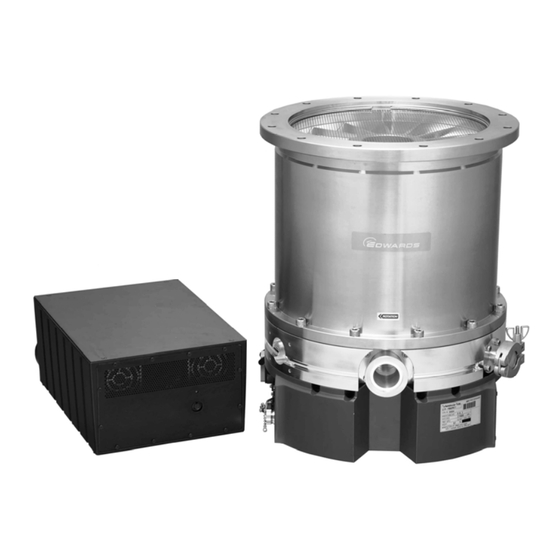
Page 27: External Appearance Of The Stp Pump
STP-iXA2205 Series Turbomolecular Pump External appearance of the STP pump Item Description Inlet Height of water cooling port port VG250 ISO250F ICF305 flange DC cable connector Control unit Height of the purge port Outlet port flange KF40 Screw hole for legs... -
Page 28: External Appearance Of Stp-Ixa2205Cp(V): Vg250/Iso250F/Icf305
STP-iXA2205 Series Turbomolecular Pump Item Description Inlet port VG250 ISO250F ICF305 Height of water cooling port flange DC cable Control unit Height of the purge port Outlet port flange KF40 Fixed screw hole for legs 4-M10 depth 20 Purge port... -
Page 29: External Appearance Of Stp-Ixa2205Cip: Vg250/Iso250F/Icf305
STP-iXA2205 Series Turbomolecular Pump Item Description Inlet port VG250 ISO250F ICF305 Height of water cooling port flange DC cable Control unit Height of the purge port Outlet port flange KF40 Fixed screw hole for legs 4-M10 depth 20 Purge port... -
Page 30: External Appearance Of The Power Unit
STP-iXA2205 Series Turbomolecular Pump External appearance of the power unit 4-M4 depth 6 Figure 12 - External appearance of power unit iPS-1200 Nov. 10 Issue 1-h... -
Page 31: Label Affixing Positions
STP-iXA2205 Series Turbomolecular Pump Label affixing positions Refer to Section 1.6, "Labels" for the details of the labels 1 to 7. (A) Label Affixing positions for the STP pump (B) Label affixing positions for the power unit STP pump installation warning label... - Page 32 STP-iXA2205 Series Turbomolecular Pump This page intentionally blank Nov. 10 Issue 1-h...
-
Page 33: Installation Of The Stp Pump
STP-iXA2205 Series Turbomolecular Pump INSTALLATION OF THE STP PUMP Precautions before installation Installation, operation and maintenance must only be executed by personnel who read through this Manual carefully and have the specific skills to perform installation, operation and maintenance of the STP pump. - Page 34 A place free of exposure to radiation. No discharge of high voltage (more than 500 V) (If more than 500 V is discharged, contact Edwards). Others: An area free of exposure to direct sunlight, high humidity, dust, salty air, dripping water, explosive or flammable gas, corrosive gas, excessive vibration and sources of electric noise.
-
Page 35: Installation Area
STP-iXA2205 Series Turbomolecular Pump 3.1.2 Installation area Leave enough space for the followings in addition to that for the STP pump and power unit: (see Figure 14) •• Space for maintenance and inspection. •• Space for connecting cables. •• Space for ventilation ports for forced air cooling of control unit and power unit. -
Page 36: Bench
The bolt may not be able to be inserted from the lower side of the inlet port according to the shape of the inlet port flange. Note: When the external appearance of the STP pump is not in the manual, contact Edwards. 3.1.4 Insulation test CAUTION The varistor for the power supply line protection is installed in the power unit. -
Page 37: Unpacking
It is recommended to keep the packaging materials, such as the corrugated fiberboard container and cushioning material for possible reuse. If the STP pump is damaged, return it in its original package and contact Edwards or their distributor. WARNING The STP pumps are heavy products. Observe national laws/regulations, safety standards and manufacturers instructions when lifting the STP pump. -
Page 38: Example Of Lifting The Stp Pump (Horizontal Positioning)
STP-iXA2205 Series Turbomolecular Pump When installing the STP pump horizontally using a crane or other appropriate, support pump casing, pump base, or control unit (see Figure 16). DO NOT apply face on convex parts, such as the outlet port or connectors by ropes. Doing so may the pump to fall, or deform and damage the parts. - Page 39 STP-iXA2205 Series Turbomolecular Pump Use lifting devices when instrolling the STP pump under the equipment. A device due to jacking up the STP pump should withstand the load of five times or more the weight of the STP pump. (A) Separate power unit type...
- Page 40 STP-iXA2205 Series Turbomolecular Pump DO NOT the grip and pull the DC cable (Figure 19[A]) and flexible hose (Figure 19[B]) for cooling water when instrolling the STP pump. (A) DC cable (B) Flexible hose for cooling water (STP-iXA2205CP[V]/CIP) (STP-iXA2205CIP) Figure 19 - Prohibited matter Attach the four dedicated legs to place the STP pump in upright position on the floor.
- Page 41 STP-iXA2205 Series Turbomolecular Pump When installing the STP pump to the vacuum equipment in upside-down position, the STP- iXA2205CP(V)/CIP can be loft with the eyebolts attached to the dedicated legs. see Figure 21 A crane and eyebolts due to lifting operations should withstand the load of five times or more the weight of the STP pump, and rope should be seven time or more.
-
Page 42: Name And Function Of Each Part
STP-iXA2205 Series Turbomolecular Pump Name and function of each part 3.3.1 Name and function of the pump The STP pump in Figure 22 is a typical pump model. Refer to Section 2, "TECHNICAL DATA". (A) STP-iXA2205C(V) (A) STP-iXA2205CP(V)/CIP Figure 22 - Configuration of the STP pump... -
Page 43: Name And Function Of The Control Unit
STP-iXA2205 Series Turbomolecular Pump 3.3.2 Name and function of the control unit Figure 23 shows the front panel of the control unit. "DC POWER" connector "POWER" LED "REMOTE" connector "FAILURE" LED "COM1" connector "ROTATION" LED "COM2" connector 10 "Data" LED "STP-LINK"... -
Page 44: Control Unit Front Panel Functions
STP-iXA2205 Series Turbomolecular Pump Item Description Function "DC POWER" connector For power input: 96V DC. (X1: 9 pin) Includes power unit communication signal. "REMOTE" connector For remote input/output signal in the parallel mode setting. (X2: D-Sub37 pin) See Section 4.9, "Parallel port input/output signal". -
Page 45: Name And Function Of The Power Unit
STP-iXA2205 Series Turbomolecular Pump 3.3.3 Name and function of the power unit Figure 24 shows the front panel of the power unit. When performing the insulation test on your equipment, refer to the precautions described in Section 3.1.4, "Insulation test". -
Page 46: Power Unit Front Panel Function
STP-iXA2205 Series Turbomolecular Pump Figure 25 shows the front panel of the power unit. "POWER" LED "STP-LINK" connector Figure 25 - Power unit (front panel) Item Description Function "POWER" LED (Green LED) Lights while the power is ON "STP-LINK" connector... -
Page 47: How To Install The Stp Pump
STP-iXA2205 Series Turbomolecular Pump How to install the STP pump Install the STP pump to the vacuum equipment as shown in Figure 26 and Figure 27. WARNING An appropriate enclosure or a barrier which cannot be removed without using a tool should be provided to prevent an operator from accessing the connection cables between the STP pump and its connectors provided. - Page 48 STP-iXA2205 Series Turbomolecular Pump (Vacuum equipment) Inlet port Inlet port flange Outlet port flange (Vacuum valve) (Backing -pump; dry pump, and other) To power supply AC power cable To vacuum equipment control circuit Remote operation cable The equipment and part within the parentheses must be prepared by the customer.
-
Page 49: Cleaning The Seal
STP-iXA2205 Series Turbomolecular Pump 3.4.1 Cleaning the seal WARNING The wipes used to clean the flange of the pump might become hazardous waste depending upon the solvent (alcohol). Dispose of the contaminated wipes appropriately according to the regulations of each national and/or local government. -
Page 50: Stp Pump Installation Positions
STP-iXA2205 Series Turbomolecular Pump 3.4.2 STP pump installation positions The STP pump can be installed vertically, horizontally, upside-down and/or slanted. Vacuum equipment 4. Slanted Upside-down 5. Vertical Horizontal Figure 28 - STP pump installation positions When installing the STP pump in a horizontal or slanted position, it is recommended to install it so that the direction of the outlet port is on a vertical or horizontal plane in the direction of the gravity. -
Page 51: Secure The Stp Pump
Use a material that has a tensile strength of 600 N/mm or more. When securing the base, use stainless steel securing bolts with a tensile strength class of 70 or more. Note: When using any securing method other than that specified in this manual, contact Edwards. Nov. 10 Issue 1-h... -
Page 52: Maximum Torque Predicted And Recommended Securing Bolt For Inlet Port Flange
STP-iXA2205 Series Turbomolecular Pump Pump model STP-iXA2205C/CV Flange type ISO250F VG250 ICF305 Toque reduction Equipped (optional) Not Equipped (standard) Not Equipped (standard) Not Equipped (standard) mechanism Destructive Torque 36.2 56.3 72.8 72.8 [kNm] Base (4 positions) securing Shape Standard R.D.S.B. - Page 53 STP-iXA2205 Series Turbomolecular Pump The generated destructive torque depends on the presence of a torque reduction mechanism that can be built into the flange, according to the pump model and flange type. This mechanism, shown in Figure 30, is designed to absorb energy and also buffer the destructive torque.
-
Page 54: Shape Of Reduced Diameter Shank Bolts
STP-iXA2205 Series Turbomolecular Pump Vacuum equipment Inlet port flange Washer Torque reduction mechanism Bolt insert position *ISO250F:A=15 (only with torque reduction mechanism) Figure 30 - Shape of reduced diameter shank bolts (ii) When the base is (i) When the base is... -
Page 55: Shape Of Reduced Diameter Shank Bolts
STP-iXA2205 Series Turbomolecular Pump Refer to Figure 32 for the shape of Reduced Diameter Shank Bolts (R.D.S.B.) ISO_F flange VG/ICF flange Vacuum equipment Clearance made by cantering Pump flange Figure 32 - Shape of reduced diameter shank bolts Use Table 9 in conjunction with Figure 32. Ensure that the surface of the levelled and smoothed area (expressed by "D"... -
Page 56: Legs For Securing The Base
STP-iXA2205 Series Turbomolecular Pump 3.4.4 Legs for securing the base CAUTION When securing the base, use stainless steel securing bolts with a tensile strength class is 70 or more. CAUTION When making legs to secure the base, make the length of legs 150 mm or less. Use a material that has a tensile strength of 600 N/mm or more (STP-iXA2205CP[V]/CIP). -
Page 57: Installation Of The Power Unit
STP-iXA2205 Series Turbomolecular Pump Installation of the power unit CAUTION Beware of any obstacles and leave enough space to install the cables without bending them excessively when installing the STP pump. Secure the power unit using the screw holes (4 × M4, depth 6) on the bottom. -
Page 58: External Power Supply Unit
STP-iXA2205 Series Turbomolecular Pump External power supply unit When not using the power unit iPS-1200 (optional accessory), procure the DC power supply unit which satisfies the following specifications at your company for power supply to the STP pump. (contact Service office for detail specification.) Rated output voltage: 96V DC ±... - Page 59 STP-iXA2205 Series Turbomolecular Pump Connector X1 Signal Remarks Outline pin No For +96 VDC power +96 V supply For the ground for DC 0 VA power supply DO NOT connect these 3, 4, 5, 6, 7, 8 pins Frame ground...
-
Page 60: Cable Connection
STP-iXA2205 Series Turbomolecular Pump Cable connection 3.8.1 DC cable Control unit side Power unit side Figure 37 - External appearance of DC cable (STP-iXA2205C[V]) Control unit side Power unit side Figure 38 - External appearance of DC cable (STP-iXA2205CP[V]/CIP) Note: The DC cable is not included with STP-iXA2205C(V). -
Page 61: Power Cable
STP-iXA2205 Series Turbomolecular Pump 3.8.2 Power cable WARNING Ensure that the electrical supply cable is suitably protected against earth (ground) faults and that the earth (ground) and "X11 AC POWER" is correctly connected. CAUTION The power cable is designed specifically for the STP pump. DO NOT use the power cable with other products. - Page 62 STP-iXA2205 Series Turbomolecular Pump Power unit side Power side (Primary) Brown or Black1 M4-bolt (fixing screw) Blue or Black2 Crimp-type terminal (M4) Yellow/Green Cover Clearance min. 1.5 mm Terminal block Use material flammability: UL 94V-0 Use the UL-recognized terminal block satisfying with the following conditions;...
-
Page 63: How To Connect The Cables
Moreover, an accident caused by water leaks or gas leak may occur. CAUTION Use the DC cable and the power cable that Edwards has specified. The use of other cables may result in product damage. CAUTION Confirm the power voltage on the label. - Page 64 STP-iXA2205 Series Turbomolecular Pump CAUTION DO NOT place heavy objects on the cables or bend them excessively. Support each cable so as not to apply direct force to the connectors or terminals. If any problem occurs in cables, connectors or terminals, the STP pump may not function normally. DO NOT apply voltage to each connector pin and DO NOT cause any short-circuiting between pins.
-
Page 65: Precautions Of Vacuum Piping
STP-iXA2205 Series Turbomolecular Pump Precautions of vacuum piping CAUTION DO NOT open the STP pump through the flange to atmospheric air while the STP pump is running. If atmospheric air flows into the STP pump, it may not function normally. -
Page 66: Connecting The Purge Port
STP-iXA2205 Series Turbomolecular Pump Note: Maximum flow for water cooled and TMS unit are applicable under the condition listed in Section 2.3, "Water cooling use condition". 3.10 Connecting the purge port When pumping reactive or corrosive gases, introduce a dry N gas or other gas into the STP pump in order to protect the inside of the STP pump. -
Page 67: Connecting The Water Cooling Pipe
STP-iXA2205 Series Turbomolecular Pump 3.11 Connecting the water cooling pipe CAUTION DO NOT expose the control unit and power unit to water when instrolling or removing the water cooling pipe. Secure the connection pipe to prevent water leakage and use cooling water under the conditions provided in Section 2.3, "Water cooling use condition". -
Page 68: Attaching A Baking Heater
STP-iXA2205 Series Turbomolecular Pump 3.12 Attaching a baking heater WARNING The surfaces of the STP pump and its peripheral equipment will become extremely hot when performing baking. NEVER touch them with bare hands. CAUTION Check the rated voltage of the baking heater before use. The range of the available voltage of the backing heater (optional accessory) is display voltage 10 %. -
Page 69: Installation Of The Tms Unit
STP-iXA2205 Series Turbomolecular Pump 3.13 Installation of the TMS unit WARNING The STP pump operates at high temperatures while the Temperature Management System (TMS) unit is in operation. NEVER touch the STP pump and its peripheral equipment while TMS unit are in operation. Operators can burn hands. -
Page 70: Configuration Of The Tms (Stp-Ixa2205Cpv)
STP-iXA2205 Series Turbomolecular Pump STP pump 5. DC cable TMS heater (Built-in) 6. Power unit Control unit 7. TMS heater cable TMS valve 8. Power cable Figure 45 - Configuration of the TMS (STP-iXA2205CPV) Nov. 10 Issue 1-h... -
Page 71: 3.13.2 Tms Heater
3.13.2 TMS heater The TMS heater heats the base of the STP pump. It’’s fitted with the STP-iXA2205CV and STP- iXA2205CVP at the factory. A fuse is set in the TMS heater cable of the STP-iXA2205 series. 3.13.3 TMS valve The TMS valve controls the cooling water in order to maintain a constant temperature inside the STP pump. -
Page 72: 3.13.6 Connecting The Pump And Tms Valve
STP-iXA2205 Series Turbomolecular Pump 3.13.6 Connecting the pump and TMS valve Connect the pump and TMS valve according to Figure 46. Equipment Equipment STP pump STP pump (A) Two-way valve type (B) Three-way valve type Figure 46 - TMS valve connection Use cooling water which fulfils the conditions in Section 2.3, ““Water cooling use condition””. -
Page 73: Connecting To Semiconductor Equipment
STP-iXA2205 Series Turbomolecular Pump 3.14 Connecting to semiconductor equipment The STP pump is a component system when installing to the semiconductor equipment. Consider the following when designing the semiconductor equipment. 3.14.1 Connecting to power The STP pump or power unit iPS-1200 receives its power from the semiconductor equipment electrical distribution system via a circuit breaker. - Page 74 STP-iXA2205 Series Turbomolecular Pump This page intentionally blank Nov. 10 Issue 1-h...
-
Page 75: Operation
STP-iXA2205 Series Turbomolecular Pump OPERATION Gas pumping, cooling and baking the STP pump Installation, operation and maintenance must only be executed by personnel who read through this Manual carefully and have the specific skills to perform installation, operation and maintenance of the STP pump. -
Page 76: How To Introduce A Purge Gas
STP-iXA2205 Series Turbomolecular Pump 4.1.2 How to introduce a purge gas CAUTION When pumping reactive or corrosive gases, introduce a purge gas to protect the inside of the STP pump. Not to do so may result in product damage. Connect a needle valve or a similar part to the purge port and introduce a dry N gas or other gas to perform a gas purge (see Section 3.10, "Connecting the purge port"). -
Page 77: Baking The Stp Pump
STP-iXA2205 Series Turbomolecular Pump Baking the STP pump WARNING The surfaces of the STP pump and its peripheral equipment will become extremely hot. Never touch them with bare hands. CAUTION The TMS unit and the baking heater cannot be used together at the same time. -
Page 78: Before Starting The Stp Pump
STP-iXA2205 Series Turbomolecular Pump Before starting the STP pump CAUTION NEVER connect or disconnect any cables while the power is ON. NEVER turn the primary power OFF (turn the MAIN POWER "OFF") while the STP pump is in rotation. DO NOT release the inlet port flange or outlet port flange into the atmosphere while the STP pump is rotating. -
Page 79: Powering On
STP-iXA2205 Series Turbomolecular Pump Powering ON Turn "ON" the "MAIN POWER" switch on the power unit. When the power unit is not connected to the control unit with the DC cable, the breaker will trip. If no error is found, the magnetic bearing functions and the rotor levitates (POWER ON state). -
Page 80: Starting/Stopping The Stp Pump
STP-iXA2205 Series Turbomolecular Pump 4.6.2 Starting/stopping the STP pump There are two methods for the starting/stopping operation with the parallel port. Use one of them. 1. Connect input Open the circuit between (19)––(37). Method Starting the pump Stopping the pump 1) Short the circuit between (1)-(21). -
Page 81: Pump Operation Method 1 (Voltage Input)
STP-iXA2205 Series Turbomolecular Pump 2. Connect input Short the circuit between (19)––(37). Method Starting the pump Stopping the pump 1) Supply 12 to 24 VDC to the circuit between Shutoff the circuit between (21)––(1). (21)––(1). 2) Supply 12 to 24 VDC to the circuit between (3)––(1) for 0.3 seconds or more. -
Page 82: How To Start/Stop The Stp Pump
STP-iXA2205 Series Turbomolecular Pump How to start/stop the STP pump 4.7.1 Starting the STP pump after stopping Perform the start operation shown in Section 4.6.2, "Starting/stopping the STP pump". The STP pump can be reaccelerated even while it is stopping. -
Page 83: Led
STP-iXA2205 Series Turbomolecular Pump Three LEDs indicate the pump’’s operational state. Power on state Acceleration Deceleration Warning/ (Levitation state state Failure state state) POWER Steady green Steady green Steady green Steady green (green) (OFF only at power failure) ROTATION Extinguishes... -
Page 84: Parallel Port Input/Output Signal
STP-iXA2205 Series Turbomolecular Pump Parallel port input/output signal The remote input/output signal connector "X2 REMOTE" is used for input/output remote signals (see Figure 52). This connector is of D-Sub (37 pins, socket type) type. The screw for connector is M2.6. -
Page 85: X2 Remote Input Signal Pins
STP-iXA2205 Series Turbomolecular Pump Description Pins for choosing the input signal. (37) (19) When using the contact input, open the circuits between (19)––(37). POLARITY SELECT Pins for inputting the START signal. (21) The following two methods are available: Short the circuits between (1)––(21). Then, short the circuits... -
Page 86: X2 Remote Input Signal Pins (Continued)
STP-iXA2205 Series Turbomolecular Pump Description Pins for inputting the input operation port select signal. When the pins between (1)––(4) are short-circuited, the input operation port will be set to the parallel port automatically, and the input operation via the serial port is disabled. -
Page 87: X2 Remote Input Signal Pins (Contact Input)
STP-iXA2205 Series Turbomolecular Pump A. In case of Start 1) B. In case of Start 2) Figure 53 - X2 REMOTE input signal pins (contact input) Note: COM pins (1, 37 pin) are isolated from the frame ground. Note: The input current of remote input signal is approx. 5 mA. Make sure the minimum applicable load of the relay contact when the remote operation with the relay. -
Page 88: X2 Remote Input Signal Pins (Voltage Input)
STP-iXA2205 Series Turbomolecular Pump Description Pins for choosing the input signal. (37) (19) When using voltage input, short the circuits between (19)––(37). COM POLARITY SELECT (21) Pins for inputting the START signal. The following two methods are available: 1) Supply 12 to 24 VDC to the circuits between (21)––(1). Then, STOP supply 12 to 24 VDC to the circuits between (3)––(1) for 0.3... -
Page 89: X2 Remote Input Signal Pins (Voltage Input) (Continued)
STP-iXA2205 Series Turbomolecular Pump Description Pins for inputting the rotation INHIBIT signal. The input pins are valid even when input operation port is set to serial port. + INHIBIT IN When the pins (5)––(1) are shutoff, the STP pump does not rotate despite the presence of a start signal. -
Page 90: X2 Remote Input Signal Pins (Voltage Input)
STP-iXA2205 Series Turbomolecular Pump A. In case of Start 1) B. In case of Start 2) Figure 54 - X2 REMOTE input signal pins (voltage input) Nov. 10 Issue 1-h... -
Page 91: Input Operation Port Setting
STP-iXA2205 Series Turbomolecular Pump 4.9.2 Input operation port setting Set the input operation port to the parallel port when operating the STP pump via the connector X2. The input operation port can be changed by "PORT SELECT IN" signal of the connector X2 and "Remote Operation Mode"... -
Page 92: Rotation Inhibit Signal
STP-iXA2205 Series Turbomolecular Pump 4.9.3 Rotation INHIBIT signal When using rotation INHIBIT signal, short-circuit the "INHIBIT ENABLE IN" signal. Relations between rotation INHIBIT signal input and pump operation state are shown in Table 23. Signal input Pump operation After short-circuit of rotation INHIBIT input... -
Page 93: Output Signal Pins
STP-iXA2205 Series Turbomolecular Pump 4.9.4 Output signal pins Table 24 and Figure 55. The pins function when the input operation port is either in parallel port setting or serial port setting. Three abbreviations are used in Table 24. N.O OUT: Normal Open Output Pin N.C OUT:... -
Page 94: X2 Remote Output Signal Pins
STP-iXA2205 Series Turbomolecular Pump Description Pins for outputting the POWER ON state signal. (28) POWER These pins are closed when magnetic bearing functions and N.O OUT the rotor levitates. This output is opened at a power failure (10) (29) Pins for outputting the ACCELERATION state signal. -
Page 95: X2 Remote Output Signal Pins
STP-iXA2205 Series Turbomolecular Pump Figure 55 - X2 REMOTE output signal pins Nov. 10 Issue 1-h... - Page 96 STP-iXA2205 Series Turbomolecular Pump Table 25 shows the rated contacts for relays CR1 to CR8 in Figure 55. Resistance Load (COS Ø=1) Rated Load 125 V AC, 0.3 A 30 V DC, 0.5 A Rated Current 0.5 A Maximum Contact Point Current 0.5 A...
-
Page 97: Operating The Tms Unit (For Use With The Tms Unit)
STP-iXA2205 Series Turbomolecular Pump 4.10 Operating the TMS unit (for use with the TMS unit) 4.10.1 Before starting Check the following items before starting: 1. Check that the TMS heater cable is securely connected to the power unit. 2. Check that the TMS valve, the cooling water pipe, and the TMS connection cable are securely connected. - Page 98 STP-iXA2205 Series Turbomolecular Pump This page intentionally blank. Nov. 10 Issue 1-h...
-
Page 99: Serial Communication Protocol
STP-iXA2205 Series Turbomolecular Pump SERIAL COMMUNICATION PROTOCOL Introduction STPiXA2205 series is provided with compliant serial RS232/RS485 interface. Prepare the user application according to this protocol procedure. Operation instructions and information, such as the running state and setting values of the STP pump can be set by the software. -
Page 100: Connection And Setting Up
STP-iXA2205 Series Turbomolecular Pump Connection and setting up 5.2.1 Signal connection 1. Serial Port COM1 (X3 COM1 connector) The serial port COM1 is available for the serial communication via RS232 or RS485. When using a user application, connect it to this port. - Page 101 STP-iXA2205 Series Turbomolecular Pump Figure 57 - X3/X4 connector (D-Sub9) Note: The connectors X3 and X4 are fitted using M2.6 screws. Note: It is recommended to use a communication cable with shield type, and connect both terminals to the ground.
-
Page 102: Connecting The Rs485
Connect the terminator to the communication devises at both ends of the transmission line. The terminator (120 , 0.25 W) is required for connection. (the STP-iXA2205 series dose not have terminator setting function) 7 (D––) (connector X3 8 (D+) -
Page 103: Communication Parameter Setting
STP-iXA2205 Series Turbomolecular Pump Note: It is recommended to use a communication cable (twisted-pair wire) with shield type, and connect both terminals to the ground. 5.2.3 Communication parameter setting The factory setting of COM1 and COM2 is shown in Table 27. To set communication parameters, use the STP-Link (optional accessory) or the display unit iDT-001 (optional accessory). -
Page 104: Input Operation Port Setting
STP-iXA2205 Series Turbomolecular Pump 5.2.4 Input operation port setting Set the input operation port to the serial port when operating the STP pump via the serial port in accordance with the following procedures. 1. Open the "PORT SELECT IN" signal between (1)––(4) of the "X2 REMOTE" connector. -
Page 105: Serial Communication Timeout Setting
STP-iXA2205 Series Turbomolecular Pump 5.2.5 Serial communication timeout setting If the signal to the input operation port of the STP pump is interrupted for a certain period during acceleration or normal operation, the STP pump detects a failure and stops. The time setting of the failure detection is user definable. -
Page 106: Protocol Specifications
STP-iXA2205 Series Turbomolecular Pump Protocol specifications 5.3.1 General description The STP serial communication protocol enables the SIM to receive the communication command transmitted from the PC and sends a response following the communication command (Figure 59-1). Each communication command from the PC transmits a text message (ASCII text) assigned to each function (Figure 59-2). -
Page 107: Standard Transmission Frame
STP-iXA2205 Series Turbomolecular Pump Table 30 shows ASCII characters being used in the transmission control, error control and handshake in the application layer. ASCII Function character code Transmission layer Transmission block start character Transmission frame end character Transmission block end character... -
Page 108: Control Command
STP-iXA2205 Series Turbomolecular Pump Transmission frame when a message exceeds 255 characters (n = 255, m<=255, k = the number of transmission blocks): First 5+n+1 5+n+2 Block ASCII Second 5+n+1 5+n+2 Block ASCII Final 5+m 5+m+1 5+m+2 Block ASCII "Stx" is used as a start character of each transmission block; "Etb" is used as an end character of the transmission block with a message of 255 characters;... -
Page 109: Query Command
STP-iXA2205 Series Turbomolecular Pump Then the preceding SIM->PC character is "Ack", the instructed control command is executed and the SIM returns the following response. PC->SIM Ack or Nak SIM->PC Stx # or ! Etx LRC The PC transmits "Ack" or "Nak"; then transmits the next command if necessary. -
Page 110: Transmission Data Format
STP-iXA2205 Series Turbomolecular Pump Parameter (from C to C ) serves as 16 bits signed hexadecimal value coded ASCII text. When a message (a space character, a function code, and parameter) exceeds 255 characters, input "?" and CHR to the top transmission block only (the first transmission block of the transmission frame). It is not necessary to input them to the 2nd and succeeding transmission blocks. -
Page 111: Frame Control (Checksum)
STP-iXA2205 Series Turbomolecular Pump 5.3.6 Frame control (checksum) The transmission frame is controlled by the odd number parity check. First initialize LRC as FF Next calculate LRC by EXCLUSIVE-OR (XOR) of all the frame bytes containing "Stx", "Etb", "Etx" and LRC and transmit the result as LRC. - Page 112 STP-iXA2205 Series Turbomolecular Pump Examples: Network frame ID character and number in the multi-point connection ASCII Network frame No "1" ASCII Network frame No "100" ASCII Network frame No "127" The transmission frame has a single block or multiple transmission blocks. Each transmission block...
-
Page 113: Control Command In The Rs485 Multi-Point Connection
STP-iXA2205 Series Turbomolecular Pump 5.3.9 Control command in the RS485 multi-point connection The control command to be used when a pump operation instruction or a setting change instruction is transmitted to the SIM and is arranged in the order specified below. The top is "Sp" (space character, HEX code "20") and ASCII characters corresponding to the respective function code and parameter... -
Page 114: 5.3.10 Query Command In The Rs485 Multi-Point Connection
STP-iXA2205 Series Turbomolecular Pump Next, the preceding SIM->PC character is "Ack", the PC continues instructing the control command (the 2nd block). PC->SIM @ F Stx 0 Etx LRC SIM->PC Ack or Nak Always assign less than 510 characters (n< 510) to the parameter so that the message is less than 512 characters. -
Page 115: 5.3.11 Broadcasting Command In The Rs485 Multi-Point Connection
STP-iXA2205 Series Turbomolecular Pump Always assign less than 254 characters (n< 254) to the parameter so that the message is less than 256 characters. Next, the preceding SIM->PC character is "Ack", the instructed query command is executed and the SIM returns the following response (1st block). -
Page 116: Command Specifications
STP-iXA2205 Series Turbomolecular Pump Command specifications 5.4.1 Command list Function Command/Query Name Function code ReadMeas Reads the measured rotational speed. Command Sends commands START, STOP, RESET (These commands are valid only when being sent to the serial port which is set as the input operation port.) -
Page 117: Readmeas
STP-iXA2205 Series Turbomolecular Pump 5.4.2 ReadMeas Function: Reads the measured rotational speed. Transmission frame: PC->SIM Stx Etx LRC SIM->PC PC->SIM SIM->PC Stx D Parameter 1 to 2 Etx LRC Parameter Item Data format Remarks [System reservation] 56-bits hexadecimal coded ASCII... -
Page 118: Readfailmess
STP-iXA2205 Series Turbomolecular Pump Parameter Item Data format Remark Pump operation command 8-bits hexadecimal coded Refer to Table 33 ASCII Pump operation command Value START STOP RESET Table 33 - Pump operation commands Example: Pump operation command : RESET operation = 4 = 04... - Page 119 STP-iXA2205 Series Turbomolecular Pump Parameter Item Data format Remarks The number of error 8-bits hexadecimal Up to 80 errors coded ASCII 2 to 81 Error 1 8-bits hexadecimal coded ASCII …… …… Error 80 8-bits hexadecimal coded ASCII *1 The maximum number of errors may differ depending upon the software version of the STP pump. It is recommended that an application be designed as variable-length data.
- Page 120 STP-iXA2205 Series Turbomolecular Pump Error message Value Error message Value Ram Error AMB Com. Failure [System reservation] [System reservation] TMS Higher Temp TMS Sensor Lost [System reservation] [System reservation] [System reservation] [System reservation] Power Failure [System reservation] Power Supply Fail...
-
Page 121: Error Message Values
STP-iXA2205 Series Turbomolecular Pump Error message Value Error message Value [System reservation] [System reservation] [System reservation] [System reservation] [System reservation] [System reservation] [System reservation] [System reservation] [System reservation] [System reservation] [System reservation] [System reservation] Aberrant Brake [System reservation] Aberrant Accel... -
Page 122: Readmodfonct
STP-iXA2205 Series Turbomolecular Pump 5.4.5 ReadModFonct Function: Reads the pump operation mode and the errors being detected. The data of errors being detected reads the same data as that of "ReadFailMess". Transmission frame: PC->SIM Stx Etx LRC SIM->PC PC->SIM SIM->PC Stx... - Page 123 STP-iXA2205 Series Turbomolecular Pump Pump operation mode Value Levitation No Levitation Acceleration Normal Deceleration (Brake) Autotest Tuning Tuning Complete [System Reservation] 9, 10, 11 Table 36 - Pump operation mode Example: Pump operation mode : 01 = 1 = Levitation...
-
Page 124: Readversion
STP-iXA2205 Series Turbomolecular Pump 5.4.6 ReadVersion Function: Read the software version. Transmission frame: PC->SIM Stx Etx LRC SIM->PC PC->SIM SIM->PC Stx Parameter 1 to 24 Etx LRC Parameter Item Data format Remarks 1 to 16 Control unit software version 8-bits hexadecimal... -
Page 125: Readcounters
STP-iXA2205 Series Turbomolecular Pump 5.4.7 ReadCounters Function: Reads serial number, hour counter and start counter. Transmission frame: PC->SIM Stx Etx LRC SIM->PC PC->SIM SIM->PC Stx Parameter 1 to 23 Etx LRC Parameter Item Data format Remarks 1 to 10 Control unit serial number... -
Page 126: Readsetpoint
STP-iXA2205 Series Turbomolecular Pump 5.4.8 ReadSetPoint Function: Reads the setting value of the "Speed Set Point" and TMS temperature. The "Speed Set Point" data is the same data as that of "ReadSpeedSetPoint". Transmission frame: PC->SIM Stx Etx LRC SIM->PC PC->SIM SIM->PC Stx... -
Page 127: 5.4.10 Readstatus
STP-iXA2205 Series Turbomolecular Pump Parameter Item Data format Remark Motor temperature 16-bits hexadecimal (Unit: ºC) coded ASCII Example: Motor temperature : 0014 = 20 ºC (68 ºF) Parameter ASCII 30 30 31 34 5.4.10 ReadStatus Function: Reads various settings (Remote mode, TMS function, Emergency vent valve). -
Page 128: 5.4.11 Readevents
STP-iXA2205 Series Turbomolecular Pump Remote mode Value I/O Remote (X2) COM1 (X3) COM2 (X4) COM3 (X5 STP-Link) COM4 (X14 power unit) [System reservation] 3, 4 Table 37 - Remote mode Example: Remote mode setting : 01 = I/O Remote TMS function setting... -
Page 129: 5.4.12 Setspeedsetpoint
STP-iXA2205 Series Turbomolecular Pump Parameter Item Data format Remarks The number of 8-bits hexadecimal Up to 10 errors "Error Record" coded ASCII 2 to 11 Error Record 1 to 8-bits hexadecimal Error Record 10 coded ASCII *1 Value corresponding to the error message is transmitted (refer to Table 34 and Table 35). The most recent error has the smallest parameter number. -
Page 130: 5.4.13 Readspeedsetpoint
STP-iXA2205 Series Turbomolecular Pump Parameter Items Data format Remark Speed Set Point 16-bits hexadecimal (Unit: Hz) coded ASCII *1 When the value set to the parameter is larger than the upper limit, it is automatically set to the upper limit. When the value set to the parameter is smaller than the lower limit, it is automatically set to the lower limit. -
Page 131: 5.4.14 Readmodfonctwithwarning
STP-iXA2205 Series Turbomolecular Pump 5.4.14 ReadModFonctWithWarning Function: Reads the pump operation mode, errors and warnings being detected. The data of errors being detected data is the same data as that of "ReadFailMess". Transmission Frame: PC SIM Stx Etx LRC SIM PC... - Page 132 STP-iXA2205 Series Turbomolecular Pump Warning message 16-bits hex value 0001 [System reservation] WARNING: Second Damage Limit 0002 WARNING: First Damage Limit 0004 WARNING: Imbalance X_H 0008 WARNING: Imbalance X_B 0010 WARNING: Imbalance Z 0020 WARNING: Pump Run Time Over 0040...
- Page 133 STP-iXA2205 Series Turbomolecular Pump Example: Pump operation mode : 01 = 1 = Levitation WARNING being detected : 000C = 0004 OR 0080 "WARNING: First Damage Limit" and "WARNING: Imbalance X_H" The number of error : 02 = 2 errors...
-
Page 134: 5.4.15 Readmeasvalue
STP-iXA2205 Series Turbomolecular Pump 5.4.15 ReadMeasValue Function: Reads the TMS temperature, motor temperature, motor current, measured rotational speed, and control unit temperature. The motor temperature value is the same temperature as "ReadMotorTemp". The measured rotational speed value is the same as "ReadMeas" parameter 2 (Measured rotational speed). - Page 135 STP-iXA2205 Series Turbomolecular Pump Example: TMS temperature: 0046 = 70 ºC (158ºF) Motor temperature: 0014C = 20 ºC (68ºF) Motor current: = 2.5A Measured rotational speed: 01C2 = 450 Hz = 27,000 rpm Control unit temperature : 0032 = 50 °C...
-
Page 136: 5.4.16 Readoptionfunc
STP-iXA2205 Series Turbomolecular Pump 5.4.16 ReadOptionFunc Function: Reads the setting value of the input operation port, warning function, and serial communication time out. Transmission frame: PC SIM Stx Etx LRC SIM PC PC SIM SIM PC Stx Parameter 1 to 13 Etx LRC *1 The HEX code of ASCII character ' = ' is "3D". - Page 137 STP-iXA2205 Series Turbomolecular Pump Parameter Item Data format Remarks Serial communication time out 16-bits hexadecimal 60 sec. step setting (Unit: sec.) coded ASCII [System reservation] 88-bits hexadecimal coded ASCII Parameter Item Setting range I/O REMOTE (X2): Input operation port setting...
- Page 138 STP-iXA2205 Series Turbomolecular Pump Example: Input operation port: = I/O REMOTE TMS Option: = DISABLE Second Damage Limit Option: = ENABLE First Damage Limit Warning: = ENABLE Pump Runtime Over Warning: = DISABLE Pump Runtime Over Warning hours: 000003E8 = 1,000 (×100 hours)
-
Page 139: 5.4.17 Setoptionfunc
STP-iXA2205 Series Turbomolecular Pump 5.4.17 SetOptionFunc Function: Changes the setting value of the input operation port, warning function, and serial communication time out. Transmission frame: PC->SIM Stx Parameter 1 to 13 Etx LRC SIM->PC PC->SIM SIM->PC Stx Etx LRC *1 The HEX code of ASCII character ' = ' is "3D". - Page 140 STP-iXA2205 Series Turbomolecular Pump Parameter Item Data format Remarks [System reservation] 88-bits hexadecimal coded ASCII the parameter value Fhex or the reading data of ReadOptionFunc (?=). *1 Assign Refer to Table 39, "Parameter setting value" for each parameter setting value.
-
Page 141: 5.4.18 Readcondition
STP-iXA2205 Series Turbomolecular Pump 5.4.18 ReadCondition Function: Reads the pump model and damage point. Transmission frame: PC SIM Stx Etx LRC SIM PC PC SIM SIM PC Stx Parameter 1 to 4 Etx LRC *1 The HEX code of ASCII character ' { ' is "7B". - Page 142 STP-iXA2205 Series Turbomolecular Pump Example: Pump model: 5354502D6958413232303520202020202020202020 = STP iXA2205 Damage point: = 50 Parameter "S" "T" "P" "––" "i" "X" "A" "2" "2" "0" ASCII 35 33 35 34 35 30 32 44 36 39 35 38 34 31 33 32 33 32 33 30 Parameter "5"...
-
Page 143: 5.4.19 Readeventswithtime
STP-iXA2205 Series Turbomolecular Pump 5.4.19 ReadEventsWithTime Function: Reads the "Error Record" with detection time. Transmission frame: PC SIM Stx Etx LRC SIM PC PC SIM SIM PC Stx Parameter 1 to 15 Etx LRC PC SIM SIM PC Stx Parameter 15 to 22 Etx LRC *1 The HEX code of ASCII character ' } ' is "7D". - Page 144 STP-iXA2205 Series Turbomolecular Pump 1. In case of time flag = 0 Parameter Item Data format Remarks Error Code 8-bits hexadecimal coded ASCII Time flag 8-bits hexadecimal coded ASCII Pump running time 32-bits hexadecimal Unit: minute coded ASCII Control unit running time...
- Page 145 STP-iXA2205 Series Turbomolecular Pump Example: In case of Disturbance X_H detection at September 13, 2007 12: 34 Parameter ASCII 30 44 30 31 30 37 30 39 31 33 31 32 33 34 *3 System reservation Example: When 3 errors have been detected in the past;...
- Page 146 STP-iXA2205 Series Turbomolecular Pump Parameter ASCII 46 46 30 30 30 30 30 30 30 30 30 30 30 30 Parameter ASCII 46 46 30 30 30 30 Parameter ASCII 46 46 30 30 30 30 30 30 30 30 30 30 30 30 *1 System reservation Nov.
-
Page 147: Stp-Link And Display Unit
STP-iXA2205 Series Turbomolecular Pump STP-LINK and DISPLAY UNIT The STP-Link (optional accessory) and the display unit iDT-001 (optional accessory) are available with the STP pump. STP-Link The "STP-Link" is a Windows application for operating the STP pump, confirming the pump status or setting various settings. -
Page 148: Display Unit
STP-iXA2205 Series Turbomolecular Pump Display unit The "display unit" operates the STP pump, confirms the pump status or sets various settings. The display unit iDT-001 is equipped with an LCD and flat panel switches. See the Instruction Manual of the "Display unit iDT-001" for the detailed specification and operating methods. -
Page 149: Safety Functions
STP-iXA2205 Series Turbomolecular Pump SAFETY FUNCTIONS The STP pump is provided with safety functions for various abnormalities/errors. When two or more warnings are detected simultaneously, a high-priority warning is indicated. Also, the warning signal is output from the "X2 REMOTE" connector. If an abnormality/error is found when using the STP pump, check it and take measures in accordance with the following procedures. -
Page 150: Operation After A Power Recovery
STP-iXA2205 Series Turbomolecular Pump Table 41 shows the states of LED output and the "X2 REMOTE" output signals at a power failure. REMOTE output signal LEDs (REMOTE X2) Rotational Duration of speed power failure ALARM POWER FAILURE POWER N.O. N.C. -
Page 151: Abnormal State Of Magnetic Bearing (Disturbance)
STP-iXA2205 Series Turbomolecular Pump 7.1.3 Abnormal state of magnetic bearing (Disturbance) CAUTION When an abnormality/error occurs in the magnetic bearing, check the STP pump. If "FAILURE" cannot be released after reset operation, contact Service office. When the magnetic bearing does not function normally due to a breakage of the STP connection cable, disconnection of connectors or any abnormality/error of the STP control circuit, the rotor lands on the touch down bearing and stops. -
Page 152: Overspeed
STP-iXA2205 Series Turbomolecular Pump 7.1.8 Overspeed When the rotational speed of the STP pump exceeds 29,000 rpm due to a failure in the motor driver, the STP pump decelerates and stops. The "FAILURE" LED (red) illuminates, and a failure signal is output from the "X2 REMOTE"... -
Page 153: Warning" Function
STP-iXA2205 Series Turbomolecular Pump "WARNING" function 7.2.1 "WARNING" function The STP pump is provided with a WARNING function when an overhaul is needed following a self-test as shown in Table 42. The type of warning is indicated by flashing pattern of the "FAILURE" LED (orange). -
Page 154: Warning Output
STP-iXA2205 Series Turbomolecular Pump Warning detection "FAILURE" LED indication First Damage Limit Second Damage Limit (3 flashes in orange) Pump Run Time Over Pump Overload Corresponding to (2 flashes in orange) warning type Imbalance (1 flash in orange) 1 cycle X2 REMOTE output WARNING N.O OUT... -
Page 155: Contents Of Warning Function
STP-iXA2205 Series Turbomolecular Pump Contents of WARNING function 7.3.1 First Damage limit Impact of the STP pump rotor onto the touch-down bearing, such as by an unexpected in-rush of air from outside or in the event of power failure, can damage the touch-down bearings. The STP pump monitors these impacts and assigns damage points to the event of "Disturbance"... -
Page 156: Pump Overload
STP-iXA2205 Series Turbomolecular Pump 7.3.4 Pump Overload "Pump Overload" is displayed when the state that the motor current exceeding the setting value continues during the fixed time or the state that the STP pump rotational speed drops below the setting value continues during the fixed time. However, the motor current and the rotational speed are monitored only in the NORMAL state. -
Page 157: Warning Function Setting
STP-iXA2205 Series Turbomolecular Pump WARNING function setting The WARNING functions can be set to Enable or Disable. Set to "ENABLE" when using the WARNING function. Set to "DISABLE" to release each WARNING function after the WARNING is detected. A setting value of the "Pump Run Time Over" and "Pump Overload" are adjustable. The WARNING detection can be released by setting the value larger than pump running hours after "Pump Run Time... -
Page 158: Troubleshooting Immediately After Failure Occurs
STP-iXA2205 Series Turbomolecular Pump Troubleshooting immediately after failure occurs The STP pump is provided with safety functions for various abnormities/errors. A safety function operates when an abnormality/error occurs. The "FAILURE" LED illuminates or flashes. Also, the failure signal is output from the "X2 REMOTE" connector. If an abnormality/error is found when using the STP pump, check it and take measures in accordance with the following procedures. -
Page 159: Troubleshooting
STP-iXA2205 Series Turbomolecular Pump Troubleshooting 7.6.1 Indication of "FAILURE" LED (red) The flashing pattern of the "FAILURE" LED (red) differs depending on the type of abnormality/error. When two or more failures are detected simultaneously, a high-priority failure is indicated. Also, the failure signal is output from the "X2 REMOTE"... - Page 160 STP-iXA2205 Series Turbomolecular Pump Nov. 10 Issue 1-h...
- Page 161 STP-iXA2205 Series Turbomolecular Pump Nov. 10 Issue 1-h...
- Page 162 STP-iXA2205 Series Turbomolecular Pump Nov. 10 Issue 1-h...
- Page 163 STP-iXA2205 Series Turbomolecular Pump Nov. 10 Issue 1-h...
- Page 164 STP-iXA2205 Series Turbomolecular Pump Nov. 10 Issue 1-h...
- Page 165 STP-iXA2205 Series Turbomolecular Pump Nov. 10 Issue 1-h...
-
Page 166: Indication Of "Failure" Led (Green)
STP-iXA2205 Series Turbomolecular Pump 7.6.2 Indication of "FAILURE" LED (green) If an abnormality/error is detected by self test during the power ON operation, "FAILURE" LED flashes green. This is the indication of STP pump or control unit failure. Contact Service Office. -
Page 167: Maintenance And Inspection
NEVER open any panel because it could cause shock, malfunction, or short circuit. Power OFF the peripheral equipments before performing maintenance and inspections. Only Edwards will replace the maintenance parts, and will execute repair and overhaul. Contact Service office. -
Page 168: Cleaning
Contact with the atmosphere may cause a reaction of the deposit. DO NOT open the STP pump to the atmosphere. Edwards can supply a Temperature Management System (TMS) unit which will keep the temperature high inside the STP pump and prevent the accumulation of deposit. For details, contact Edwards. Nov. 10 Issue 1-h... -
Page 169: Overhaul
STP-iXA2205 Series Turbomolecular Pump Overhaul Deterioration or abrasion of the internal parts of the STP pump will cause a failure. The recommended maintenance intervals for different process applications are tabulated below: Process Period Remarks Metal Etch Process 1 year Processes resulting in large amount of deposits in (deposition) the pump will require more frequent service. -
Page 170: Transporting For Repair Or Overhaul
Procedure". CAUTION When returning the STP pump to Edwards, be sure to pack it well to prevent external damage. If the "Return Procedure" has not been satisfied, Edwards will not be responsible for any troubles. Always contact Service office before returning the STP pump for repairs, overhaul, or other purposes. - Page 171 STP-iXA2205 Series Turbomolecular Pump Back side (A) Control unit STP-iXA2205C(V) Front side Back side (B) Control unit and power unit STP-iXA2205CP(V) Figure 63 - Method for sealing ventilation port Nov. 10 Issue 1-h...
- Page 172 STP-iXA2205 Series Turbomolecular Pump This page intentionally blank. Nov. 10 Issue 1-h...
-
Page 173: Storage And Disposal
STP-iXA2205 Series Turbomolecular Pump STORAGE AND DISPOSAL Storage of the STP pump When planning not to use the STP pump over a long period (more than a few months), follow the precautions below: 1. Store the STP pump in a vertical position. Attach the dedicated legs for standing to the STP- iXA2205CP(V)/CIP series pumps. -
Page 174: Disposal
Material Safety Data Sheet (MSDS) you obtain from the gas supplier. Dispose of the STP pump as industrial waste in accordance with all local and national safety and environmental standards. Note: Edwards will not be responsible for problems during or after disposal. Nov. 10 Issue 1-h... -
Page 175: Service, Spares And Accessories
A majority of these centres employ Service Engineers who have undergone comprehensive Edwards training courses. Order spare parts and accessories from your nearest Edwards company or distributor. When you order, state for each part required:... -
Page 176: Accessories
STP-iXA2205 Series Turbomolecular Pump 10.4 Accessories The following is a list of accessories that can be purchased by contacting Edwards. Items Application purpose Remarks Instruction Manual STP Pump Instruction Manual This manual Supplied with STP pump Power cable Primary input power Standard cable length is 5 m. - Page 177 For more information, contact the nearest Service Office. Manufacturer: Edwards Japan Limited 1078-1, Yoshihashi, Yachiyo-shi, Chiba 276-8523 JAPAN Telephone: Domestic 047-458-8822 International +81-47-458-8822 Facsimile: Domestic 047-458-8833 International +81-47-458-8833 Copyright 2010 Edwards Japan Limited. All rights reserved.
Need help?
Do you have a question about the STP-iXA2205 Series and is the answer not in the manual?
Questions and answers