Graco Reactor E-20 Series Manual
Electric, heated, plural component proportioner
Hide thumbs
Also See for Reactor E-20 Series:
- Operation manual (42 pages) ,
- Electrical diagrams (12 pages) ,
- Repair parts (72 pages)
Table of Contents
Advertisement
Repair - Parts
Electric, Heated, Plural Component Proportioner. For spraying polyurethane foam and
polyurea coatings. For professional use only.
Not approved for use in European explosive atmosphere locations.
Important Safety Instructions
Read all warnings and instructions in this
manual. Save these instructions.
See pages 3 and 4 for model information, including
maximum working pressure and approvals.
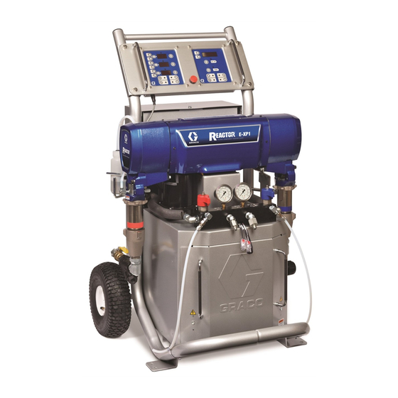
Model E-XP1 Shown
312066ZAD
EN
Advertisement
Table of Contents

Related Manuals for Graco Reactor E-20 Series


Summary of Contents for Graco Reactor E-20 Series
- Page 1 Repair - Parts 312066ZAD Electric, Heated, Plural Component Proportioner. For spraying polyurethane foam and polyurea coatings. For professional use only. Not approved for use in European explosive atmosphere locations. Important Safety Instructions Read all warnings and instructions in this manual. Save these instructions. See pages 3 and 4 for model information, including Model E-XP1 Shown maximum working pressure and approvals.
-
Page 2: Table Of Contents
Troubleshooting ......20 Graco Information ......76 Reactor Electronics . -
Page 3: Models
Models Models E-20 SERIES Max Flow Approximate Primary Rate◆ Output per Cycle Maximum Fluid Full Load Peak Voltage System Heater lb/min (A+B) Working Pressure Part, Series Amps* (phase) Watts† Watts (kg/min) gal. (liter) psi (MPa, bar) 259025, F 230V (1) 10,200 6,000 20 (9) -
Page 4: Supplied Manuals
Order Part 15M334 for a compact disk of Reactor manu- Order Part 15M334 for a compact disk of Reactor manu- als translated in several languages. als translated in several languages. Reactor Data Reporting Kit Manuals are also available at www.graco.com. Part Description 309867 Instruction-Parts Manual (English) -
Page 5: Warnings
Warnings Warnings The following warnings are for the setup, use, grounding, maintenance, and repair of this equipment. The exclama- tion point symbol alerts you to a general warning and the hazard symbol refers to procedure-specific risk. Refer back to these warnings. Additional, product-specific warnings may be found throughout the body of this manual where applicable. - Page 6 • Ground equipment, personnel, object being sprayed, and conductive objects in work area. See Grounding instructions. • Use only Graco grounded hoses. • Check gun resistance daily. • If there is static sparking or you feel a shock, stop operation immediately. Do not use equip- ment until you identify and correct the problem.
- Page 7 Warnings WARNING MOVING PARTS HAZARD Moving parts can pinch or amputate fingers and other body parts. • Keep clear of moving parts. • Do not operate equipment with protective guards or covers removed. • Pressurized equipment can start without warning. Before checking, moving, or servicing equipment, follow the Pressure Relief Procedure in this manual.
-
Page 8: Important Two-Component Material Information
Important Two-Component Material Information Important Two-Component Material Information Isocyanate Conditions Spraying or dispensing fluids that contain isocyanates creates potentially harmful mists, vapors, and atomized particulates. • Read and understand the fluid manufacturer’s warnings and Safety Data Sheet (SDS) to know specific haz- ards and precautions related to isocyanates. -
Page 9: For All Applications Except Spray Foam
Important Two-Component Material Information For all applications except spray Keep Components A and B foam Separate Cross-contamination can result in cured material in fluid Spraying or dispensing fluids that contain isocyanates cre- lines which could cause serious injury or damage equip- ates potentially harmful mists, vapors, and atomized partic- ment. -
Page 10: Foam Resins With 245 Fa Blowing Agents
Important Two-Component Material Information Foam Resins with 245 fa Blowing Agents Some foam blowing agents will froth at temperatures above 90°F (33°C) when not under pressure, especially if agitated. To reduce frothing, minimize preheating in a circulation system. Changing Materials NOTICE Changing the material types used in your equipment requires special attention to avoid equipment damage... -
Page 11: Temperature Control Diagnostic Codes
Temperature Control Diagnostic Codes Temperature Control Diagnostic Codes Temperature control diagnostic codes appear on tem- Code Code Name Alarm Corrective perature display. Zone Action page High fluid temperature Individual These alarms turn off heat. E99 clears automatically when communication is regained. Codes E03 through High zone current Individual No zone current with... -
Page 12: E02: High Zone Current
Temperature Control Diagnostic Codes 4. Remove connector B from temperature control mod- E02: High zone current ule, and check continuity of overtemperature switches A and B, thermocouples A and B, or FTS by measuring resistance across the pins on the plug 1. -
Page 13: E03: No Zone Current
Temperature Control Diagnostic Codes E03: No zone current 5. To verify heater control module is not causing the problem, use a wire to short-circuit the two pins cor- 1. Check for tripped circuit breaker inside electrical responding to the FTS (red and yellow for A or B cabinet or at power source for that zone. -
Page 14: Motor Control Diagnostic Codes
Motor Control Diagnostic Codes Motor Control Diagnostic Codes Motor control diagnostic codes E21 through E29 appear Warnings on pressure display. There are two types of motor control codes: alarms and Reactor will continue to run. Press to clear. A warnings. Alarms take priority over warnings. warning will not recur for a predetermined amount of time (varies for different warnings), or until main power Alarms... -
Page 15: E21: No Component A Transducer
Motor Control Diagnostic Codes E21: No component A b. Turn on the Reactor master power. transducer • If the error is gone, turn off the Reactor main power, remove test transducer, and replace “A” 1. Check transducer A connection at J3 on motor con- transducer. - Page 16 Motor Control Diagnostic Codes Checks for Fast E24 Errors 1. Swap the transducer plug-ins on the motor control board. (J3 and J8 for the E-20 and E-XP1. J3 and J5 for the E30 and E-XP1). If a fast E24 error occurs, first check the readings of the analog gauges.
-
Page 17: E25: High Line Voltage
Motor Control Diagnostic Codes E25: High line voltage E28: High current in motor Supply voltage too high. Check Reactor voltage require- Check motor control board: ments, page 75. 1. Turn the master power off. E26: Low line voltage 2. Disconnect socket J4 (E-20/E-XP1) J1 (E-30/E-XP2) on the motor control board. -
Page 18: E31: Motor Control Failure (E-30 And E-Xp2 Only)
Motor Control Diagnostic Codes 3. Check wiring. The orange brush sensor wire coming out of the brush may be routed online with the com- 1. Turn main power OFF . Disconnect power mutator wiring (thick red wire), causing a false alarm. -
Page 19: E32: Motor Control Overtemperature
Communication Diagnostic Codes E32: Motor Control 1. Relieve pressure, page 26. Verify low pressure with analog gauges. Overtemperature The E32 error code indicates a high temperature condi- 2. Turn main power OFF then ON tion within the motor control board (701). This could be caused by an abnormally high ambient temperature in the work location, blockage of cooling vents in the cabi- If error still remains, identify cause of the overtempera-... -
Page 20: Troubleshooting
Troubleshooting Troubleshooting PROBLEM CAUSE SOLUTION Reactor does not operate. No power. Plug in power cord. Turn main power ON Turn circuit breakers ON, page 35. Red stop button circuit open. Check button connections. See page 49 and electrical diagrams. Motor does not operate. Loose connections. -
Page 21: Reactor Electronics
Troubleshooting Reactor Electronics 2. Turn main power OFF 3. Allow equipment to cool. Try the recommended solutions in the order given for each problem, to avoid unnecessary repairs. Also, determine that all circuit breakers, switches, and con- Before performing any troubleshooting procedures: trols are properly set and wiring is correct before assum- ing there is a problem. - Page 22 Troubleshooting PROBLEM CAUSE SOLUTION Poor display connection. Check cable connections, page 49. Replace damaged cable. Display cable damaged or corroded. Clean connections; replace cable if is Display does not respond properly to damaged. button pushes. Ribbon cable on display circuit board Connect cable (page 49) or replace.
-
Page 23: Primary Heaters (A And B)
Troubleshooting Primary Heaters (A and B) 2. Turn main power OFF 3. Allow equipment to cool. Try the recommended solutions in the order given for each problem, to avoid unnecessary repairs. Also, determine that all circuit breakers, switches, and con- Before performing any troubleshooting procedures: trols are properly set and wiring is correct before assum- ing there is a problem. -
Page 24: Hose Heat System
Troubleshooting Hose Heat System 3. Allow equipment to cool. Problems Try the recommended solutions in the order given for each problem, to avoid unnecessary repairs. Also, determine that all circuit breakers, switches, and con- trols are properly set and wiring is correct before assum- Before performing any troubleshooting procedures: ing there is a problem. - Page 25 Troubleshooting PROBLEM CAUSE SOLUTION Faulty thermocouple connections. Verify that all FTS connections are snug and that pins of connectors are clean. Examine connection of thermocouples to long green plug on heater control board. Unplug and re-plug thermocouple wires, cleaning off any debris. Unplug and Erratic hose temperature.
-
Page 26: Repair
Repair Repair 2. Engage gun piston safety lock. Repairing this equipment requires access to parts ti2409a that may cause electric shock or other serious injury if work is not performed properly. Have a qualified elec- 3. Close gun fluid manifold valves A and B. trician connect power and ground to main power switch terminals, see operation manual. -
Page 27: Flushing
Repair Flushing See manual 309577 for pump repair instructions. 1. Shut off , and heat zones. Flush equipment only in a well-ventilated area. Do not spray flammable fluids. Do not turn on heaters while 2. Flush pump. flushing with flammable solvents. 3. - Page 28 Repair Use drop cloth or rags to protect Reactor and sur- Steps 10 and 11 apply to pump B. rounding areas from spills. 10. Disconnect fluid inlet (C) and outlet (D). Also discon- Steps 7-9 apply to pump A. To disconnect pump B, nect steel outlet tube from heater inlet.
-
Page 29: Pump Installation
Repair Pump Installation 2. Continue screwing pump into housing until fluid out- let (D) is aligned with steel tube and top threads are +/- 1/16 in. (2 mm) of bearing face (N). Steps 1-5 supply to pump B. To reconnect pump A, 3. - Page 30 Repair that barbed fittings at wet-cup flush ports are acces- sible. Steps 6-12 apply to pump A only. 9. Connect component A outlet tube loosely at pump and at heater. Line up tube, then tighten fittings 6. Ensure star-shaped locknut (G) is screwed on pump securely.
-
Page 31: Drive Housing
Repair Drive Housing Removal Installation 1. Apply grease liberally to washers (207, 208, 218), all gears, and inside drive housing (202). 1. Turn main power OFF . Disconnect power 2. Install one bronze washer (208) in drive housing, supply. then install steel washers (207, 218) as shown. 2. - Page 32 Repair 206B 206A Crankshaft must be in line with crankshaft at other end of motor. TI3152 312066ZAD...
-
Page 33: Motor Brushes
Repair Motor Brushes 5. Loosen terminal screw (R). Pull away brush lead (L), being careful motor lead terminal (T) remains in place. Remove and discard brush (B). Brush Removal Replace brushes worn to less than 1/2 in. (13 mm). Brushes wear differently on each side of motor;... - Page 34 Repair Brush Installation 4. Install spring clip (C) and push in until hooks (H) catch slots in housing. Incorrect installation may jam clip. CAUTION When installing brushes, follow steps carefully. Improper installation damages parts beyond use. Install brush with wires on same side of motor as before.
-
Page 35: Capacitor Test
Repair Capacitor Test Circuit Breaker Module 1. Turn main power OFF . Disconnect power 1. Turn main power OFF . Disconnect power supply. supply. Turn circuit breakers on to test. 2. Relieve pressure, page 26. 3. Locate the large, blue capacitor in the upper right corner of the lower cabinet. -
Page 36: Electric Motor
Repair Electric Motor Installation 1. Place motor on unit. Thread motor cables into cabi- net and into bundles as before. See electrical dia- Removal grams. 2. Fasten motor with screws. 1. Turn main power OFF . Disconnect power 3. Plug 3-pin connector J7 to board. supply. -
Page 37: Motor Control Board
Repair Motor Control Board 8. Set DIP switch (SW2) on new board. See T ABLE for factory settings. See F . 2 for location on board. Motor control board has one red LED (D11). Power must be on to check. See F . - Page 38 Repair 24G879 Motor Control, for E-20 and E-XP1 DIP Switch (SW2) Settings Model E-20 ON (UP) J3 (A) J8 (B) TI3178b-3 Model E-XP1 ON (UP) TI3178b-4 TI3153A-1 24G881 Motor Control, for E-30 and E-XP2 DIP Switch (SW2) Settings Model E-30 J5 (A) ON (Down) TI3178b-2...
-
Page 39: Transducers
Repair Transducers diagnostic code follows; see E21: No component A transducer, page 15. 5. If transducer fails test, thread cable through top of 1. Turn main power OFF . Disconnect power cabinet. Note path as cable must be replaced in same way. -
Page 40: Temperature Control Module
Repair Temperature Control Module Table 5: Temperature Control Module Connections Connector Description DATA (A) Data reporting HOSE T/C P; FTS (purple) HOSE T/C R; FTS (red) HOSE T/C S; FTS (silver (unshielded bare wire)) HEATER T/C B, Y; Thermocouple (yellow) SENSOR (B) HEATER T/C B, R;... - Page 41 Repair Test SCR Circuit Replacing Temperature Control Assembly Modules 1. Test the SCR circuit in the on position: CAUTION a. Make sure everything is connected, including Before handling assembly, put on a static conductive the hose. wrist strap to protect against static discharge which can damage assembly.
-
Page 42: Primary Heaters
Repair Primary Heaters Line Voltage The primary heaters output their rated wattage at 230 Vac. Low line voltage will reduce power available and Heater Element the heaters will not perform at full capability. 1. Turn main power OFF . Disconnect power supply. - Page 43 Repair r_247813_312066 Apply 110009 thermal heatsink compound. . 6. Heater (7.5 kW Single Zone Heater Shown) 312066ZAD...
- Page 44 Repair adapter must be removed, ensure that mixer (309) Thermocouple is out of the way when replacing the adapter. 8. Replace thermocouple, F . 7. 1. Turn main power OFF . Disconnect power a. Remove protective tape from thermocouple tip supply.
-
Page 45: Heated Hose
Repair Overtemperature Switch For proportioners with a termination box (TB), fol- low steps 3 - 5. For proportioners with electrical 1. Turn main power OFF . Disconnect power splice connectors (12), follow steps 6 - 8. supply. 3. Disconnect power wire harness from terminal block 2. - Page 46 Repair Check FTS Cables 1. Turn main power OFF . Disconnect power supply. 2. Relieve pressure, page 26. 3. Disconnect FTS cable (F) at Reactor, F . 8. TI10964a . 8. Heated Hose 4. Test with ohmmeter between pins of cable connec- tor.
-
Page 47: Fluid Temperature Sensor (Fts)
Repair Fluid Temperature Sensor (FTS) 4. If FTS fails any test, replace FTS. 5. Disconnect air hoses (C, L), and electrical connec- Test/Removal tors (D). 6. Disconnect FTS from whip hose (W) and fluid hoses 1. Turn main power OFF . - Page 48 Repair Transformer Primary Check 3. To verify transformer voltage, turn on hose zone. Measure voltage from 18CB-2 to POD-HOSE-P15-2; see Reactor Electrical Dia- grams manual 312067. 1. Turn main power OFF Model Secondary Voltage 2. Locate the two smaller (10 AWG) wires coming out of transformer.
-
Page 49: Display Module
Repair Display Module Red Stop Button CAUTION Temperature and Pressure Displays Before handling board, put on a static conductive wrist strap to protect against static discharge which CAUTION can damage board. Follow instructions provided with Before handling board, put on a static conductive wrist strap. - Page 50 Repair Apply medium strength thread sealant. ti2574a Detail of Membrane Switches and Display Boards Temperature Display Pressure Display 502c 502a 502b 501c 501a 501b ti3172a . 11. Display Module 312066ZAD...
-
Page 51: Inlet Fluid Strainer Screen
Repair Inlet Fluid Strainer Screen 4. Ensure the pipe plug (D) is securely screwed into the strainer plug (C). Install the strainer plug with the screen (A) and gasket (B) in place and tighten. Do not overtighten. Let the gasket make the seal. 5. -
Page 52: Pump Lubrication System
Repair Pump Lubrication System Check the condition of the ISO pump lubricant daily. Change the lubricant if it becomes a gel, its color dark- ens, or it becomes diluted with isocyanate. Gel formation is due to moisture absorption by the pump lubricant. -
Page 53: Parts
Parts Parts Reactor Assembly (Model E-XP1 Shown) 41, 102 Strut Channel Style Support Rail 113, 119 TI10977a 109, 111, Slotted U-Channel Style Support Rail TI18608a 65b, 65c TI10961a 312066ZAD... - Page 54 Parts Left Side of Cabinet 61, 62 TI9835a Right Side of Cabinet 31, 42 36 (400V models only) 39, 52, 71, 73 29, 42 TI10968a 312066ZAD...
- Page 55 Parts Detail, Fluid Manifold Area Detail, Fluid Manifold Area Detail, Cabinet Area mounting base (from motor) TI10978a 312066ZAD...
-
Page 56: Parts Used On All Models
Parts Parts Used on All Models See pages 57 through 59 for parts that vary by model. Ref. Part Description Ref. Part Description 109077 VALVE, ball; 3/4 npt (fbe) FRAME; page 64 118459 FITTING, union, swivel; 3/4-14 npt(m) x HEATER; pages 62 and 63 3/4-14 npt(f) MODULE, proportioner;... -
Page 57: Parts That Vary By Model
Parts Parts that Vary by Model Use the following tables on this and the next two pages to find parts that vary by model. Find the reference number and of part in left column and Reactor model in top row. Intersection is correct part number. See page 56 for parts common to all models. - Page 58 Parts Reactor Models 259024 259025 259026 259028 259029 259030 259031 259032 259033 259034 259035 259036 Ref. Description E-XP1 E-20 E-30 E-XP2 E-XP1 E-20 E-30 E-XP2 E-XP1 E-20 E-30 E-XP2 51▲ LABEL, warning 198278 198278 198278 198278 198278 198278 CABLE, harness, 15B385 15B385 15B385 15B385 15B385 15B385...
- Page 59 Parts Parts that Vary by Model (continued) Reactor Models Reactor Models 259057 259058 259059 259057 259058 259059 E-30 E-30 E-30 E-30 E-30 E-30 Ref. Description w/15.3kW w/15.3kW w/15.3kW Ref. Description w/15.3kW w/15.3kW w/15.3kW 65a ELBOW, swivel; HEATER; pages 3/4 npt(m) x 1” 118463 118463 118463...
-
Page 60: Sub Assemblies
Parts Sub Assemblies Proportioner Module 245956 Module for E-20 and EXP-1 245957 Module for E-30 245959 Module for EXP-2 *208 **210 210** *207 206B 206A TI2511a Flat side faces up. Detail of Cycle Counter Switch TI3250a 312066ZAD... - Page 61 Parts Proportioner Assembly Ref. Part Description 117770 SWITCH, cycle counter 245956 Module, for E-20 and E-XP1 100643 SCREW, cap, socket-hd; 1/4-20 x 1 in. (25 mm); 245956 245957 Module, for E-30 102962 SCREW, cap, socket-hd; 5/16-18 x 1-1/4 in. (31 mm); 245957, 245959 104765 PLUG 245959 Module, for E-XP2...
-
Page 62: Fluid Heaters
Parts Fluid Heaters 247506, 6.0 kW Fluid Heaters 247507, 10.2 kW Fluid Heaters r_247507_312408 Apply 110009 thermal heatsink compound. Part Description 117484 SENSOR Part Description 100518 SCREW, machine, pan hd HOUSING, heater 15H305 PLUG, hollow 121309 ADAPTER 247520 DISC, rupture 15H304 PLUG 124132 O-RINGS 15H306 ADAPTER, thermocouple... -
Page 63: 7.65 Kw Single Zone Fluid Heater
Parts 7.65 kW Single Zone Fluid Heater (Two Per Machine) Part 247509 r_247813_312066 Apply 110009 thermal heatsink compound. Ref. Part Description Ref. Part Description 117484 SENSOR HOUSING, heater 100518 SCREW, machine, pan hd 121309 ADAPTER 15H305 PLUG, hollow 15H304 PLUG 247520 DISC, rupture;... -
Page 64: Reactor Frame
Parts Reactor Frame TI2513a Ref. Part Description FRAME 116478 WHEEL 101242 RING, retaining 116477 WASHER, flat; nylon 112125 PLUG 116411 SPRING 154636 WASHER, flat 312066ZAD... -
Page 65: Display
Parts Display 20 (Ref) ti2574a 502a 502c 502b 501c 501a 501b ti3172a Ref. Part Description Ref. Part Description 15B292 COVER 24G884 DISPLAY, pressure; includes 15B291 PLATE 501a-501c 246287 HARNESS, wire, red stop button 501a 24G882 .BOARD, circuit 117499 HANDLE 501b 246478 .SWITCH, membrane 117523 NUT, cap;... -
Page 66: Temperature Control
Parts Temperature Control To B Heater Module To A Heater Module To Hose Heater Module TI9843a Ref. Part Description 247772 PANEL, module mounting 247827 HOUSING, control module 247828 HOUSING, heater module 115942 NUT, hex 247801 CABLE, communication 247825 KIT, cover, connector with screws 312066ZAD... -
Page 67: Motor Control
Parts Motor Control 24G879 Motor Control for E-20 and EXP-1 Apply 110009 thermal heatsink compound to mating surfaces. Motor harness (609) plugs in here. TI3153a 24G881 Motor Control for E-30 and EXP-2 TI2576a 24G879 Motor Control for E-20 and EXP-1 24G881 Motor Control for E-30 and EXP-2 Ref. -
Page 68: Fluid Manifold
Parts Fluid Manifold Torque to 355-395 in-lb (40.1-44.6 N•m). Apply sealant (113500) to threads. Valve must be closed with handle position as shown on drawing. ** Apply PTFE tape or thread sealant to tapered threads. 802a 802b TI10959a Ref. Part Description Ref. -
Page 69: Circuit Breaker Modules
Parts Circuit Breaker Modules A - 230V, 3 Phase Circuit Breaker Modules (E-20, EXP-1) For wiring and cable connections, refer to electrical diagrams manual 312067, supplied. See page 72 for parts. 903, 904 168BR 172CB 187CB 178CB 197CB ti27064a_ 255185_va B - 400V, 3 Phase Circuit Breaker Modules (E-20, E-XP1) For wiring and cable connections, refer to electrical... - Page 70 Parts C - 230V, 1 Phase Circuit Breaker Modules (E-20, EXP-1) For wiring and cable connections, refer to electrical diagrams manual 312067, supplied. See page 72 for parts. 903, 904 168BR 172CB 178CB 187CB 197CB ti27066a_ 255185_vc D - 230V, 3 Phase Circuit Breaker Modules (E-30, EXP-2) For wiring and cable connections, refer to electrical diagrams manual 312067, supplied.
- Page 71 Parts E - 400V, 3 Phase Circuit Breaker Modules (E-30, E-XP2) For wiring and cable connections, refer to electrical diagrams manual 312067, supplied. See page 72 for parts. 903, 904 F - 230V, 1 Phase Circuit Breaker Modules (E-30, EXP-2) For wiring and cable connections, refer to electrical diagrams manual 312067, supplied.
- Page 72 Parts Circuit Breaker Modules Parts List Breaker Modules E-20 and EXP-1 Models E-30 and EXP-2 Models 230V, 400V, 230V, 230V, 400V, 230V, Ref. Description 3 phase 3 phase 1 phase 3 phase 3 phase 1 phase 255028 255028 255028 255028 255028 255028 901 RAIL, mounting...
-
Page 73: 248669 Conversion Kit
248669 Conversion Kit 248669 Conversion Kit Convert and phase E-XP2 to and E-30 with 15.3 kW of heat by changing displacement pumps, bearings, and changing the Motor Control DIP settings to that of an Ref. Part Description E-30. For removal and installation of displacement 118463 ELBOW, swivel;... -
Page 74: Dimensions
Dimensions Dimensions Dimension in. (mm) 46.0 (1168) 31.0 (787) 33.0 (838) 312066ZAD... -
Page 75: Technical Data
Technical Data Technical Data Category Data Maximum Fluid Working Pressure Models E-20 and E-30: 2000 psi (14 MPa, 140 bar) Model E-XP1: 2500 psi (17.2 MPa, 172 bar) Model E-XP2: 3500 psi (24.1 MPa, 241 bar) Maximum Fluid Temperature 190°F (88°C) Maximum Output Model E-20: 20 lb/min (9 kg/min) Model E-30: 30 lb/min (13.5 kg/min) -
Page 76: Graco Standard Warranty
With the exception of any special, extended, or limited warranty published by Graco, Graco will, for a period of twelve months from the date of sale, repair or replace any part of the equipment determined by Graco to be defective.
Need help?
Do you have a question about the Reactor E-20 Series and is the answer not in the manual?
Questions and answers