Table of Contents
Advertisement
Quick Links
Advertisement
Table of Contents

Related Manuals for thomann Stairville All FX Bar


Summary of Contents for thomann Stairville All FX Bar
- Page 1 All FX Bar LED effect user manual...
- Page 2 Thomann GmbH Hans-Thomann-Straße 1 96138 Burgebrach Germany Telephone: +49 (0) 9546 9223-0 Internet: www.thomann.de 15.02.2022, ID: 525601 (V2)
-
Page 3: Table Of Contents
Table of contents Table of contents General information......................4 1.1 Further information......................4 1.2 Notational conventions....................4 1.3 Symbols and signal words................... 5 Safety instructions......................... 7 Features............................9 Installation..........................10 Starting up..........................13 Connections and controls....................14 Operating..........................17 7.1 Switching the device on / off..................17 7.2 Operating mode Automatic.................. -
Page 4: General Information
1.1 Further information On our website (www.thomann.de) you will find lots of further information and details on the following points: Download This manual is also available as PDF file for you to download. -
Page 5: Symbols And Signal Words
General information Instructions The individual steps of an instruction are numbered consecutively. The result of a step is indented and highlighted by an arrow. Example: Switch on the device. Press [Auto]. ð Automatic operation is started. Switch off the device. Cross-references References to other locations in this manual are identified by an arrow and the speci‐... - Page 6 General information Warning signs Type of danger Warning – suspended load. Warning – danger zone. LED effect...
-
Page 7: Safety Instructions
Safety instructions Safety instructions Intended use This device is intended for use as an electronic lighting effect by means of LED tech‐ nology and for the projection of laser light effects. The device is designed for profes‐ sional use only and is not suitable for use in households. Use the device only as described in this user manual. - Page 8 Safety instructions WARNING! Eye damage caused by high light intensity Never look directly into the light source. WARNING! Risk of epileptic shock Strobe lighting can trigger seizures in photosensitive epilepsy. Sensitive persons should avoid looking at strobe lights. WARNING! Risk of burns The surface of the device can become very hot during operation.
-
Page 9: Features
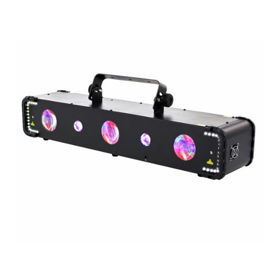
Features Features Special features of the device: 2 strobe arrays each with 18 cold white LEDs, 0.5 W each Grading laser with two laser diodes 2 beam spots each with 192 RGBWA LEDs, 0.12 W each 2 UV LEDs, 3 W each Control via DMX (4 different modes), buttons and display on the unit as well as the supplied infrared remote control 10 preprogrammed automatic shows... -
Page 10: Installation
Installation Installation Unpack and check carefully there is no transportation damage before using the unit. Keep the equipment packaging. To fully protect the product against vibration, dust and moisture during transportation or storage use the original packaging or your own packaging material suitable for transport or storage, respectively. You can install the device standing or hanging. - Page 11 Installation WARNING! Risk of injury caused by falling objects Make sure that the installation complies with the standards and rules that apply in your country. Always secure the device with a secondary safety attachment, such as a safety cable or a safety chain. NOTICE! Risk of overheating The distance between the light output and the illuminated surface must...
- Page 12 Installation Inserting the battery into the remote Press the lock of the battery holder to the centre of the housing and pull out the bat‐ control tery holder like a drawer. Insert the battery. The battery is correct if the positive pole points to the housing base of the remote control.
-
Page 13: Starting Up
Starting up Starting up Create all connections while the device is off. Use the shortest possible high-quality cables for all connections. Take care when running the cables to prevent tripping hazards. Connections in DMX mode Connect the DMX input of the device to the DMX output of a DMX controller or another DMX device. -
Page 14: Connections And Controls
Connections and controls Connections and controls Front panel ö & & & 1 Swivelling mounting bracket 2 Locking screw for the mounting bracket 3 Laser aperture. 4 Strobe LEDs 5 Beam spots 6 UV spots 7 [IR] Infrared sensor for the remote control signals LED effect... - Page 15 Connections and controls 8 [DMX OUT] DMX output, designed as XLR panel socket, 3-pin 9 [POWER OUT] Lockable output socket (Power Twist) for powering a connected device Output current 6 A max. 10 [POWER IN] Lockable input socket (Power Twist) for mains power supply 11 [DMX IN] DMX input, designed as XLR panel plug, 3-pin 12 Display, function buttons and status LEDs...
- Page 16 Connections and controls Infrared remote control Button labelling: Function [AUTO] Enable / disable the automatic mode, selecting programme AUTO MUSIC ON/OFF ‘Au01’ … ‘Au14’ . [MUSIC] Enable / disable the sound-controlled mode, selecting mode ‘So01’ … ‘So14’ . [ON/OFF] Turns the device on and off Buttons for increasing / decreasing the programme run speed.
-
Page 17: Operating
Operating Operating 7.1 Switching the device on / off Switching on Verify that all required laser safety precautions have been taken. Make sure that there is no one in the reach of the laser beam. Connect an external safety switch to the [REMOTE] connection (e.g. an emer‐ gency stop button) or another equivalent device with protection function. -
Page 18: Sound Control
Operating 7.3 Sound control Press [MENU] repeatedly, until the display shows ‘Sou’ and confirm with [ENTER]. Press [UP] or [DOWN] to select between sound-controlled programmes ‘So01’ … ‘So14’ . Confirm the selection with [ENTER]. Use the controller [MIN/MAX] to adjust the sensitivity of the built-in micro‐ phone. -
Page 19: Operating Mode Dmx
Operating 7.4 Operating mode DMX This setting is only relevant if the device is controlled via a DMX controller. Setting the DMX mode Press [MENU] repeatedly, until the display shows ‘dMX’ and confirm with [ENTER]. ð The display shows ‘d 1’ . Press [ENTER] again to open the settings menu for the DMX mode. -
Page 20: System Settings
Operating 7.6 System settings 7.6.1 Display illumination Press [MENU] repeatedly, until the display shows ‘SYS’ and confirm with [ENTER]. Press [UP] or [DOWN] and select ‘LEdS’ and confirm with [ENTER]. Press [UP] or [DOWN] and choose between ‘on’ (display lighting is switched off after 35 seconds) and ‘oFF’... -
Page 21: Menu Overview
Operating 7.8 Menu overview Au01 So01 02Ch SLAV LEdS Au14 S100 So14 d511 05Ch LEdr d508 08Ch rESt d505 U100 10Ch d503 All FX Bar... -
Page 22: Functions In 2-Channel Dmx Mode
Operating 7.9 Functions in 2-channel DMX mode Channel Value Function Automatic show for all components, if channel 2 Sound-controlled automatic show for all compo‐ = 0…250 nents, if channel 2 = 251…255 0…5 Without function Without function 6…22 AUT1 SOU1 23…40 AUT2 SOU2... -
Page 23: Functions In 5-Channel Dmx Mode
Operating 7.10 Functions in 5-channel DMX mode Channel Value Function UV LEDs Automatic show for UV LEDs, if channel 5 = 0… Sound-controlled automatic show for UV LEDs, if channel 5 = 251…255 0…5 Without function Without function 6…55 AP01 SP01 56…106 AP02... - Page 24 Operating Channel Value Function 150…157 AB19 SB19 158…165 AB20 SB20 166…173 AB21 SB21 174…181 AB22 SB22 182…189 AB23 SB23 190…197 AB24 SB24 198…205 AB25 SB25 206…213 AB26 SB26 214…221 AB27 SB27 222…229 AB28 SB28 230…237 AB29 SB29 238…245 AB30 SB30 246…255 ABM (mix programme) SBM (mix programme)
-
Page 25: Functions In 8-Channel Dmx Mode
Operating Channel Value Function 119…141 AF06 SF06 142…163 AF07 SF07 164…186 AF08 SF08 187…209 AF09 SF09 210…232 AF10 SF10 233…255 AFM (mix programme) SFM (mix programme) All components 0…250 Run speed of the automatic show from slow to fast, if channel 1, 2, 3 or 4 = 6…255 251…255 Sensitivity of the music control microphone from low to high, if channel 1, 2, 3 or 4 = 6…255 7.11... - Page 26 Operating Channel Value Function 102…109 AB13 SB13 110…117 AB14 SB14 118…125 AB15 SB15 126…133 AB16 SB16 134…141 AB17 SB17 142…149 AB18 SB18 150…157 AB19 SB19 158…165 AB20 SB20 166…173 AB21 SB21 174…181 AB22 SB22 182…189 AB23 SB23 190…197 AB24 SB24 198…205 AB25 SB25...
- Page 27 Operating Channel Value Function 1…127 Clockwise rotation, speed increasing Laser paused SF01 129…255 Counter-clockwise rotation, speed increasing SF02 Strobe LEDs Automatic show for strobe LEDs Sound-controlled automatic show for strobe LED, if channel 8 = 107…141, 177…211 or 212…255 0…5 Without function Without function 6…27...
-
Page 28: Functions In 10-Channel Dmx Mode
Operating 7.12 Functions in 10-channel DMX mode Channel Value Function UV LED 1 0…255 Dimmer (0 % to 100 %) UV LED 2 0…255 Dimmer (0 % to 100 %) UV LEDs 1 and 2 If channel 1 or 2 = 1…255 0…250 Strobe effect with increasing speed 251…255... - Page 29 Operating Channel Value Function 158…165 AB20 SB20 166…173 AB21 SB21 174…181 AB22 SB22 182…189 AB23 SB23 190…197 AB24 SB24 198…205 AB25 SB25 206…213 AB26 SB26 214…221 AB27 SB27 222…229 AB28 SB28 230…237 AB29 SB29 238…245 AB30 SB30 246…255 ABM (mix programme) SBM (mix programme) 0…255 Run speed of the automatic show, from slow to fast, if channel 4 = 6…255...
- Page 30 Operating Channel Value Function 129…255 Counter-clockwise rotation, speed increasing SF02 Strobe LEDs Automatic show for strobe LEDs, if channel 10 = Sound-controlled automatic show for strobe 0…250 LEDs, if channel 10 = 251…255 0…5 Without function Without function 6…27 AF01 SF01 28…50 AF02...
-
Page 31: Technical Specifications
Technical specifications Technical specifications Light source 2 × strobe arrays: 18 × cold white LEDs 0.5 W each 3 × beam spots: 192 × RGBWA LEDs 0.12 W each 2 × laser: Green 30 mW / 532 nm, red 100 mW / 650 nm 2 ×... - Page 32 Technical specifications Further information Variant group FX bar Similar construction Combination device DMX control Master/Slave Remote control included Sound control Display LED effect...
-
Page 33: Plug And Connection Assignments
Plug and connection assignments Plug and connection assignments Introduction This chapter will help you select the right cables and plugs to connect your valuable equipment so that a perfect light experience is guaranteed. Please take our tips, because especially in ‘Sound & Light’ caution is indicated: Even if a plug fits into a socket, the result of an incorrect connection may be a destroyed DMX controller, a short circuit or ‘just’... -
Page 34: Troubleshooting
Troubleshooting Troubleshooting DANGER! Laser radiation inside During troubleshooting follow the instructions specified in Ä Chapter 2 ‘Safety instructions’ on page 7. Only qualified personnel may carry out service work on the (open) device. Suitable laser protection glasses are required for any activities at the device. -
Page 35: Cleaning
Cleaning Cleaning Optical lenses Clean the optical lenses, that are accessible from the outside, regularly in order to optimize the light output. The frequency of cleaning depends on the operating envi‐ ronment: wet, smoky or particularly dirty surroundings can cause more accumulation of dirt on the optics of the device. -
Page 36: Protecting The Environment
Protecting the environment Protecting the environment Disposal of the packaging material For the packaging, environmentally friendly materials have been chosen that can be supplied to normal recycling. Ensure that plastic bags, packaging, etc. are properly disposed of. Do not just dispose of these materials with your normal household waste, but make sure that they are collected for recycling. - Page 37 Notes All FX Bar...
- Page 38 Notes LED effect...
- Page 40 Musikhaus Thomann · Hans-Thomann-Straße 1 · 96138 Burgebrach · Germany · www.thomann.de...
Need help?
Do you have a question about the Stairville All FX Bar and is the answer not in the manual?
Questions and answers