Table of Contents
Advertisement
Quick Links
Advertisement
Table of Contents

Subscribe to Our Youtube Channel
Related Manuals for thomann Stairville DJ Lase Pro Advanced 2000


Summary of Contents for thomann Stairville DJ Lase Pro Advanced 2000
- Page 1 DJ Lase Pro Advanced 2000 showlaser user manual...
- Page 2 Musikhaus Thomann Thomann GmbH Hans-Thomann-Straße 1 96138 Burgebrach Germany Telephone: +49 (0) 9546 9223-0 E-mail: info@thomann.de Internet: www.thomann.de 11.09.2020, ID: 482998...
-
Page 3: Table Of Contents
Table of contents Table of contents General information..........................5 1.1 Further information........................... 6 1.2 Notational conventions........................7 1.3 Symbols and signal words....................... 8 Safety instructions..........................10 Features............................... 19 Installation..............................20 Starting up..............................27 Connections and operating elements................... 30 Operating..............................38 7.1 Switching the device on / off....................... - Page 4 Table of contents 7.6 Functions in DMX mode........................ 50 7.7 Operating via keyboard......................... 58 7.8 Menu overview..........................66 7.9 Reset to factory defaults........................ 67 Technical specifications........................68 Plug and connection assignment....................71 Troubleshooting............................75 Cleaning............................... 78 Protecting the environment......................79 showlaser...
-
Page 5: General Information
Our products and user manuals are subject to a process of continuous development. We there‐ fore reserve the right to make changes without notice. Please refer to the latest version of the user manual which is ready for download under www.thomann.de. DJ Lase Pro Advanced 2000... -
Page 6: Further Information
General information 1.1 Further information On our website (www.thomann.de) you will find lots of further information and details on the following points: Download This manual is also available as PDF file for you to download. Use the search function in the electronic version to find the topics of Keyword search interest for you quickly. -
Page 7: Notational Conventions
General information 1.2 Notational conventions This manual uses the following notational conventions: Letterings The letterings for connectors and controls are marked by square brackets and italics. Examples: [VOLUME] control, [Mono] button. Displays Texts and values displayed on the device are marked by quotation marks and italics. Examples: ‘24ch’... -
Page 8: Symbols And Signal Words
General information 1.3 Symbols and signal words In this section you will find an overview of the meaning of symbols and signal words that are used in this manual. Signal word Meaning DANGER! This combination of symbol and signal word indicates an immediate dangerous situation that will result in death or serious injury if it is not avoided. - Page 9 General information Warning signs Type of danger Warning – high-voltage. Warning – laser radiation. Warning – dangerous optical radiation. Warning – suspended load. Warning – danger zone. DJ Lase Pro Advanced 2000...
-
Page 10: Safety Instructions
Safety instructions Safety instructions Intended use This device is intended to be used for the projection of laser light effects. It has been designed exclusively for show applications. Use the device only as described in this user manual. Any other use or use under other operating conditions is considered to be improper and may result in personal injury or property damage. - Page 11 Safety instructions Laser safety basics Laser safety requirements are based on DIN EN 60825-1:2015. The corresponding accident pre‐ vention regulation of the Accident Prevention and Insurance Association in Germany is BGV- This device contains a class-4 laser. It comes equipped with a safety key and a jack for con‐ necting an external safety switch.
- Page 12 Safety instructions Safety DANGER! Danger for children Ensure that plastic bags, packaging, etc. are disposed of properly and are not within reach of babies and young children. Choking hazard! Ensure that children do not detach any small parts (e.g. knobs or the like) from the unit.
- Page 13 Safety instructions DANGER! Electric shock caused by short-circuit Always use proper ready-made insulated mains cabling (power cord) with a pro‐ tective contact plug. Do not modify the mains cable or the plug. Failure to do so could result in electric shock/death or fire. If in doubt, seek advice from a regis‐ tered electrician.
- Page 14 Safety instructions WARNING! Eye damage caused by high light intensity Never look directly into the light source. WARNING! Risk of epileptic shock Strobe lighting can trigger seizures in photosensitive epilepsy. Sensitive persons should avoid looking at strobe lights. NOTICE! Laser radiation – risk of fire Keep the area exposed to laser radiation free from flammable substances.
- Page 15 Safety instructions NOTICE! Risk of fire Do not block areas of ventilation. Do not install the device near any direct heat source. Keep the device away from naked flames. DJ Lase Pro Advanced 2000...
- Page 16 Safety instructions NOTICE! Operating conditions This device has been designed for indoor use only. To prevent damage, never expose the device to any liquid or moisture. Avoid direct sunlight, heavy dirt, and strong vibrations. Only operate the device within the ambient conditions specified in the chapter ‘Technical specifications’...
- Page 17 Safety instructions NOTICE! Power supply Before connecting the device, ensure that the input voltage (AC outlet) matches the voltage rating of the device and that the AC outlet is protected by a residual current circuit breaker. Failure to do so could result in damage to the device and possibly injure the user.
- Page 18 Safety instructions NOTICE! Possible staining The plasticiser contained in the rubber feet of this product may possibly react with the coating of your parquet, linoleum, laminate or PVC floor and after some time cause permanent dark stains. In case of doubt, do not put the rubber feet directly on the floor, but use felt-pad floor protectors or a carpet.
-
Page 19: Features
Features Features Professional RGB laser for use in all event areas: Colour mixing based on analogue diode modulation Laser power: 2000 mW Laser class: 4 Control options: – DMX-512 (20 channels) – ILDA – IR remote control (included) – built-in buttons and display –... -
Page 20: Installation
Installation Installation Unpack and check carefully there is no transportation damage before using the unit. Keep the equipment packaging. To fully protect the product against vibration, dust and moisture during transportation or storage use the original packaging or your own packaging material suitable for transport or storage, respectively. - Page 21 Installation Safety switch (emergency stop) Connect the external safety switch (not supplied) to the provided connection socket on the device. If you press the external switch, the laser beam will be switched off immediately. Observe the safety instructions of the switch manufacturer and the regulations for the intended use.
- Page 22 Installation Minimum height In order to meet the limits for maximum irradiation (MZB limit value for the non-hazardous irradiation of the eye or the skin with a laser), the device must be installed at a height of at least 2.7 m according to the BGV-B2 valid in Germany. The determination of the MZB limit values depends on the specific environmental conditions in individual cases and must be carried out by the responsible laser protection representative on site, based on the applicable standard DIN EN 60825-1.
- Page 23 Installation DANGER! Follow the instructions in the chapter titled "Safety Instructions" in the user manual. To avoid laser emission, remove the safety key before you start to install the device. WARNING! Stray laser radiation Inadequately secured additional components may cause stray laser radiation. Make sure that all additional components are adequately secured.
- Page 24 Installation NOTICE! Risk of overheating The distance between the light output and the illuminated surface must be more than 2.0 m (78.7 in). Always ensure sufficient ventilation. The ambient temperature must always be below 40 °C (104 °F). showlaser...
- Page 25 Installation Inserting the battery into the Press the lock of the battery holder to the centre of the housing and pull out the battery holder remote control like a drawer. Insert the battery. The battery is correct if the positive pole points to the housing base of the remote control.
- Page 26 Installation NOTICE! Possible damage by leaking batteries Leaking batteries can cause permanent damage to the device. Take batteries out of the device if it is not going to be used for a longer period. NOTICE! Risk of fire due to incorrect polarity Incorrectly inserted batteries may destroy the device or the batteries.
-
Page 27: Starting Up
Starting up Starting up Create all connections while the device is off. Use the shortest possible high-quality cables for all connections. Take care when running the cables to prevent tripping hazards. DANGER! Laser radiation Follow the instructions in the chapter titled "Safety Instructions" in this manual. NOTICE! Possible data transmission errors For error-free operation make use of dedicated DMX cables and do not use ordi‐... - Page 28 Starting up Connections in DMX mode Connect the DMX input of the device to the DMX output of a DMX controller or another DMX device. Connect the output of the first DMX device to the input of the second one, and so on to form a daisy chain.
- Page 29 Starting up Connections in master/slave When you configure a group of devices in master/slave mode, the first unit will control the mode other units for an automatic, sound-activated, synchronized show. This function is ideal when you want to start a show immediately. Connect the DMX output of the master device to the DMX input of the first slave device.
-
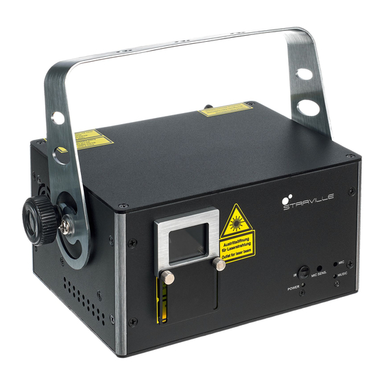
Page 30: Connections And Operating Elements
Connections and operating elements Connections and operating elements Front panel showlaser... - Page 31 Connections and operating elements 1 Laser aperture. 2 Retainer and mounting bracket 3 Locking screw for the retainer and mounting bracket 4 [MIC] Microphone for sound-controlled operation 5 [MUSIC] Indicator LED, flashes blue in sound-controlled operation 6 [MIC SENS.] Rotary control for adjusting the sensitivity of the built-in microphone for sound control 7 [POWER] Indicator LED, lights steady white when the unit is on 8 [IR]...
- Page 32 Connections and operating elements Rear panel showlaser...
- Page 33 Connections and operating elements 9 Safety cable eyelet. 10 [POWER] Indicator LED, lights steady white when the unit is on 11 [LASER] Indicator LED, lights steady red when the laser is on (key switch in [ON] position 12 Display 13 [ILDA THROUGH] 25-pin ILDA output connector for looping through the ILDA signal to other devices 14 [ILDA INPUT] 25-pin ILDA input socket...
- Page 34 Connections and operating elements 17 Function and control buttons [MENU]: Opens the main menu. Skips back to the previous menu item. [UP]: Increases the displayed value by one. [DOWN]: Decreases the displayed value by one. [ENTER]: Selects an option of the respective operating mode, confirms the set value. 18 [PS 2] Connection sockets for the supplied USB keyboard or the USB adapter 19 Safety key switch: switches the laser output on or off.
- Page 35 Connections and operating elements IR remote control DJ Lase Pro Advanced 2000...
- Page 36 Connections and operating elements 1 On / off switch. When the device is in the ‘Auto Show’ mode or is performing a self test, press the button for several seconds to enter the ‘Remote control’ mode. When the device is already in the ‘Remote control’ mode, this button switches the laser on or off. 2 Colour selection button.
- Page 37 Connections and operating elements [C]: Press the button to switch to the TEXT mode. Select a button on the numeric key pad between [0] … [9] to select the desired preset text mode that will be projected onto a surface. 7 Colour selection button.
-
Page 38: Operating
Operating Operating 7.1 Switching the device on / off Switching on Perform the following steps to switch the device on: Verify that all required laser safety precautions have been taken. Make sure that there is no one in the reach of the laser beam. Connect an external safety switch to the [REMOTE] connection (e.g. -
Page 39: Main Menu
Operating Turning off Perform the following steps to switch the device off: Turn the safety key to the ‘OFF’ position to turn the laser beam off and remove the key. Keep the safety key under control. Turn off the power using the mains switch. Additionally, you can disconnect the device from the mains. -
Page 40: System Menu
Operating 7.3 SYSTEM menu In this menu, you can adjust various device settings. Press [MENU] to open the main menu. Press repeatedly [MENU] or [UP] and [DOWN] to select the ‘SYS’ menu and confirm with [ENTER]. Parameter Meaning Value range ‘Nirr’... - Page 41 Operating Change the currently displayed value with [UP] and [DOWN] and confirm with [ENTER]. To return to the main menu without making changes, press [MENU]. DJ Lase Pro Advanced 2000...
-
Page 42: Operating Modes
Operating 7.4 Operating modes Operating mode AUTO In this mode, the device automatically projects programmed patterns in the selected mode onto a surface. Press [MENU] to open the main menu. Press repeatedly [MENU] or [UP] and [DOWN] to select the menu item ‘Aut’ and confirm with [ENTER]. - Page 43 Operating Parameter Meaning ‘Aut 5’ Auto mode 5, show with programmed ‘Love’ motto patterns ‘Aut 6’ Auto mode 6, show with programmed ‘Birthday’ motto patterns ‘Aut 7’ Auto mode 7, show with programmed ‘Party’ motto patterns ‘Aut 8’ Auto mode 8, show with programmed ‘Halloween’ motto patterns ‘Aut 9’...
- Page 44 Operating Operating mode SOUND In this mode, the device projects programmed patterns sound-controlled onto a surface. Set the sensitivity of the built-in microphone using the adjustment screw [MIC SENS.] on the front panel of the housing. Press [MENU] to open the main menu. Press repeatedly [MENU] or [UP] and [DOWN] to select the menu item ‘Sou’...
- Page 45 Operating Parameter Meaning ‘Sou 5’ Sound mode 5, show with programmed ‘Love’ motto patterns ‘Sou 6’ Sound mode 6, show with programmed ‘Birthday’ motto patterns ‘Sou 7’ Sound mode 7, show with programmed ‘Party’ motto patterns ‘Sou 8’ Sound mode 8, show with programmed ‘Halloween’ motto pat‐ terns ‘Sou 9’...
- Page 46 Operating Operating mode TEXT In this mode, the device projects text that has been entered and stored via the supplied key‐ board (see Ä Chapter 7.7 ‘Operating via keyboard’ on page 58) onto a surface. Press [MENU] to open the main menu. Press repeatedly [MENU] or [UP] and [DOWN] to select the menu item ‘tXt’...
- Page 47 Operating Operating mode TIME In this mode, the device consecutively projects time, date and the day of the week onto a sur‐ face. Press [MENU] to open the main menu. Press repeatedly [MENU] or [UP] and [DOWN] to select the menu item ‘tiM’ and confirm with [ENTER].
- Page 48 Operating Operating mode COUNTDOWN In this mode, the device projects a linked text ( ‘t-01’ … ‘t-09’ ) after a programmed countdown time onto a surface. Press [MENU] to open the main menu. Press repeatedly [MENU] or [UP] and [DOWN] to select the menu item ‘Cut’ and confirm with [ENTER].
-
Page 49: Setting Dmx Channel
Operating Operating mode SLAVE In this mode, the device exactly follows the operation of the master that it is connected to. Press [MENU] to open the main menu. Press repeatedly [MENU] or [UP] and [DOWN] to select the menu item ‘SLA’ and confirm with [ENTER]. -
Page 50: Functions In Dmx Mode
Operating 7.6 Functions in DMX mode Channel Value Function Operating mode selection 0 … 9 Laser off 10 … 49 Auto mode 50 … 99 Sound mode 100 … 149 Text mode 150 … 199 Selecting the first pattern 200 … 255 Selecting the second pattern Auto mode, channel 1 = 10 …... - Page 51 Operating Channel Value Function 90 … 119 AUTO4 120 … 149 AUTO5 150 … 179 AUTO6 180 … 209 AUTO7 210 … 239 AUTO8 240 … 255 AUTO9 Sound mode, channel 1 = 50 … 99 0 … 29 MUSIC1 30 …...
- Page 52 Operating Channel Value Function 180 … 209 MUSIC7 210 … 239 MUSIC8 240 … 255 MUSIC9 Pattern mode, channel 1 = 150 … 255 0 … 31 Pattern group 1 32 … 63 Pattern group 2 64 … 95 Pattern group 3 96 …...
- Page 53 Operating Channel Value Function 0 … 255 Patterns 1 to 16 of the respectively selected group of channel 2 (16 patterns x 8 groups = 128 patterns) Colour selection 0 … 7 Automatic 8 … 15 16 … 23 Green 24 …...
- Page 54 Operating Channel Value Function 160 … 207 Multi-coloured motion left to right, increasing speed 208 … 255 Strobe effect, increasing speed Drawing of pattern (clipping) Original pattern, no Clipping effect 1 … 127 Build-up of patterns 0 % to 99 % 128 …...
- Page 55 Operating Channel Value Function Y-axis rotation 0 … 127 Fixed adjusted position of Y-axis 128 … 191 Y-axis rotation clockwise 192 … 255 Y-axis rotation counterclockwise Rotation speed of Y-axis 0 … 255 Rotation speed of Y-axis from fast to slow X-axis rotation 0 …...
- Page 56 Operating Channel Value Function 0 … 127 Fixed adjusted position of Z-axis 128 … 191 Z-axis rotation clockwise 192 … 255 Z-axis rotation counterclockwise Rotation speed of Z-axis 0 … 255 Rotation speed of Z-axis from fast to slow Motion on X-axis 0 …...
- Page 57 Operating Channel Value Function 128 … 191 Rotation around Y-axis clockwise 192 … 255 Rotation around Y-axis counterclockwise Motion speed on Y-axis 0 … 255 Motion speed of Y-axis from fast to slow Wave effect 0 … 255 Increasing wave size Wave effect 0 …...
-
Page 58: Operating Via Keyboard
Operating 7.7 Operating via keyboard The functions of the device can also be controlled via the supplied keyboard. The following tables show the key layout in the different operating modes. General functions Button Symbol Function Windows® Start button, opens the main menu. Use the arrow keys and to switch between the menu options. - Page 59 Operating Functions in AUTO mode Button Symbol Function [Pause] Stops the running program in the motion of the currently projected pattern. Press the button again to let the programme continue. [RGB | Selects the most recently edited text. Color] [Mirror] Displays the stored text in an endless loop.
- Page 60 Operating Functions in TEXT mode Button Symbol Function [Flow] Enables the Marquee function: the entered text will be projected circumferentially. The running speed can be adjusted with the arrow buttons and . Press the button again to deactivate the function. [RGB | Manual switching between different colour effects while the projec‐...
- Page 61 Operating Button Symbol Function [Y Move] Activates the motion in the Y direction: the entered text moves up from below and back. The motion speed can be adjusted with the arrow buttons and . Press the button again to deactivate the function.
- Page 62 Operating Button Symbol Function [Text Qty.] Activates the selection of the number of characters: with the arrow buttons and the number of characters to be displayed (12, 10, 8, 6 or 4 characters) can be selected. Press the button again to deacti‐ vate the function.
- Page 63 Operating Button Symbol Function [Save] Save key. Hold down this key and use the number keys on the key‐ board to set the desired memory location (1 … 9). The entered text is now saved to this memory location. [Play] Save key.
- Page 64 Operating Functions in TIME mode Button Symbol Function [Show Activates the display mode: use the arrow buttons and to select Mode] the display mode: only time or time and date. Press to store the setting. [Setting] Activates the time setting: use the arrow buttons and to set the date and time.
- Page 65 Operating Functions in COUNTDOWN The display flashes in the activated COUNTDOWN mode. Set the desired countdown using the mode number keys on the keyboard (1 … 9). Press to store the setting. Button Symbol Function [Back Delete key. Use this button to delete the last character of the Space] entered text.
-
Page 66: Menu Overview
Operating 7.8 Menu overview showlaser... -
Page 67: Reset To Factory Defaults
Operating 7.9 Reset to factory defaults To reset the device to factory default settings, open the SYSTEM menu (see Ä Chapter 7.3 ‘SYSTEM menu’ on page 40), select the menu item ‘rSET’ and confirm with [ENTER]. All settings are reset immediately without prompting. DJ Lase Pro Advanced 2000... -
Page 68: Technical Specifications
Technical specifications Technical specifications Laser medium Red: 638 nm (typical), LD Green: 520 nm (typical), LD Blue: 450 nm (typical), LD Laser power Red: 500 mW Green: 500 mW Blue: 1000 mW Laser classification according to EN 60825-1 2015 Beam diameter at aperture <... - Page 69 Technical specifications Deflection angle 1 … 36° Input connections Voltage supply IEC chassis plug C14 ILDA Input/ILDA Through 2 × 25-pin ILDA input socket DMX control XLR chassis plug, 3-pin Output connections DMX control XLR chassis socket, 3-pin Number of DMX channels Operating supply voltage 100 …...
- Page 70 Technical specifications Further information Colour spectrum Animation laser Grating laser Analogue modulation showlaser...
-
Page 71: Plug And Connection Assignment
Plug and connection assignment Plug and connection assignment Introduction This chapter will help you select the right cables and plugs to connect your valuable equip‐ ment so that a perfect light experience is guaranteed. Please take our tips, because especially in ‘Sound & Light’ caution is indicated: Even if a plug fits into a socket, the result of an incorrect connection may be a destroyed DMX controller, a short circuit or ‘just’... - Page 72 Plug and connection assignment ILDA interface You can connect laser control units, that generate signals as standardized by the International Laser Display Association to the ILDA input. The ILDA output of the unit can be connected to other laser devices. The ILDA interfaces are designed as 25-pin D-sub connectors.
- Page 73 Plug and connection assignment User-defined signal 4+ Return signal from the unit Shutter X– Y– Intensity– Locking (Interlock) B R– G– B– User-defined signal 1– User-defined signal 2– User-defined signal 3– DJ Lase Pro Advanced 2000...
- Page 74 Plug and connection assignment User-defined signal 4– Ground showlaser...
-
Page 75: Troubleshooting
Troubleshooting Troubleshooting DANGER! Laser radiation inside Follow the instructions in the chapter titled "Safety Instructions" in this manual. Only qualified personnel may carry out service work on the (open) device. Suitable laser protection glasses are required for any activities at the device. In the following we list a few common problems that may occur during operation. - Page 76 Troubleshooting Symptom Remedy Device not working, no light, fan not working. 1. Check the power connection and main fuse. 2. Check the safety key switch. 3. Check the external safety switch (e.g. emergency stop). No response to the DMX controller 1.
- Page 77 If the device receives a signal from the remote control the ‘MUSIC’ lights up briefly. 3. Check the remote control battery. If the procedures recommended above do not succeed, please contact our Service Center. You can find the contact information at www.thomann.de. DJ Lase Pro Advanced 2000...
-
Page 78: Cleaning
Cleaning Cleaning DANGER! Laser radiation Follow the instructions in the chapter titled "Safety Instructions" in this manual. To avoid laser emission, remove the safety key before you start to clean the device. Optical lenses Clean the optical lenses, that are accessible from the outside, regularly in order to optimize the light output. -
Page 79: Protecting The Environment
Protecting the environment Protecting the environment Disposal of the packaging mate‐ rial For the transport and protective packaging, environmentally friendly materials have been chosen that can be supplied to normal recycling. Ensure that plastic bags, packaging, etc. are properly disposed of. Do not just dispose these materials with your normal household waste, but make sure that they are fed to a recovery. - Page 80 Protecting the environment Disposal of your old device This product is subject to the European Waste Electrical and Electronic Equipment Directive (WEEE) in its currently valid version. Do not dispose with your normal household waste. Dispose this device through an approved waste disposal firm or through your local waste facility.
- Page 81 Notes DJ Lase Pro Advanced 2000...
- Page 82 Notes showlaser...
- Page 84 Musikhaus Thomann · Hans-Thomann-Straße 1 · 96138 Burgebrach · Germany · www.thomann.de...
Need help?
Do you have a question about the Stairville DJ Lase Pro Advanced 2000 and is the answer not in the manual?
Questions and answers