Table of Contents
Advertisement
Advertisement
Table of Contents

Related Manuals for thomann STAIRVILLE Strip Blinder LED RGB WW


Summary of Contents for thomann STAIRVILLE Strip Blinder LED RGB WW
- Page 1 Strip Blinder LED RGB WW LED bar user manual...
- Page 2 Musikhaus Thomann Thomann GmbH Hans-Thomann-Straße 1 96138 Burgebrach Germany Telephone: +49 (0) 9546 9223-0 E-mail: info@thomann.de Internet: www.thomann.de 08.03.2018, ID: 421283...
-
Page 3: Table Of Contents
Table of contents Table of contents General notes............................... 5 Safety instructions............................. 8 Features............................... 13 Installation..............................14 Starting up..............................17 Connections and controls........................20 Operating..............................23 7.1 Main menu............................23 7.2 Functions in 4-channel DMX mode (1 pixel, 8 bit)............... 27 7.3 Functions in 6-channel DMX mode (8 bit)................ - Page 4 Table of contents 7.9 Functions in 40-channel DMX mode (10 pixels, 8 bit)............36 7.10 Functions in 40-channel DMX mode (5 pixels, 16 bit)............40 7.11 Functions in 80-channel DMX mode (10 pixels, 16 bit)........... 43 7.12 Menu overview..........................51 Technical specifications........................
-
Page 5: General Notes
General notes General notes This user manual contains important information on safe operation of the device. Read and follow all safety notes and all instructions. Save this manual for future reference. Make sure that it is available to all persons using this device. If you sell the device, include the manual for the next owner. - Page 6 General notes Signal word Meaning DANGER! This combination of symbol and signal word indicates an immediate dangerous situation that will result in death or serious injury if it is not avoided. WARNING! This combination of symbol and signal word indicates a pos- sible dangerous situation that can result in death or serious injury if it is not avoided.
- Page 7 General notes Warning signs Type of danger Warning – danger zone. Strip Blinder LED RGB WW...
-
Page 8: Safety Instructions
Safety instructions Safety instructions Intended use This device is intended to be used as an electronic illumination effect using LED technics. The device is designed for professional use and is not suitable for use in households. Use the device only as described in this user manual. Any other use or use under other operating con- ditions is considered to be improper and may result in personal injury or property damage. - Page 9 Safety instructions Safety DANGER! Danger for children Ensure that plastic bags, packaging, etc. are disposed of properly and are not within reach of babies and young children. Choking hazard! Ensure that children do not detach any small parts (e.g. knobs or the like) from the unit.
- Page 10 Safety instructions DANGER! Electric shock caused by short-circuit Always use proper ready-made insulated mains cabling (power cord) with a pro- tective contact plug. Do not modify the mains cable or the plug. Failure to do so could result in electric shock/death or fire. If in doubt, seek advice from a regis- tered electrician.
- Page 11 Safety instructions NOTICE! Risk of fire Do not block areas of ventilation. Do not install the device near any direct heat source. Keep the device away from naked flames. NOTICE! Operating conditions This device has been designed for indoor use only. To prevent damage, never expose the device to any liquid or moisture.
- Page 12 Safety instructions NOTICE! Power supply Before connecting the device, ensure that the input voltage (AC outlet) matches the voltage rating of the device and that the AC outlet is protected by a residual current circuit breaker. Failure to do so could result in damage to the device and possibly injure the user.
-
Page 13: Features
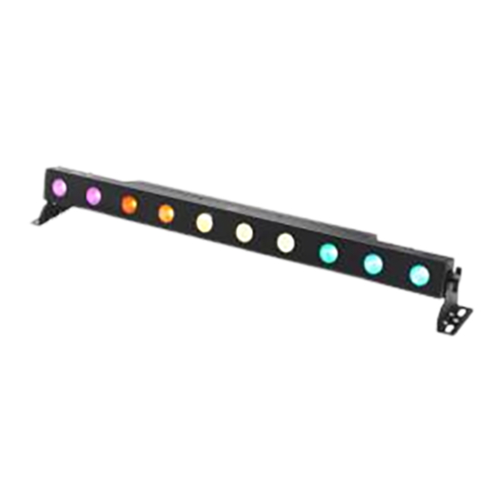
Features Features Special features of the device: 10 four-colour LEDs (RGBWW, 10 W each) Control via DMX (ten different modes), via RDM and via buttons and display on the unit Built-in automatic show programmes Master / Slave mode Robust metal housing with compact design Versatile placement and mounting options Looped through mains voltage output for powering further devices Remote Device Management... -
Page 14: Installation
Installation Installation Unpack and carefully check that there is no transportation damage before using the unit. Keep the equipment packaging. To fully protect the device against vibration, dust and moisture during transportation or storage use the original packaging or your own packaging material suitable for transport or storage, respectively. - Page 15 Installation NOTICE! Risk of overheating Always ensure sufficient ventilation. The ambient temperature must always be below 40 °C (104 °F). NOTICE! Use of stands When mounting the device onto a stand, ensure that the stand is in a safe and stable position and that the weight of the device does not exceed the maximum permissible load capacity of the stand.
- Page 16 Installation NOTICE! Possible data transmission errors For error-free operation make use of dedicated DMX cables and do not use ordi- nary microphone cables. Never connect the DMX input or output to audio devices such as mixers or ampli- fiers. Please note that this device must not be connected to a dimmer. LED bar...
-
Page 17: Starting Up
Starting up Starting up Create all connections while the device is off. Use the shortest possible high-quality cables for all connections. Take care when running the cables to prevent tripping hazards. Strip Blinder LED RGB WW... - Page 18 Starting up Connections in DMX mode Connect the DMX input of the device to the DMX output of a DMX controller or another DMX device. Connect the output of the first DMX device to the input of the second one, and so on to form a daisy chain.
- Page 19 Starting up Connections in master/slave When you configure a group of devices in master/slave mode, the first unit will control the mode other units for an automatic, sound-activated, synchronized show. This function is ideal when you want to start a show immediately. Connect the DMX output of the master device to the DMX input of the first slave device.
-
Page 20: Connections And Controls
Connections and controls Connections and controls LED bar... - Page 21 Connections and controls 1 [POWER OUTPUT] Lockable output socket (Power Twist) for the power supply of further units. 2 [RDM/DMX OUTPUT] RDM / DMX output 3 [FUSE] Fuse holder 4 [POWER] Main switch. Turns the device on and off. 5 [RDM/DMX INPUT] RDM / DMX input 6 [POWER INPUT] Lockable input socket (Power Twist) for power supply.
- Page 22 Connections and controls 8 [POWER] The red LED lights up when the unit is operational after power up. 9 [RDM/DMX] The green control LED indicates that a signal is being received at the RDM/DMX input. 10 Button [DOWN] Navigates downwards in a menu list. Decreases the displayed value by one. 11 Button [ENTER] Activates the main menu and toggles between menu items.
-
Page 23: Operating
Operating Operating 7.1 Main menu Press [MENU] to activate the main menu. Use [ENTER] to select a submenu. When the display shows the desired submenu, press [UP] or [DOWN] to change the indicated value. To close the sub menu, press [MODE]. If you don't press any button for about 45 seconds, the buttons will be locked and the display turns off. - Page 24 Operating The following table shows the setting options. Main menu Menu level 2 Menu level 3 Menu level 4 Meaning ‘DMX’ ‘DMX Ch’ Selecting a DMX mode ‘1 pixel’ 4-channel mode (with 8 bit res- olution) 8-channel mode (with 16 bit resolution) ‘2 pixel’...
- Page 25 Operating Main menu Menu level 2 Menu level 3 Menu level 4 Meaning ‘5 pixel’ 20-channel mode (with 8 bit resolution) 40-channel mode (with 16 bit resolution) ‘10 pixel’ 40-channel mode (with 8 bit resolution) 80-channel mode (with 16 bit resolution) ‘9 DMX Ch’...
- Page 26 Operating Main menu Menu level 2 Menu level 3 Menu level 4 Meaning ‘Fade off’ Response to DMX commands with a slight delay ‘Chase’ Preprogrammed automatic show ‘Program’ Selecting a show ‘prog’ ‘prog:01’ … ‘prog:10’ ‘Speed’ Running speed ‘speed’ ‘speed:01’ … ‘speed:99’ ‘Fade’...
-
Page 27: Functions In 4-Channel Dmx Mode (1 Pixel, 8 Bit)
Operating Main menu Menu level 2 Menu level 3 Menu level 4 Meaning ‘Red’ ‘R:000’ … ‘R:255’ Intensity red (0 % to 100 %) ‘Green’ ‘G:000’ … ‘G:255’ Intensity green (0 % to 100 %) ‘Blue’ ‘B:000’ … ‘B:255’ Intensity blue (0 % to 100 %) ‘White’... -
Page 28: Functions In 6-Channel Dmx Mode (8 Bit)
Operating Channel Value Function 0…255 Intensity blue (0 % to 100 %) 0…255 Intensity white (0 % to 100 %) 7.3 Functions in 6-channel DMX mode (8 bit) Channel Value Function 0…255 Intensity red (0 % to 100 %) 0…255 Intensity green (0 % to 100 %) 0…255 Intensity blue (0 % to 100 %) -
Page 29: Functions In 8-Channel Dmx Mode (2 Pixels, 8 Bit)
Operating Channel Value Function 0…239 Strobe effect, increasing speed 240…255 No strobe effect (full on) 7.4 Functions in 8-channel DMX mode (2 pixels, 8 bit) Channel Value Function 0…255 Intensity red (0 % to 100 %), LEDs 1…5 0…255 Intensity green (0 % to 100 %), LEDs 1…5 0…255 Intensity blue (0 % to 100 %), LEDs 1…5 0…255... -
Page 30: Functions In 8-Channel Dmx Mode (1 Pixel, 16 Bit)
Operating Channel Value Function 0…255 Intensity blue (0 % to 100 %), LEDs 6…10 0…255 Intensity white (0 % to 100 %), LEDs 6…10 7.5 Functions in 8-channel DMX mode (1 pixel, 16 bit) Channel Value Function 1 (upper byte) 0…65535 Intensity red (0 % to 100 %) 2 (lower byte) -
Page 31: Functions In 9-Channel Dmx Mode (8 Bit)
Operating Channel Value Function 5 (upper byte) 0…65535 Intensity blue (0 % to 100 %) 6 (lower byte) 7 (upper byte) 0…65535 Intensity white (0 % to 100 %) 8 (lower byte) 7.6 Functions in 9-channel DMX mode (8 bit) Channel Value Function... - Page 32 Operating Channel Value Function Operating mode 0…15 All LEDs light up (full on RGBW) 16…127 Colour selection 128…255 Selecting a automatic show 0…255 Running speed automatic show, increasing 0…255 Fade effect, increasing speed 0…255 Dimmer (0 % to 100 %) Strobe effect 0…239 Strobe effect, increasing speed...
-
Page 33: Functions In 16-Channel Dmx Mode (2 Pixels, 16 Bit)
Operating 7.7 Functions in 16-channel DMX mode (2 pixels, 16 bit) Channel Value Function 1 (upper byte) 0…65535 Intensity red (0 % to 100 %), LEDs 1…5 2 (lower byte) 3 (upper byte) 0…65535 Intensity green (0 % to 100 %), LEDs 1…5 4 (lower byte) 5 (upper byte) 0…65535... -
Page 34: Functions In 20-Channel Dmx Mode (5 Pixels, 8 Bit)
Operating Channel Value Function 13 (upper byte) 0…65535 Intensity blue (0 % to 100 %), LEDs 6…10 14 (lower byte) 15 (upper byte) 0…65535 Intensity white (0 % to 100 %), LEDs 6…10 16 (lower byte) 7.8 Functions in 20-channel DMX mode (5 pixels, 8 bit) Channel Value Function... -
Page 35: Strip Blinder Led Rgb Ww
Operating Channel Value Function 0…255 Intensity red (0 % to 100 %), LEDs 3, 4 0…255 Intensity green (0 % to 100 %), LEDs 3, 4 0…255 Intensity blue (0 % to 100 %), LEDs 3, 4 0…255 Intensity white (0 % to 100 %), LEDs 3, 4 0…255 Intensity red (0 % to 100 %), LEDs 5, 6 0…255... -
Page 36: Functions In 40-Channel Dmx Mode (10 Pixels, 8 Bit)
Operating Channel Value Function 0…255 Intensity green (0 % to 100 %), LEDs 9, 10 0…255 Intensity blue (0 % to 100 %), LEDs 9, 10 0…255 Intensity white (0 % to 100 %), LEDs 9, 10 7.9 Functions in 40-channel DMX mode (10 pixels, 8 bit) Channel Value Function... - Page 37 Operating Channel Value Function 0…255 Intensity green (0 % to 100 %), LED 2 0…255 Intensity blue (0 % to 100 %), LED 2 0…255 Intensity white (0 % to 100 %), LED 2 0…255 Intensity red (0 % to 100 %), LED 3 0…255 Intensity green (0 % to 100 %), LED 3 0…255...
- Page 38 Operating Channel Value Function 0…255 Intensity blue (0 % to 100 %), LED 5 0…255 Intensity white (0 % to 100 %), LED 5 0…255 Intensity red (0 % to 100 %), LED 6 0…255 Intensity green (0 % to 100 %), LED 6 0…255 Intensity blue (0 % to 100 %), LED 6 0…255...
- Page 39 Operating Channel Value Function 0…255 Intensity white (0 % to 100 %), LED 8 0…255 Intensity red (0 % to 100 %), LED 9 0…255 Intensity green (0 % to 100 %), LED 9 0…255 Intensity blue (0 % to 100 %), LED 9 0…255 Intensity white (0 % to 100 %), LED 9 0…255...
-
Page 40: Functions In 40-Channel Dmx Mode (5 Pixels, 16 Bit)
Operating 7.10 Functions in 40-channel DMX mode (5 pixels, 16 bit) Channel Value Function 1 (upper byte) 0…65535 Intensity red (0 % to 100 %), LEDs 1, 2 2 (lower byte) 3 (upper byte) 0…65535 Intensity green (0 % to 100 %), LEDs 1, 2 4 (lower byte) 5 (upper byte) 0…65535... - Page 41 Operating Channel Value Function 13 (upper byte) 0…65535 Intensity blue (0 % to 100 %), LEDs 3, 4 14 (lower byte) 15 (upper byte) 0…65535 Intensity white (0 % to 100 %), LEDs 3, 4 16 (lower byte) 17 (upper byte) 0…65535 Intensity red (0 % to 100 %), LEDs 5, 6 18 (lower byte)
- Page 42 Operating Channel Value Function 25 (upper byte) 0…65535 Intensity red (0 % to 100 %), LEDs 7, 8 26 (lower byte) 27 (upper byte) 0…65535 Intensity green (0 % to 100 %), LEDs 7, 8 28 (lower byte) 29 (upper byte) 0…65535 Intensity blue (0 % to 100 %), LEDs 7, 8 30 (lower byte)
-
Page 43: Functions In 80-Channel Dmx Mode (10 Pixels, 16 Bit)
Operating Channel Value Function 37 (upper byte) 0…65535 Intensity blue (0 % to 100 %), LEDs 9, 10 38 (lower byte) 39 (upper byte) 0…65535 Intensity white (0 % to 100 %), LEDs 9, 10 40 (lower byte) 7.11 Functions in 80-channel DMX mode (10 pixels, 16 bit) Channel Value Function... - Page 44 Operating Channel Value Function 5 (upper byte) 0…65535 Intensity blue (0 % to 100 %), LED 1 6 (lower byte) 7 (upper byte) 0…65535 Intensity white (0 % to 100 %), LED 1 8 (lower byte) 9 (upper byte) 0…65535 Intensity red (0 % to 100 %), LED 2 10 (lower byte) 11 (upper byte)
- Page 45 Operating Channel Value Function 17 (upper byte) 0…65535 Intensity red (0 % to 100 %), LED 3 18 (lower byte) 19 (upper byte) 0…65535 Intensity green (0 % to 100 %), LED 3 20 (lower byte) 21 (upper byte) 0…65535 Intensity blue (0 % to 100 %), LED 3 22 (lower byte) 23 (upper byte)
- Page 46 Operating Channel Value Function 29 (upper byte) 0…65535 Intensity blue (0 % to 100 %), LED 4 30 (lower byte) 31 (upper byte) 0…65535 Intensity white (0 % to 100 %), LED 4 32 (lower byte) 33 (upper byte) 0…65535 Intensity red (0 % to 100 %), LED 5 34 (lower byte) 35 (upper byte)
- Page 47 Operating Channel Value Function 41 (upper byte) 0…65535 Intensity red (0 % to 100 %), LED 6 42 (lower byte) 43 (upper byte) 0…65535 Intensity green (0 % to 100 %), LED 6 44 (lower byte) 45 (upper byte) 0…65535 Intensity blue (0 % to 100 %), LED 6 46 (lower byte) 47 (upper byte)
- Page 48 Operating Channel Value Function 53 (upper byte) 0…65535 Intensity blue (0 % to 100 %), LED 7 54 (lower byte) 55 (upper byte) 0…65535 Intensity white (0 % to 100 %), LED 7 56 (lower byte) 57 (upper byte) 0…65535 Intensity red (0 % to 100 %), LED 8 58 (lower byte) 59 (upper byte)
- Page 49 Operating Channel Value Function 65 (upper byte) 0…65535 Intensity red (0 % to 100 %), LED 9 66 (lower byte) 67 (upper byte) 0…65535 Intensity green (0 % to 100 %), LED 9 68 (lower byte) 69 (upper byte) 0…65535 Intensity blue (0 % to 100 %), LED 9 70 (lower byte) 71 (upper byte)
- Page 50 Operating Channel Value Function 77 (upper byte) 0…65535 Intensity blue (0 % to 100 %), LED 10 78 (lower byte) 79 (upper byte) 0…65535 Intensity white (0 % to 100 %), LED 10 80 (lower byte) LED bar...
-
Page 51: Menu Overview
Operating 7.12 Menu overview Strip Blinder LED RGB WW... -
Page 52: Technical Specifications
Technical specifications Technical specifications Number of DMX channels 4, 6, 9, 16, 20, 40 or 80, depending on operating mode Illuminant 10 four-colour LEDs (RGBWW, 10 W each) Beam angle approx. 18° Operating supply voltage 100 – 240 V 50/60 Hz Power consumption max. - Page 53 Technical specifications Strip Blinder LED RGB WW...
-
Page 54: Plug And Connection Assignment
Plug and connection assignment Plug and connection assignment Introduction This chapter will help you select the right cables and plugs to connect your valuable equip- ment so that a perfect light experience is guaranteed. Please take our tips, because especially in ‘Sound & Light’ caution is indicated: Even if a plug fits into a socket, the result of an incorrect connection may be a destroyed DMX controller, a short circuit or ‘just’... -
Page 55: Troubleshooting
Troubleshooting Troubleshooting NOTICE! Possible data transmission errors For error-free operation make use of dedicated DMX cables and do not use ordi- nary microphone cables. Never connect the DMX input or output to audio devices such as mixers or ampli- fiers. In the following we list a few common problems that may occur during operation. - Page 56 Troubleshooting Symptom Remedy The unit does not work, no light, Check the mains connection and the main fuse. the display is dark Apparently no function despite Check if the unit is in DMX mode or in ‘slave’ mode. If so, proper power supply check the unit in another mode.
- Page 57 DMX interface circuit. If the procedures recommended above do not succeed, please contact our Service Center. You can find the contact information at www.thomann.de. Strip Blinder LED RGB WW...
-
Page 58: Cleaning
Cleaning Cleaning Optical lenses Clean the optical lenses, that are accessible from the outside, regularly in order to optimize the light output. The frequency of cleaning depends on the operating environment: wet, smoky or particularly dirty surroundings can cause more accumulation of dirt on the optics of the device. -
Page 59: Protecting The Environment
Protecting the environment Protecting the environment Disposal of the packaging mate- rial For the transport and protective packaging, environmentally friendly materials have been chosen that can be supplied to normal recycling. Ensure that plastic bags, packaging, etc. are properly disposed of. Do not just dispose of these materials with your normal household waste, but make sure that they are collected for recycling. - Page 60 Notes LED bar...
- Page 61 Notes Strip Blinder LED RGB WW...
- Page 62 Notes LED bar...
- Page 64 Musikhaus Thomann · Hans-Thomann-Straße 1 · 96138 Burgebrach · Germany · www.thomann.de...
Need help?
Do you have a question about the STAIRVILLE Strip Blinder LED RGB WW and is the answer not in the manual?
Questions and answers