Table of Contents
Advertisement
Quick Links
Advertisement
Table of Contents

Related Manuals for thomann StairVille Matrix Blinder 5x5 RGBWW


Summary of Contents for thomann StairVille Matrix Blinder 5x5 RGBWW
- Page 1 Matrix Blinder 5x5 RGBWW Blinder...
- Page 2 Thomann GmbH Hans-Thomann-Straße 1 96138 Burgebrach Germany Telephone: +49 (0) 9546 9223-0 Internet: www.thomann.de 24.05.2024, ID: 494410 (V4)
-
Page 3: Table Of Contents
Table of contents Table of contents General information..........................6 1.1 Symbols and signal words....................... 6 Safety instructions............................. 9 Features............................... 13 Installation..............................14 Starting up..............................17 Connections and controls........................19 Operating..............................21 7.1 Starting the device........................... 21 7.2 Main menu............................21 7.2.1 DMX address.......................... - Page 4 Table of contents 7.2.10 System information........................34 7.3 Menu overview..........................38 7.4 Functions in 4-channel DMX mode................... 40 7.5 Functions in 9-channel DMX mode................... 41 7.6 Functions in 100-channel DMX mode..................47 Technical specifications........................48 Plug and connection assignments....................50 Troubleshooting............................
- Page 5 Matrix Blinder 5x5 RGBWW Blinder...
-
Page 6: General Information
Our products and documentation are subject to a process of continuous development. They are therefore subject to change. Please refer to the latest version of the documentation, which is ready for download under www.thomann.de. 1.1 Symbols and signal words In this section you will find an overview of the meaning of symbols and signal words that are used in this document. - Page 7 General information Signal word Meaning DANGER! This combination of symbol and signal word indicates an immediate dangerous situation that will result in death or serious injury if it is not avoided. WARNING! This combination of symbol and signal word indicates a pos‐ sible dangerous situation that can result in death or serious injury if it is not avoided.
- Page 8 General information Warning signs Type of danger Warning – danger zone. Matrix Blinder 5x5 RGBWW Blinder...
-
Page 9: Safety Instructions
Safety instructions Safety instructions Intended use This device is intended for use as an electronic lighting effect by means of LED technology. The device is designed for professional use only and is not suitable for use in households. Use the device only as described in this user manual. - Page 10 Safety instructions DANGER! Danger to life due to electric current! Within the device there are areas where high voltages may be present. Never remove any covers. There are no user-serviceable parts inside. Do not use the device when covers, safety equipment or optical components are missing or damaged. DANGER! Danger to life due to electric current! A short circuit could lead to a fire hazard and risk of death.
- Page 11 Safety instructions NOTICE! Risk of fire due to covered vents and neighbouring heat sources! If the vents of the device are covered or the device is operated in the immediate vicinity of other heat sources, the device can over‐ heat and burst into flames. Never cover the device or the vents. Do not install the device in the immediate vicinity of other heat sources.
- Page 12 Safety instructions NOTICE! Risk of fire by exceeding the maximum current! The device can supply power to other devices of identical design and connected in series. If too many devices are connected, the maximum permitted power consumption can be exceeded, which can cause the device to overheat and burst into flames. Only con‐ nect devices of identical design to the device.
-
Page 13: Features
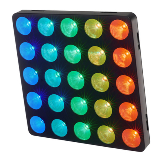
Features Features The LED blinder is particularly suitable for lighting applications in clubs and discotheques, on rock stages, and in theatres and musicals. Special features of the device: 25 RGBWW LEDs (10 W each), arranged in a 5×5 matrix Control via DMX (3 different modes) and via buttons and the display on the device 27 preprogrammed automatic shows LED matrix allows the display of letters and numbers via DMX Strobe effect... -
Page 14: Installation
Installation Installation Unpack and check carefully there is no transportation damage before using the unit. Keep the equipment packaging. To fully protect the product against vibration, dust and moisture during transportation or storage use the original packaging or your own packaging material suitable for transport or storage, respectively. - Page 15 Installation NOTICE! Risk of overheating and fire due to inadequate distance and bad ventilation! If the distance between the light source and the illuminated surface is too short or the device is badly ventilated, the device can overheat and cause fires. Make sure that illuminated surfaces are more than 2 m away.
- Page 16 Installation NOTICE! Data transfer errors due to improper wiring! If the DMX connections are wired incorrectly, this can cause errors during the data transfer. Do not connect the DMX input and output to audio devices, e.g. mixers or ampli‐ fiers. Use special DMX cables for the wiring instead of normal microphone cables.
-
Page 17: Starting Up
Starting up Starting up Create all connections while the device is off. Use the shortest possible high-quality cables for all connections. Take care when running the cables to prevent tripping hazards. Connections in DMX mode Connect the DMX input of the device to the DMX output of a DMX controller or another DMX device. - Page 18 Starting up Connections in master/slave When you configure a group of devices in master/slave mode, the first unit will control the mode other units for an automatic, sound-activated, synchronized show. This function is ideal when you want to start a show immediately. Connect the DMX output of the master device to the DMX input of the first slave device.
-
Page 19: Connections And Controls
Connections and controls Connections and controls ö ö & LED Matrix Blinder 5x5 RGB WW FUSE T2A250V Max: 6A ARTNET 1 ARTNET 2 ö ö Matrix Blinder 5x5 RGBWW Blinder... - Page 20 Connections and controls 1 Thread holes (M10), suitable for connecting elements 2 Safety cable eyelet 3 Bracket for suspension or set-up 4 Locking screws for the bracket 5 Display [Mode] | Activates the main menu and toggles between menu items. Closes an open submenu. [Setup] | Selects an option of the respective operating mode [Up] | Increases the displayed value by one [Down] | Decreases the displayed value by one...
-
Page 21: Operating
Operating Operating 7.1 Starting the device Connect the device to the power supply to start operation. After a few seconds, the display indicates that a reset is in progress. The device is then ready for use. The display shows the operating mode that was selected when the device was last powered off. -
Page 22: Dmx Address
Operating 7.2.1 DMX address Press [Mode] repeatedly until the display shows ‘DMX’ . Press [Setup] repeatedly until the display shows ‘Address’ . Use [Up] and [Down] to select a value between ‘001’ and ‘512’ to set the desired DMX address. Make sure that this number matches the configuration of your DMX controller. -
Page 23: Dmx Mode
Operating 7.2.2 DMX mode Press [Mode] repeatedly until the display shows ‘DMX’ . Press [Setup] repeatedly until the display shows ‘Channels’ . Use [Up] and [Down] to select one of the following DMX operating modes: ‘4-CH’ (four channels) ‘9-CH’ (nine channels) ‘100-CH’... -
Page 24: Network Settings (Artnet/Sacn)
Operating 7.2.3 Network settings (ARTNET/sACN) In this menu you determine the network settings. Press [Mode] repeatedly until the display shows ‘ARTNET/sACN’ . Press [Setup] repeatedly until the display shows the desired submenu. Adjust the value using [Up] and [Down]. Menu level 2 Function ‘IP Address’... -
Page 25: Operating Mode 'Slave
Operating 7.2.4 Operating mode ‘Slave’ Press [Mode] repeatedly until the display shows ‘Slave’ . Use [Setup] to select between ‘Yes’ (operating mode ‘Slave’ activated) and ‘No’ (oper‐ ating mode ‘Slave’ deactivated). ð When this operating mode is activated, the device works as slave. With correct cabling, it behaves exactly like the controlling master device. -
Page 26: Operating Mode 'Preprogrammed Automatic Show
Operating 7.2.6 Operating mode ‘Preprogrammed automatic show’ This operating mode can only be activated when the device is operating in stand alone mode or as master in a master / slave combination. This setting is only relevant if the device is not controlled via DMX. -
Page 27: Dimmer
Operating 7.2.7 Dimmer This operating mode can only be activated when the device is operating in stand alone mode or as master in a master / slave combination. This setting is only relevant if the device is not controlled via DMX. Press [Mode] repeatedly until the display shows ‘Dimmer’... -
Page 28: Sound Control
Operating 7.2.8 Sound control This operating mode can only be activated when the device is operating in stand alone mode or as master in a master / slave combination. This setting is only relevant if the device is not controlled via DMX. Press [Mode] repeatedly until the display shows ‘Sound’... -
Page 29: System Settings
Operating 7.2.9 System settings 7.2.9.1 Dimmer curve Press [Mode] repeatedly until the display shows ‘Settings’ . Press [Setup] repeatedly until the display shows ‘Curves Select’ . Use [Up] and [Down] to select one of the four dimmer curves ‘1’ to ‘4’ . Menu level 3 Function ‘Linear’... - Page 30 Operating 7.2.9.2 Dimmer response Press [Mode] repeatedly until the display shows ‘Settings’ . Press [Setup] repeatedly until the display shows ‘Dimmer Speed’ . Press [Up] and [Down] to select the desired dimmer response. Menu level 3 Function ‘Fast’ Fast change of light intensity ‘Smooth’...
- Page 31 Operating 7.2.9.3 Pointing the light beam Press [Mode] repeatedly until the display shows ‘Settings’ . Press [Setup] repeatedly until the display shows ‘Pixel Dir’ . Press [Up] and [Down] to select the desired light beam pointing. Menu level 3 Function ‘normal’...
- Page 32 Operating 7.2.9.4 Behaviour on DMX control failure Press [Mode] repeatedly until the display shows ‘Settings’ . Press [Mode] repeatedly until the display shows ‘DMX Fail’ . Use [Up] and [Down] to select between ‘Off’ , ‘Hold’ , ‘Dimmer’ , and ‘Program’ to make the setting to be used when the DMX controller fails.
- Page 33 Operating 7.2.9.5 DMX synchronisation The DMX synchronization allows to synchronize the settings of the device with other DMX controlled devices. Press [Mode] repeatedly until the display shows ‘Settings’ . Press [Setup] repeatedly until the display shows ‘Dmx Sync’ . Use [Up] and [Down] to select between ‘On’ (DMX synchronisation on) and ‘Off’ (DMX synchronisation off).
-
Page 34: System Information
Operating 7.2.10 System information 7.2.10.1 Firmware version Press [Mode] repeatedly until the display shows ‘Information’ . Press [Setup] repeatedly until the display shows ‘Version’ . ð The display shows the current firmware version. 7.2.10.2 Device temperature Press [Mode] repeatedly until the display shows ‘Information’ . Press [Setup] repeatedly until the display shows ‘Temperature’... - Page 35 Operating 7.2.10.3 Operating time Press [Mode] repeatedly until the display shows ‘Information’ . Press [Setup] repeatedly until the display shows ‘Work Time’ . ð The display shows the time during which the device has been connected to the power supply. To reset the operating time, press and hold [Setup] for five seconds and use [Up] and [Down] to enter the password 0088.
- Page 36 Operating 7.2.10.4 RDM function (Remote Device Management) The device provides an RDM function and is compatible to DMX512 standard. It is possible to recognize every device with RDM from the UID code. Press [Mode] repeatedly until the display shows ‘Information’ . Press [Setup] repeatedly until the display shows ‘UID’...
- Page 37 Operating Parameter ID Detection com‐ Sent command Received mand command SENSOR_DEFINITION SENSOR_VALUE DMX_PERSONALITY DMX_PERSONALITY_DESCRIPTION RESET_DEVICE FACTORY_DEFAULTS Matrix Blinder 5x5 RGBWW Blinder...
-
Page 38: Menu Overview
Operating 7.3 Menu overview ARTNET/sACN Slave AUTO Programm Dimmer Address IP Address Mode Subnet Mask Channels 4-CH Color Green 9-CH 100-CH Sub-Net Speed Blue Universe Strobe White sACN-Uni 63999 Matrix Blinder 5x5 RGBWW Blinder... - Page 39 Operating Sound Settings Information Mode Curves Select Version Temperature Work Time Fast Sensitivity Dimmer Speed Smooth Halogen Pixel Dir normal invert Dmx Fail Hold Dimmer Program Dmx Sync Lock Factory Matrix Blinder 5x5 RGBWW Blinder...
-
Page 40: Functions In 4-Channel Dmx Mode
Operating 7.4 Functions in 4-channel DMX mode Channel Value Function 0…255 Intensity Red (0 % to 100 %) 0…255 Intensity green (0 % to 100 %) 0…255 Intensity blue (0 % to 100 %) 0…255 Intensity white (0 % to 100 %) Matrix Blinder 5x5 RGBWW Blinder... -
Page 41: Functions In 9-Channel Dmx Mode
Operating 7.5 Functions in 9-channel DMX mode Channel Value Function 0…255 Intensity Red (0 % to 100 %) 0…255 Intensity green (0 % to 100 %) 0…255 Intensity blue (0 % to 100 %) 0…255 Intensity white (0 % to 100 %) Strobe effect 000…010 No function... - Page 42 Operating Channel Value Function 046…051 Number ‘5’ 052…057 Number ‘6’ 058…063 Number ‘7’ 064…069 Number ‘8’ 070…075 Number ‘9’ Selection of the displayed letter 076…081 Letter ‘A’ 082…087 Letter ‘B’ 088…093 Letter ‘C’ 094…099 Letter ‘D’ 100…105 Letter ‘E’ 106…111 Letter ‘F’...
- Page 43 Operating Channel Value Function 136…141 Letter ‘K’ 142…147 Letter ‘L’ 148…153 Letter ‘M’ 154…159 Letter ‘N’ 160…165 Letter ‘O’ 166…171 Letter ‘P’ 172…177 Letter ‘Q’ 178…183 Letter ‘R’ 184…189 Letter ‘S’ 190…195 Letter ‘T’ 196…201 Letter ‘U’ 202…207 Letter ‘V’ 208…213 Letter ‘W’...
- Page 44 Operating Channel Value Function Preprogrammed automatic show 000…015 No function 016…055 Preprogrammed automatic show no. 1 056…095 Preprogrammed automatic show no. 2 096…135 Preprogrammed automatic show no. 3 136…175 Preprogrammed automatic show no. 4 176…215 Preprogrammed automatic show no. 5 216…255 Preprogrammed automatic show no.
- Page 45 Operating Channel Value Function 052…060 Sound mode 5 061…069 Sound mode 6 070…078 Sound mode 7 079…087 Sound mode 8 088…096 Sound mode 9 097…105 Sound mode 10 106…114 Sound mode 11 115…123 Sound mode 12 124…132 Sound mode 13 133…141 Sound mode 14 142…150...
- Page 46 Operating Channel Value Function 196…204 Sound mode 21 205…213 Sound mode 22 214…222 Sound mode 23 223…231 Sound mode 24 232…240 Sound mode 25 241…255 Sound mode 26 Matrix Blinder 5x5 RGBWW Blinder...
-
Page 47: Functions In 100-Channel Dmx Mode
Operating 7.6 Functions in 100-channel DMX mode The figure alongside shows the numbering of the LEDs. Channel Value Function 0…255 Intensity red (0 % to 100 %), LED 1 0…255 Intensity Green (0 % to 100 %), LED 1 0…255 Intensity Blue (0 % to 100 %), LED 1 0…255 Intensity White (0 % to 100 %), LED 1... -
Page 48: Technical Specifications
Technical specifications Technical specifications Light source 25 × RGBWW LED, 10 W each 450 mm Optical properties Beam angle 38° Diameter of lenses 6.3 cm Control DMX, ArtNet, buttons and display on the device Number of DMX channels 4, 9 or 100 Input connections Power supply Lockable input socket... - Page 49 Technical specifications Fuse 5 mm × 20 mm, 2 A, 250 V, slow blow International Protection IP20 Rating Mounting options Hanging, standing M6 M10 threaded holes, suitable for connecting elements Dimensions (W × H × D) 450 mm × 450 mm × 115 mm Weight 10.2 kg Ambient conditions...
-
Page 50: Plug And Connection Assignments
Plug and connection assignments Plug and connection assignments Introduction This chapter will help you select the right cables and plugs to connect your valuable equip‐ ment so that a perfect light experience is guaranteed. Please take our tips, because especially in ‘Sound & Light’ caution is indicated: Even if a plug fits into a socket, the result of an incorrect connection may be a destroyed DMX controller, a short circuit or ‘just’... -
Page 51: Troubleshooting
Troubleshooting Troubleshooting NOTICE! Data transfer errors due to improper wiring! If the DMX connections are wired incorrectly, this can cause errors during the data transfer. Do not connect the DMX input and output to audio devices, e.g. mixers or ampli‐ fiers. - Page 52 4. Check whether the DMX cables run near or parallel to high- voltage cables that may cause damage or interference to a DMX interface circuit. If the procedures recommended above do not succeed, please contact our Service Center. You can find the contact information at www.thomann.de. Matrix Blinder 5x5 RGBWW Blinder...
-
Page 53: Cleaning
Cleaning Cleaning Optical lenses Clean the optical lenses, that are accessible from the outside, regularly in order to optimize the light output. The frequency of cleaning depends on the operating environment: wet, smoky or particularly dirty surroundings can cause more accumulation of dirt on the optics of the device. -
Page 54: Protecting The Environment
Protecting the environment Protecting the environment Disposal of the packing material Environmentally friendly materials have been chosen for the packaging. These materials can be sent for normal recycling. Ensure that plastic bags, packaging, etc. are disposed of in the proper manner. Do not dispose of these materials with your normal household waste, but make sure that they are collected for recycling. - Page 55 When disposing of the device, comply with the rules and regulations that apply in your country. You can also return your old device to Thomann GmbH at no charge. Check the current conditions on www.thomann.de.
- Page 56 Notes Matrix Blinder 5x5 RGBWW Blinder...
- Page 57 Notes Matrix Blinder 5x5 RGBWW Blinder...
- Page 58 Notes Matrix Blinder 5x5 RGBWW Blinder...
- Page 60 Musikhaus Thomann · Hans-Thomann-Straße 1 · 96138 Burgebrach · Germany · www.thomann.de...
Need help?
Do you have a question about the StairVille Matrix Blinder 5x5 RGBWW and is the answer not in the manual?
Questions and answers