Table of Contents
Advertisement
Quick Links
Advertisement
Table of Contents
Troubleshooting

Related Manuals for Endress+Hauser Master Meter System


Summary of Contents for Endress+Hauser Master Meter System
- Page 1 Products Solutions Services BA02244D/06/EN/01.22-00 71561511 2022-04-04 Valid as of version 01.00.zz (Device firmware) Operating Instructions Master Meter System High-precision measurement in custody transfer applications thanks to regular proving with the Master Meter System from Endress+Hauser...
- Page 2 • The manufacturer reserves the right to modify technical data without prior notice. Your Endress+Hauser Sales Center will supply you with current information and updates to these instructions. Endress+Hauser...
-
Page 3: Table Of Contents
Master Meter System Table of contents Table of contents About this document ....5 Commissioning ....17 Document function . - Page 4 Table of contents Master Meter System 10.3 Spare parts ......52 10.4 Spare parts and services ....52 10.5 Disposal .
-
Page 5: About This Document
Master Meter System About this document About this document Document function These Operating Instructions contain all the information required in the various life cycle phases of the device: from product identification, incoming acceptance and storage, to installation, connection, operation and commissioning, through to troubleshooting, maintenance and disposal. -
Page 6: Tool Symbols
About this document Master Meter System Symbol Meaning Bluetooth Wireless data transmission between devices over a short distance. Light emitting diode is off. Light emitting diode is on. Light emitting diode is flashing. 1.2.4 Tool symbols Symbol Meaning Torx screwdriver... -
Page 7: Symbols In Graphics
• W@M Device Viewer (www.endress.com/deviceviewer): Enter the serial number from the nameplate • Endress+Hauser Operations App: Enter the serial number from the nameplate or scan the matrix code on the nameplate Detailed list of the individual documents incl. documentation code → 55... -
Page 8: Supplementary Device-Dependent Documentation
About this document Master Meter System 1.6.1 Supplementary device-dependent documentation Additional documents are supplied depending on the device version ordered: Always comply strictly with the instructions in the supplementary documentation. The supplementary documentation is an integral part of the device documentation. -
Page 9: Safety Instructions
System. The functionality described in this manual applies to users with the Operator authorization level. The HMI of the Master Meter System was designed for use with Proline Promass F/Q/X 300/500 Coriolis flowmeters as master meter. Any other use is regarded as improper use. -
Page 10: Operational Safety
Safety instructions Master Meter System If working on and with the system with wet hands: ‣ Due to the increased risk of electric shock, wear suitable gloves. Operational safety Risk of injury! ‣ Operate the system only if it is in proper technical condition, free from errors and faults. -
Page 11: Product Description
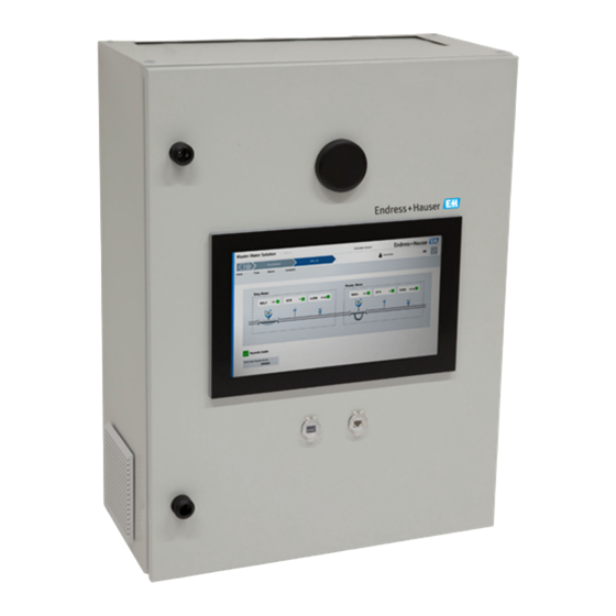
Master Meter System Product description Product description The main functions of the HMI of the MM System are to enable operation of the system, visualization of the test operation and also data management and troubleshooting. The HMI was designed to provide user-friendly, step-by-step procedures for safety operation. -
Page 12: Interfaces
Modifying the system Only appropriately trained and qualified staff are permitted to modify the system. Modifications to the hardware or software may be performed only by Endress+Hauser Service prior to implementing updates or upgrades. If you require further support, contact your local Endress+Hauser Sales Center. -
Page 13: Incoming Acceptance And Product
• Retain all accompanying documents. The system must not be put into operation if it has been established that the delivery is damaged. In this case, please contact your Endress+Hauser Sales Center. Return the system to Endress+Hauser in the original packaging where possible. -
Page 14: Storage And Transport
Storage and transport Master Meter System Storage and transport Storage conditions Observe the following notes for storage: ‣ Store in the original packaging to ensure protection from shock. ‣ Protect from direct sunlight to avoid unacceptably high surface temperatures. ‣... -
Page 15: Non-Ex Version
Master Meter System Installation 6.1.1 Non-Ex version 334 (13.2) 624 (24.6) 326 (12.8) 600 (23.6) 300 (11.8) 561 (22.1) A0048021 4 Dimensions in mm (in) 6.1.2 Ex Zone 1 version 430 (16.9) 311 (12.2) 405 (15.9) A0048022 5... -
Page 16: Ex Zone 2 Version
Installation Master Meter System 6.1.3 Ex Zone 2 version 311 (12.2) 600 (23.6) 561 (22.1) 300 (11.8) A0048023 6 Dimensions in mm (in) 6.1.4 Weight Version Number of lines Weight Non-Ex 48 kg (106 lb) 50 kg (110 lb) -
Page 17: Commissioning
Master Meter System Commissioning Commissioning Software update If an update is required for one of the following programs, this must be carried out first: • HMI • OPC • Flow computer app Wireless communication (can be used on a tablet PC) All process values from the flow computer, MM and DUT are linked via an industrial switch and transmitted to the tablet PC via an industrial, wireless router. -
Page 18: Operation
The status bar is located at the top of the screen and contains the following information: • System name • Customer name • System date, system time • Endress+Hauser logo (→ 7, 18) or system status (OK, warning, error; → 8, 18) A0048129 7... -
Page 19: Navigation Bar
Master Meter System Operation 8.2.2 Navigation bar The navigation bar is located at the top of the screen, directly below the status bar, and enables navigation between the individual screens. The current screen is displayed with a blue background. A0048131 User management User management is where the access rights for operation are organized. -
Page 20: Home" Screen
Operation Master Meter System "Home" screen Each time the tablet PC or panel PC is switched on or restarted, the HMI program is automatically loaded and the home screen then appears. The operator can navigate from here to the following main sections: •... -
Page 21: Prove Wizard
Master Meter System Operation A0048040 Prove Wizard 8.6.1 "Master Meter" screen The Prove Wizard is the main interface in the software where the operator can manage and perform proving operations in an organized manner. On the "Proving" screen, tap Prove Wizard. The "Master Meter" screen opens. A predefined MM device (→... - Page 22 Operation Master Meter System At each stage of the Prove Wizard, the Abort Wizard button is visible at the bottom of the screen to allow the operator to cancel the current wizard (→ 11, 22). If you tap this button, the system prompts the user to confirm the cancellation of the wizard.
-
Page 23: Duty Meter" Screen
Master Meter System Operation 8.6.2 "Duty Meter" screen Once the MM has been selected, tap Next Step. The "Duty Meter" screen opens. Up to 12 predefined Duty Meters (→ 12, 23) and the Free Select option (→ 13, 23, if enabled) are available to the operator. -
Page 24: Prove Setup" Screen
Operation Master Meter System 8.6.3 "Prove Setup" screen Once the Duty Meter has been selected, tap Next Step. The "Prove Setup" screen opens. Here the operator can select the "prove mode" required for the application and check the predefined settings under "Prove Mode", "Prove Method", "Meter Factor Limit Check" and "Other Prove Settings"... -
Page 25: Summary" Screen
Master Meter System Operation 8.6.4 "Summary" screen Once the settings have been confirmed, tap Next Step. The "Summary" screen opens. The system now provides the operator with a summary of the previously selected settings (→ 25). If there are red fields present, please wait a few seconds until the new selection has been synchronized with the MM flow computer and all fields are green. - Page 26 Operation Master Meter System A0048050 A0048052 Endress+Hauser...
-
Page 27: Prove Result" Screen
Master Meter System Operation 8.6.6 "Prove Result" screen Once the operation has been completed, tap Prove Result. The "Prove Result" screen opens. This is the final screen of the Prove Wizard. Tap Finish and the system will return to the home screen of the wizard. -
Page 28: Reports" Screen
Operation Master Meter System "Reports" screen In the "Proving" screen, tap Reports. The "Reports" screen opens. Here the operator can retrieve, display and export reports on previous operations. The individual report files are saved in .txt format and can be opened in the File Explorer and exported to an external drive by following the instructions on the screen. -
Page 29: Overview Report
Master Meter System Operation 8.8.1 Overview Report The following is an example of an "Overview Report" in the current software version: A0048095 Endress+Hauser... -
Page 30: Run Report
Operation Master Meter System 8.8.2 Run Report The following is an example of a "Run Report" in the current software version: A0048096 Endress+Hauser... -
Page 31: Diagnostics" Screen
Master Meter System Operation "Diagnostics" screen On the "Home" screen, tap Diagnostics. The "Diagnostics" screen opens. From here, the operator can navigate to the following five subsections: • Alarms • Alarm History • Process Data • I/O Diagnostics • Modbus Diagnostics A0048055 If an alarm occurs, a red exclamation mark appears in the "Diagnostics"... -
Page 32: Alarms" Screen
Operation Master Meter System 8.9.1 "Alarms" screen On the "Diagnostics" screen, tap Alarms. The "Alarms" screen opens. All active alarms are displayed in the form of a list (→ 32). Tap the Acknowledge All button to change the status of the alarms from "Active" to "Inactive" and to change the system status from "Warning"... -
Page 33: Alarm History" Screen
Master Meter System Operation 8.9.2 "Alarm History" screen On the "Diagnostics" screen, tap Alarm History. The "Alarm History" screen opens. Previous alarms of any status are displayed in the form of a list and can be filtered according to the operator' s requirements. -
Page 34: Modbus Diagnostics" Screen
Operation Master Meter System A0048062 8.9.5 "Modbus Diagnostics" screen On the "Diagnostics" screen, tap Modbus Diagnostics. The "Modbus Diagnostics" screen opens. The "Modbus Diagnostics" screen shows the process parameters transmitted by the relevant Master and Duty Meter via Modbus, once Modbus communication has been successfully established. -
Page 35: System" Screen
Master Meter System Operation 8.10 "System" screen On the "Home" screen, tap System. The "System" screen opens. The operator can navigate from here to the following seven subsections: • Language • Settings • Information • Software • Alarm limits • System settings •... -
Page 36: Language" Screen
Operation Master Meter System 8.10.1 "Language" screen On the "System" screen, tap Language. The "Language" screen opens. The operator can switch freely between English and German as the menu language. The default system language at startup is English. A0048066 8.10.2 "Prover Settings"... - Page 37 Master Meter System Operation A0048067 "Proving" tab The operator can define a range of proving settings: • Default Prove Mode Settings: • Maximum Number of Runs • Required Good Runs • Repeatability Limit • Default Prove Method settings: • Pulse Counts •...
- Page 38 Operation Master Meter System "Master Meter" tab The operator can configure the following parameters for the MM: • Serial Number • Tagname • Manufacturer • Meter Type • Meter Size • K-Factor (in pulses/t) The operator can also enable or disable the "Flow Rate Deviation Check" and define the following settings: •...
- Page 39 Master Meter System Operation A0048070 "Units" tab The operator can configure the units for the following terms: • MM Mass K-Factor • DUT Mass K-Factor • Flow Time Unit • Temperature • Pressure • Density • Line Pressure • Vapor Pressure...
- Page 40 Operation Master Meter System "I/O Config." tab The operator can configure the following parameters for the field instrument: • Master Meter Temperature • Master Meter Pressure • Duty Meter Temperature • Duty Meter Pressure A0048073 "Flow Stability" tab The operator can enable or disable the "Proving Stability" and define the following settings: •...
-
Page 41: Information" Screen
Master Meter System Operation 8.10.3 "Information" screen On the "System" screen, tap Information. The "Information" screen opens. This is where the manufacturer' s contact details are provided, which the operator can use if assistance is required. A0048076 8.10.4 "Software" screen On the "System"... -
Page 42: System Settings" Screen
Operation Master Meter System A0048078 8.10.6 "System Settings" screen On the "System" screen, tap System Settings. The "System Settings" screen opens. The operator can navigate from here to the six tabs: • User Management • HMI • File Path • IP Addresses •... - Page 43 Master Meter System Operation "HMI" tab The operator can determine whether the alarm banner should be shown on the home screen and can select the display format for the system date and time. A0048080 "File Path" tab The operator can select the file path for "Metering Data" and "Settings Import/Export".
- Page 44 Operation Master Meter System "IP Addresses" tab The operator can define or modify the IP address for the flow computer(s). A0048082 "Visualization" tab The operator can select the MM type to be shown on the visualization screen. A0048083 Endress+Hauser...
-
Page 45: Exit" Screen
Master Meter System Operation "Import/Export" tab The operator can import or export the configuration file. Only users with the highest "EH" access authorization level are permitted to import configurations. A0048085 8.10.7 "Exit" screen On the "System" screen, tap Exit. The "Exit" screen opens. -
Page 46: Users" Screen
Operation Master Meter System The operator can select the MM used to display the real-time measured values of various field devices on the line connected to the Duty Meter (→ 14, 46). The Duty Meter can be configured by tapping the Configure DUT button (→ 15, 46). -
Page 47: User Management
Master Meter System Operation A0048092 16 Users 8.12.1 User Management User management comprises three customer levels and an EH level: • Operator (basic operation) • Supervisor (plus advanced operation, customer settings, operator management) • Administrator (plus supervisor management) • EH (plus system parameter settings) 8.12.2... -
Page 48: Diagnostics And Troubleshooting
The flow computer has been restarted. This is normal behavior following an intended System Restart restart. In any other case, contact Endress+Hauser. Flow Computer 1 MM Modbus RTU communication between flow Check wiring of Modbus RTU (RS-485) cables. Comms Fail computer and Promass MM has failed. - Page 49 Flow Computer 1 RAM An internal flow computer error has occurred. Restart flow computer. Fail If error persists, contact Endress+Hauser. Flow Computer 1 RTC An internal flow computer error has occurred. Restart flow computer. Error If error persists, contact Endress+Hauser.
- Page 50 The flow computer has been restarted. This is normal behavior following an intended System Restart restart. In any other case, contact Endress+Hauser. Flow Computer 2 MM Modbus RTU communication between flow Check wiring of Modbus RTU (RS-485) cables. Comms Fail computer and Promass MM has failed.
-
Page 51: Troubleshooting
Are there any beeping sounds? If the user wants to seek assistance, detailed descriptions are helpful for service staff. If the problem persists after the user has followed the instructions in this section, contact your local Endress+Hauser Sales Center. Endress+Hauser... -
Page 52: Maintenance And Repair
General information • Use only original spare parts. • Compliance with all applicable standards, regional/national laws and certificates is mandatory. • Repairs may be carried out only by Endress+Hauser service employees or by suitably trained customer staff. 10.2 Cabinet fan The filter mat of the cabinet fan must be checked periodically. -
Page 53: Technical Data
Master Meter System Technical data Technical data 11.1 System components Flow computer (Newflow NÅNO-311) A0048150 Ethernet switch (Moxa EDS-208) A0048151 Industrial 4G LTE Wi-Fi router (Teltonika RUT240) A0048152 Antenna (Teltonika Combo SISO Mobile) A0048153 Endress+Hauser... - Page 54 Technical data Master Meter System 15.6" Panel PC (Advantech PPC-3151W) A0048154 15.6" Panel PC (B&R PC 2200) A0048794 Automation PC (B&R PC 2200) A0048795 External display (ICOP PDX2-090T-8A) A0048796 Endress+Hauser...
-
Page 55: Power Supply
Master Meter System Technical data 11.2 Power supply MM cabinet 110 to 230 V AC at 50/60 Hz 11.3 Input/output 24 V DC pulse, Modbus RTU MM temperature Current signal 4 to 20 mA MM pressure Current signal 4 to 20 mA... -
Page 56: Index
Index Master Meter System Index Symbols "Alarm History" screen ......33 Flow computer ......16 "Alarm Limits"... - Page 57 Master Meter System Index "Reports" screen ......28 Storage conditions ......14 Overview Report .
- Page 60 *71561511* 71561511 www.addresses.endress.com...
Need help?
Do you have a question about the Master Meter System and is the answer not in the manual?
Questions and answers