
Related Manuals for Danfoss ED-DT318B


Summary of Contents for Danfoss ED-DT318B
- Page 1 Installation and Operation Guide ED-DT318B Drive Train Systems with Traction Control Converter and Machine with 2 Speed Transmission Revision D URL/www.danfoss.com Classified as Business...
-
Page 2: Table Of Contents
TCU to MCU Interface Cable ................................. 37 Drivetrain Interface Connector ..............................37 DT2 Diagnostic Connector ................................43 Liquid Cooling MCU and Motor ..............................46 Coolant Loop Requirements ................................. 46 BC353060341319en-000101 Revision D © Danfoss | November 2020 | i Classified as Business... - Page 3 Controller Vibration Testing ............................... 152 9.1.1 SAE J1455 Vibration Test ................................152 9.1.2 GB/T 18488.1-2015 Vibration Test ............................153 Appendix B: Vehicle responses to Danfoss Power Solutions’ CAN Status Messages ........... 155 BC353060341319en-000101 Revision D © Danfoss | November 2020 | ii...
- Page 4 Installation and Operation Guide ED-DT318B Drive Train Systems with Traction Control, Inverter/Controller, and Motor with 2 Speed Transmission 10.1 Vehicle responses to Danfoss Power Solutions’ CAN Status Messages ..............155 Appendix C: Glossary ..................................176 11.1 Abbreviations ....................................177 Appendix D: Safety Notices ................................. 178...
-
Page 5: List Of Figures
Figure 3.8: Connector Bracket ................................... 37 Figure 3.9: Drivetrain Interface Connector (connector 3) ....................... 39 Figure 3.10: Danfoss Power Solutions Specification for 2 lead twisted pair shielded wire ..........41 Figure 3.11: Drivetrain Interface Connector terminals and wire seals ..................42 Figure 3.12: Allowed VCU to TCU CAN Bus Configurations ...................... - Page 6 Figure 8.22 Mark Event Log with Today’s Date dialog box ......................151 Figure 9.1: Controller Axis Orientation ..............................152 Figure 9.2: SAE J1455 PSD Bobtail vertical Mid frame, Heavy-duty Truck Profile ............... 153 BC353060341319en-000101 Revision D © Danfoss | November 2020 | v Classified as Business...
- Page 7 Table 4.1: Liquid Cooling System Requirements..........................47 Table 5.1: Potential Limitations ................................. 50 Table 8.1: Components of a Danfoss Power Solutions Motor Diagnostic Software Installation ........124 Table 8.2: Status Bar Communication Messages ..........................125 Table 8.3: Front Panel Group Descriptions ............................126 Table 8.4: Status Group Problems .................................
- Page 8 Decreased minimum air pressure requirement to implement shift Added Factory Diagnostic Message under TCU Status Message 2 2020/09/01 Jesse C. Loggins Update to reflect change of ownership to Danfoss BC353060341319en-000101 Revision D © Danfoss | November 2020 | vii Classified as Business...
-
Page 9: Introduction
This manual also provides an overview of the CAN interface of a Danfoss Power Solutions Motor Control Unit (MCU) coupled to an Eaton 2 speed transmission with a Transmission Control Unit (TCU). It includes details of the CAN message layout and addressing schemes for command, feedback, and status messages. -
Page 10: About This Guide
This manual utilizes textual explanations, diagrams, photographs, computer-aided design (CAD) renderings, and interface control drawings (ICDs) to guide the user through installation and operation. The latest ICD drawings for the PowerPhase DT2 system are available by contacting Danfoss Power Solutions. ® This manual is organized as follows: (1) •... -
Page 11: Control Units
High voltage components are identified by labels. Do not remove, open, take apart, or modify these components. High voltage cable or wiring has an orange covering. Do not probe, tamper with, cut, or modify high voltage cable or wiring. BC353060341319en-000101 Revision D © Danfoss | November 2020 | 10 Classified as Business... -
Page 12: Packaging And Disassembly
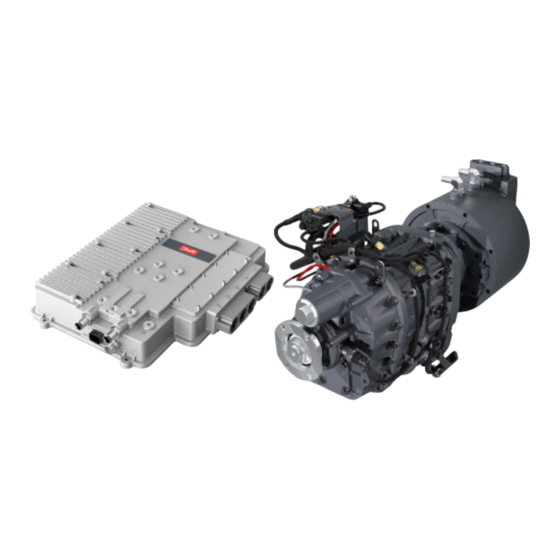
High Voltage DC battery. The system overview block diagram is shown below. BC353060341319en-000101 Revision D © Danfoss | November 2020 | 11 Classified as Business... -
Page 13: Figure 1.1: Block Diagram Of The Total System
(2.5 meters if not otherwise specified). D. Phase Cable — Included as part of the motor. Danfoss Power Solutions supplies the Phase Cable. The cable length is defined as part of the purchase order (2 meters if not otherwise specified). -
Page 14: Vehicle Control Unit
It is the user’s responsibility to determine and control the Danfoss Power Solutions system properly. • The user is responsible for integrating the Danfoss Power Solutions system into the vehicle and must implement any regulatory requirements to ensure compliance. •... -
Page 15: Installation
2.2.1 General Notes The controller may be mounted in any orientation. Danfoss Power Solutions advises that the cable entry points are NOT located on the top of the assembly, to avoid fluids wicking into the controller via the signal cable or user interface cable. -
Page 16: Vibration Considerations
2.2.4 Preparing the Coolant Loop for MCU and Motor Danfoss Power Solutions requires that the controller be the first component in the coolant loop. The controller coolant ports function as either inlet or outlet. The performance of the system is not impacted by which controller coolant port is used for inlet or outlet. -
Page 17: Routing The Tcu To Mcu Interface Cable
DT2 system can be found on the ICD drawing. Please ® discuss any other methods with Danfoss Power Solutions Engineering before implementing. 2.3.1 Connection of the driveline to the transmission output flange The output flange (mounts to transmission) is XS type, ISO 8667 cross serrated. The functional limiting torque of the output flange is 14 kNm. -
Page 18: Mounting The Motor/Transmission Into The Vehicle
The torque specification for M10x1.5 nuts is 60-70 Nm. Figure 2.1: Left Side – attachment points for bell housing & transmission mounting brackets. BC353060341319en-000101 Revision D © Danfoss | November 2020 | 17 Classified as Business... -
Page 19: Figure 2.2: Right Side - Attachment Points For Bell Housing & Transmission Mounting Brackets
Drive Train Systems with Traction Control, Inverter/Controller, and Motor with 2 Speed Transmission Figure 2.2: Right Side – attachment points for bell housing & transmission mounting brackets. Figure 2.3: Approved location of vibration isolators. BC353060341319en-000101 Revision D © Danfoss | November 2020 | 18 Classified as Business... -
Page 20: Overall Clearance Recommendation
The minimum distance from the isolator to the centerline of the transmission output shaft is 200mm; refer to Figure 2.3 for recommended location of isolators. The Danfoss Power Solutions recommended isolator is Hutchison 22003, 11, 12 or 13 and should be sized based on customer requirements. The customer should contact Hutchinson, Inc. -
Page 21: Motor Coolant Connections
In locations not covered by www.roadranger.com (e.g.: China) and where Eaton PS-164 is not available, BASF 2979 is the Eaton approved alternative. In the Chinese market, the BASF product is available from: Dealer: 上海振威化工有限公司 (Shanghai Zhenwei Chemical Co., Ltd) BC353060341319en-000101 Revision D © Danfoss | November 2020 | 20 Classified as Business... -
Page 22: Figure 2.6: Proper Lubricant Level
High ambient temperature • Restricted air flow around transmission • High torque in low gear or reverse operation • High power PTO operation for extensive periods while stationary BC353060341319en-000101 Revision D © Danfoss | November 2020 | 21 Classified as Business... -
Page 23: Figure 2.7: Transmission Lubricant Drain
Remove and clean the oil strainer. Clean the strainer in kerosene (paraffin) or suitable solvent and dry thoroughly. Renew the washer and the O-ring if necessary. When refitting, tighten to the torque (40 to 47 Nm). BC353060341319en-000101 Revision D © Danfoss | November 2020 | 22 Classified as Business... -
Page 24: Transmission Oil Cooler
Depending on operation conditions and availability of sufficient air flow to provide cooling, the customer may find that the oil to air cooler is not needed (test in vehicle required). BC353060341319en-000101 Revision D © Danfoss | November 2020 | 23 Classified as Business... -
Page 25: Figure 2.8: Eaton Transmission Lubricant Ports
Figure 2.9: Lubricant Drain Port If an external cooler is required, the customer must supply Metric Straight Thread O-ring Port M22x1.5 X 22mm Deep fittings appropriate to the chosen cooler. BC353060341319en-000101 Revision D © Danfoss | November 2020 | 24 Classified as Business... -
Page 26: Eaton Recommended Coolers
Figure 2.11: Eaton 18025 cooler heat transfer based on 38° C (100° F) temperature differential Advantages • Adds no heat to engine • No potential of cooler failure affecting engine • No coolant hoses required BC353060341319en-000101 Revision D © Danfoss | November 2020 | 25 Classified as Business... -
Page 27: Figure 2.12: Eaton 5586750 Oil To Water Heat Exchanger
Figure 2.12: Eaton 5586750 oil to water heat exchanger Figure 2.13: Eaton 5586750 heat exchanger heat transfer Requirements • 19mm (¾ inch) I.D. cooler lines • 8 GPM system flow at 1500 RPM BC353060341319en-000101 Revision D © Danfoss | November 2020 | 26 Classified as Business... -
Page 28: Air Supply To The Transmission
Note: 6.35mm (1/4”) tube OD push-to-connect fitting is installed on valve. To use 6mm tube, customer must replace with compatible fitting for proper assembly. The vehicle manufacturer is responsible for the air supply and the connections to the transmission BC353060341319en-000101 Revision D © Danfoss | November 2020 | 27 Classified as Business... -
Page 29: Electro-Magnetic Interference And Compatibility
Solutions cannot guarantee compliance with vehicle level testing that must occur. Some precautions can reduce the level of electromagnetic emissions and compatibility issues from the drive system once the ED-DT318B system is installed into a vehicle. They include, but are not limited to, the following suggestions: •... -
Page 30: Can And Rs232 Shielding
• For the CAN connection on the user interface connector, use a high quality, insulated, shielded, twisted pair cable (refer Danfoss Power Solutions p/n 14020-019, page 27. Do not allow the shield to touch the motor or controller housing. (See Section 6 for information on placement of termination resistors). -
Page 31: Electrical Connections
DANGER Failure to orient the power lug connections correctly can cause short to chassis. BC353060341319en-000101 Revision D © Danfoss | November 2020 | 30 Classified as Business... -
Page 32: Phase Cables (3 Phase Ac Cables)
3.1. They are the block of 3 cables on the left side of the diagram. Before connecting the phase cables, remove the termination cover shown in Figure 3.4. BC353060341319en-000101 Revision D © Danfoss | November 2020 | 31 Classified as Business... -
Page 33: Dc Cables
Tighten to the indicated torque in the ICD drawing. At rated peak power of the ED-DT318B system at the nominal voltage (both stated in the specific product specification sheet available through Danfoss Power Solutions sales); the Danfoss Power Solutions controller can draw over 650 Amps from the traction battery. -
Page 34: Figure 3.3: Hvil Daisy Chain Routing Thrugh The Controller And Motor
For the DT2 system the MCU to TCU cable is provided and has a breakout on the TCU end with a two pin TE Deutsch connector for the user HVIL connection. The mating connector is provided in the ship kit, Danfoss... -
Page 35: Termination Cover Installation
When connecting the Phase cables and the DC cables, ensure that the O-Rings are installed on the cable housings before attaching to controller as shown in Figure 3.1. These O-Rings may be already attached the cable BC353060341319en-000101 Revision D © Danfoss | November 2020 | 34 Classified as Business... -
Page 36: Grounding Requirements
1.1) is the small shielded cable with a 17-pin Amphenol M23 style connector. Some of the wires in this cable are used for the rotor position signals. Others are used to send stator and rotor thermal information to the controller. Danfoss Power Solutions provides this cable as part of the PowerPhase DT2 system, but the customer is responsible for connecting the signal cable from the motor to the ®... -
Page 37: Figure 3.5: Signal Cable Connection - Insertion
Figure 3.7: Signal Cable Connection – Final Torque Torque the mated connector to 20-30 in lbs. This is about 2-3X the torque that can be achieved by hand. BC353060341319en-000101 Revision D © Danfoss | November 2020 | 36 Classified as Business... -
Page 38: Tcu To Mcu Interface Cable
Drivetrain Interface Connector: VCU CAN Leg A (pins 1, 2 & 3) and VCU CAN Leg B (pins 4, 5 & 6). Both should be used as they are provided to preserve the integrity of the daisy chain for that bus. If the user elects to place BC353060341319en-000101 Revision D © Danfoss | November 2020 | 37 Classified as Business... - Page 39 Table 3.1. Danfoss Power Solutions recommends that the 24 volt supply voltage be controlled by the VCU and that it be fused using an automotive rated 10 amp fuse between on the low voltage lines to the controller/invertor. Treat this low voltage 24V supply as you would the ignition source for a gasoline powered vehicle. The 24V line must be at least 14 gauge wire to avoid a voltage drop in the wire supplying LV to the controller.
-
Page 40: Figure 3.9: Drivetrain Interface Connector (Connector 3)
TCU/MCU RS232 Transmit TxD 98010-022 15010-084 16040-020 14020-019 Diag SW RS232 Receive RxD 98010-022 15010-084 16040-020 14020-019 Diag SW RS232 Shield 98010-022 15010-084 16040-020 14020-019 Diag SW BC353060341319en-000101 Revision D © Danfoss | November 2020 | 39 Classified as Business... - Page 41 15010-083 16040-019 14 AWG Vehicle Battery Note: The terminals and wires seals will be packaged in 3 different bags corresponding to the different wire sizes as defined. BC353060341319en-000101 Revision D © Danfoss | November 2020 | 40 Classified as Business...
-
Page 42: Figure 3.10: Danfoss Power Solutions Specification For 2 Lead Twisted Pair Shielded Wire
Installation and Operation Guide ED-DT318B Drive Train Systems with Traction Control, Inverter/Controller, and Motor with 2 Speed Transmission Figure 3.10: Danfoss Power Solutions Specification for 2 lead twisted pair shielded wire BC353060341319en-000101 Revision D © Danfoss | November 2020 | 41... -
Page 43: Figure 3.11: Drivetrain Interface Connector Terminals And Wire Seals
Installation and Operation Guide ED-DT318B Drive Train Systems with Traction Control, Inverter/Controller, and Motor with 2 Speed Transmission Figure 3.11: Drivetrain Interface Connector terminals and wire seals BC353060341319en-000101 Revision D © Danfoss | November 2020 | 42 Classified as Business... -
Page 44: Dt2 Diagnostic Connector
TCU to MCU CAN bus. Note that the wiring from the MCU to the TCU is provided by Danfoss Power Solutions via the TCU to MCU Interface Cable. The customer is responsible for the wiring from the Drivetrain Interface Connector to the Diagnostic Connector. -
Page 45: Table 3.2: Rs232 Communications Pinout
VCU CAN - 14020-019 2 or 5 RS232 Receive RxD 14020-019 24 V Battery positive – Vbatt (TCU) 18 AWG use of a 10A fuse is recommended BC353060341319en-000101 Revision D © Danfoss | November 2020 | 44 Classified as Business... -
Page 46: Figure 3.13: Tcu To Mcu Can Bus
Installation and Operation Guide ED-DT318B Drive Train Systems with Traction Control, Inverter/Controller, and Motor with 2 Speed Transmission Figure 3.13: TCU to MCU CAN bus BC353060341319en-000101 Revision D © Danfoss | November 2020 | 45 Classified as Business... -
Page 47: Liquid Cooling Mcu And Motor
The coolant loop for the transmission MUST be on a SEPARATE coolant loop than the CAUTION MCU and Motor. BC353060341319en-000101 Revision D © Danfoss | November 2020 | 46 Classified as Business... -
Page 48: Flow Rate Vs. Pressure Drop
Minimum Coolant Flow Rate 10 liters per minute (LPM) Coolant volume for the controller and motor can be found on the ICD drawing or by contacting Danfoss Power Solutions. A coolant flow rate of 10.0 liters per minute will have a pressure drop of approximately 8.5 kPa total from just the controller and motor. -
Page 49: Electric Vehicle System Operation
5 Electric Vehicle System Operation 5.1 Electric Vehicle System Overview The Danfoss Power Solutions system is the main drive component of an Electric Vehicle System. The major items are shown below. Figure 5.1: Block Diagram of Electric Vehicle Drive System The customer must supply the Vehicle Control Module. -
Page 50: Valid Control Modes Via Can
For example, if an Acceleration Limit of 150 RPM/sec is set and a full torque request is issued to the Danfoss Power Solutions controller while the motor is at rest, then the Danfoss Power Solutions controller could deliver up to full torque to get the motor spinning. -
Page 51: Safety Features
Drive Train Systems with Traction Control, Inverter/Controller, and Motor with 2 Speed Transmission 5.3 Safety Features The Danfoss Power Solutions motor system provides built-in features to minimize hazardous conditions such as over motor current, over/under battery voltage, or over motor speed, with configurable values. It also has features to protect against battery disconnect, conditions causing stall, and hardware failures. - Page 52 This control mode, called Forced Voltage Control, takes priority over any other limit. BC353060341319en-000101 Revision D © Danfoss | November 2020 | 51 Classified as Business...
-
Page 53: Forced Voltage Control
Configuration. Note that if the regen switch is open then it will control the voltage to a higher value. This control mode is only allowed to use 10% of the motoring and regeneration capabilities of the Danfoss Power Solutions motor. The mode releases control within 128 milliseconds if conditions indicate that the battery is still connected. -
Page 54: Vehicle Responses To Danfoss Power Solutions Can Status Messages
The Vehicle Control Unit/Module will need to determine the appropriate actions to these messages. Danfoss Power Solutions is providing the status and error messages so that appropriate actions are taken at the vehicle level. Danfoss Power Solutions assumes no liability if the vehicle does not respond to our status and error messages. -
Page 55: Communications
TCU configuration data. The MCU configuration is updated via the RS232 port documented below. TCU to MCU CAN bus. Note that the wiring from the MCU to the TCU is provided by Danfoss Power Solutions via the TCU to MCU Interface Cable (Cable C in Figure 1.1). -
Page 56: Rs232 Communications
ED-DT318B Drive Train Systems with Traction Control, Inverter/Controller, and Motor with 2 Speed Transmission 6.3 RS232 Communications The Danfoss Power Solutions Motor Diagnostic Software (Section 8) communicates to the motor system through the RS232 communication pins (7, 15 & 8) of the DT2 Diagnostic Connector (Connector 4 in Figure 1.1). -
Page 57: Vcu To Tcu Can Bus
Newton meters millibars rpm: revolutions per minute rpm/s: revolutions per minute per second (rate of acceleration) ˚C: degrees Celsius VDC: Volts DC Amperes lsb: least significant bit BC353060341319en-000101 Revision D © Danfoss | November 2020 | 56 Classified as Business... -
Page 58: Boolean Values
(x) sender CAN address (ss) for CANOpen message 7.1.2 Boolean Values 0: False 1: True 7.1.3 Hexadecimal Values Hexadecimal values are denoted by a subscript of 16. E.g.: 255 = FF BC353060341319en-000101 Revision D © Danfoss | November 2020 | 57 Classified as Business... -
Page 59: Vcu To Tcu Command Messages
Speed Limit msB Speed Limit lsB Requested Torque msB Requested Torque 2nd msB Requested Torque 3rd msB Requested Torque lsB 7.2.1.1 TCU CAN Message Error dbc ref: TCUCmd1_TCU_CANMessageError lsb: BC353060341319en-000101 Revision D © Danfoss | November 2020 | 58 Classified as Business... - Page 60 During TCU startup, this value will be false until communication with the VCU and TCU has been established. The Transmission Mode should always be Neutral when TCU CAN Active is False. 7.2.1.3 TCU CAN Watchdog Timeout dbc ref: TCUCmd1_TCU_CANWatchdogTimeout lsb: BC353060341319en-000101 Revision D © Danfoss | November 2020 | 59 Classified as Business...
- Page 61 Watchdog Count conforms to the requirement, the TCU will report Traction Control Command Watchdog Timeout and will instruct the MCU to stop producing torque. 7.2.1.5 TCU Enable dbc ref: TCUCmd1_TCUEnable lsb: msb: BC353060341319en-000101 Revision D © Danfoss | November 2020 | 60 Classified as Business...
- Page 62 TCU is reporting MCU status to the VCU. Note 2: Transition to and from Reverse should only be allowed at extremely slow vehicle speeds (transmission output speed <50 rpm). BC353060341319en-000101 Revision D © Danfoss | November 2020 | 61 Classified as Business...
- Page 63 0 (Signed int) Scale Factor: Min Value: -6425.6 Max Value: 6425.5 Units: Description: The amount of torque the VCU is requesting the system deliver to the driveshaft. BC353060341319en-000101 Revision D © Danfoss | November 2020 | 62 Classified as Business...
- Page 64 The low gear ratio is 3.529:1, so the motor will attempt to produce the amount of torque equivalent to Requested Torque divided by 3.529. The multiplying effect of the gear ratio will result in the requested torque being supplied to the driveshaft. BC353060341319en-000101 Revision D © Danfoss | November 2020 | 63 Classified as Business...
-
Page 65: Tcu Command Message 2
Max Source Current Max Sink Current Driveshaft Speed msB Driveshaft Speed lsB 7.2.2.1 VCU Watchdog Counter 2 dbc ref: TCUCmd2_VCUWatchdogCounter_2 lsb: msb: Offset: Scale Factor: Min Value: BC353060341319en-000101 Revision D © Danfoss | November 2020 | 64 Classified as Business... - Page 66 Note 2: To avoid perturbations due to fluctuating limits, the command to the MCU will only be updated at a 1s interval. 7.2.2.3 Max Source Current dbc ref: TCUCmd2_MaxSourceCurrent lsb: msb: Offset: BC353060341319en-000101 Revision D © Danfoss | November 2020 | 65 Classified as Business...
- Page 67 Note4: To avoid perturbations due to fluctuating limits, the command to the MCU will only be updated at a 1s interval. 7.2.2.5 Driveshaft Speed dbc ref: TCUCmd2_DriveshaftSpeed lsb: msb: Offset: 0 (signed int) Scale Factor: BC353060341319en-000101 Revision D © Danfoss | November 2020 | 66 Classified as Business...
- Page 68 Description: The rotational speed of the driveshaft. If the Driveshaft Speed significantly diverges from the Transmission Output Speed, the TCU will report a Driveshaft Speed Mismatch Error. BC353060341319en-000101 Revision D © Danfoss | November 2020 | 67 Classified as Business...
-
Page 69: Tcu To Vcu Status Messages
MCU Major Version MCU Minor Version – msn MCU Minor Version – lsn MCU Sub Version 7.3.1.1 MCU System Type dbc ref: TCUStat1_MCUSystemType lsb: msb: Offset: Scale Factor: BC353060341319en-000101 Revision D © Danfoss | November 2020 | 68 Classified as Business... - Page 70 The VCU should monitor Watchdog Counter for any irregularities and react accordingly. 7.3.1.3 TCU System Type dbc ref: TCUStat1_TCUSystemType lsb: msb: Offset: Scale Factor: Min Value: 0 (“Unknown System Type”) Max Value: 65535 Units: Enumeration BC353060341319en-000101 Revision D © Danfoss | November 2020 | 69 Classified as Business...
- Page 71 Min Value: Max Value: Units: Integer Description: TCU Code Major Version Number. 7.3.1.6 TCU Minor Version dbc ref: TCUStat1_TCUMinorVersion lsb: msb: Offset: Scale Factor: Min Value: Max Value: BC353060341319en-000101 Revision D © Danfoss | November 2020 | 70 Classified as Business...
- Page 72 MCU Code Major Version Number. 7.3.1.9 MCU Minor Version dbc ref: TCUStat1_MCUMinorVersion lsb: msb: Offset: Scale Factor: Min Value: Max Value: Units: Integer Description: MCU Code Minor Version Number. BC353060341319en-000101 Revision D © Danfoss | November 2020 | 71 Classified as Business...
- Page 73 Drive Train Systems with Traction Control, Inverter/Controller, and Motor with 2 Speed Transmission 7.3.1.10 MCU Sub Version dbc ref: TCUStat1_MCUSubVersion lsb: msb: Offset: Scale Factor: Min Value: Max Value: Units: Integer Description: MCU Code Sub Version Number. BC353060341319en-000101 Revision D © Danfoss | November 2020 | 72 Classified as Business...
-
Page 74: Tcu Status Message 2
Temp Read Temp Read Temp Read Temp Error Watchdog Warning Limiting Error Error Error Error Timeout Regen Factory Diagnostic Message msb Type Error Factory Diagnostic Message lsb BC353060341319en-000101 Revision D © Danfoss | November 2020 | 73 Classified as Business... - Page 75 Control Command. Operational conditions may delay or prevent a mode change. 7.3.2.2 Selected Gear dbc ref: TCUStat2_SelectedGear lsb: msb: Offset: Scale Factor: Min Value: Max Value: Units: Enumeration Description: The currently selected gear. 0: Neutral 1: Low BC353060341319en-000101 Revision D © Danfoss | November 2020 | 74 Classified as Business...
- Page 76 False Gear shift to Low gear is not in progress 7.3.2.5 Upshift Failed dbc ref: TCUStat2_UpshiftFailed lsb: msb: Offset: Scale Factor: Min Value: Max Value: Units: Boolean BC353060341319en-000101 Revision D © Danfoss | November 2020 | 75 Classified as Business...
- Page 77 Note 3: The system will hold the current gear once it has encountered a downshift fail irrespective of the commanded transmission mode. 7.3.2.7 Slow Upshift dbc ref: TCUStat2_SlowUpshift lsb: msb: Offset: BC353060341319en-000101 Revision D © Danfoss | November 2020 | 76 Classified as Business...
- Page 78 Once gear shifting is disabled, it will not be reenabled until the entire system has been power cycled. Warning: the system should never be power cycled while the vehicle is in motion. 7.3.2.10 Max Shift Speed Delta Exceeded dbc ref: TCUStat2_MaxShiftSpeedDeltaExceeded BC353060341319en-000101 Revision D © Danfoss | November 2020 | 77 Classified as Business...
- Page 79 Shift Disabled will be set to True. The ability to shift to Neutral will not be affected. 7.3.2.12 Forced Gear Engagement Torque dbc ref: TCUStat2_ForcedGearEngagementTorque lsb: msb: Offset: Scale Factor: Min Value: Max Value: BC353060341319en-000101 Revision D © Danfoss | November 2020 | 78 Classified as Business...
- Page 80 False The difference between the Transmission Output Speed reported by the Transmission Speed Sensor and the Driveshaft Speed reported by the VCU is within the nominal tolerances. BC353060341319en-000101 Revision D © Danfoss | November 2020 | 79 Classified as Business...
- Page 81 TCU has timed-out waiting for status from the MCU. False TCU has received a status message from the MCU within the allotted time. 7.3.2.17 MCU Watchdog Error dbc ref: TCUStat2_MCUWatchdogError lsb: msb: Offset: Scale Factor: BC353060341319en-000101 Revision D © Danfoss | November 2020 | 80 Classified as Business...
- Page 82 The MCU has not received a TCU Command Message 1 message within the last second. False The MCU has received a TCU Command Message 1 message within the last second. BC353060341319en-000101 Revision D © Danfoss | November 2020 | 81 Classified as Business...
- Page 83 This bit will be True at startup. Once this bit is set to True, it will be held True until TCU Command Message 2 Error is set to False. 7.3.2.22 Transmission Temperature Warning dbc ref: TCUStat2_TransmissionTemperatureWarning BC353060341319en-000101 Revision D © Danfoss | November 2020 | 82 Classified as Business...
- Page 84 Offset: Scale Factor: Min Value: Max Value: Units: Boolean Description: True The TCU is limiting the maximum torque allowed due to excessive transmission lubricant temperature. BC353060341319en-000101 Revision D © Danfoss | November 2020 | 83 Classified as Business...
- Page 85 The MCU Inverter temperature sensor is working properly. 7.3.2.27 MCU Stator Temperature Read Error dbc ref: TCUStat2_MCUStatorTemperatureReadError lsb: msb: Offset: Scale Factor: Min Value: Max Value: Units: Boolean BC353060341319en-000101 Revision D © Danfoss | November 2020 | 84 Classified as Business...
- Page 86 The default setting for the MCU is new style regen. The TCU is designed to operate with New Style Regen, therefore the TCU will not operate if the system is in Old Style Regen. 7.3.2.30 Factory Diagnostic Message dbc ref: TCUStat2_FTYDiagnosticMessage lsb: msb: Offset: BC353060341319en-000101 Revision D © Danfoss | November 2020 | 85 Classified as Business...
- Page 87 Otherwise: Power Switches Off will correspond to the following messages in the Event Log (See the Danfoss Power Solutions User Manual for information on the Event Log). • Phase Driver Fault • Iq Noise too big •...
- Page 88 When this occurs, the MCU will enter the open loop mode of operation and severely limits the amount of torque the motor will produce. 7.3.2.33 MCU Bad Switch dbc ref: TCUStat2_MCUBadSwitch lsb: msb: Offset: Scale Factor: Min Value: Max Value: BC353060341319en-000101 Revision D © Danfoss | November 2020 | 87 Classified as Business...
- Page 89 When this occurs, the MCU will enter the open loop mode of operation and severely limits the amount of torque the motor will produce. 7.3.2.36 MCU Stall Condition Active dbc ref: TCUStat2_MCUStallConditionActive lsb: BC353060341319en-000101 Revision D © Danfoss | November 2020 | 88 Classified as Business...
- Page 90 7.3.2.38 MCU Turbo Mode dbc ref: TCUStat2_MCUTurboMode lsb: msb: Offset: Scale Factor: BC353060341319en-000101 Revision D © Danfoss | November 2020 | 89 Classified as Business...
- Page 91 FOC is the most common mode of operation for DC electric motors. The MCU uses this mode of operation at lower motor speeds. At higher motor speeds, the MCU uses a Danfoss Power Solutions proprietary algorithm known as Turbo Mode.
- Page 92 Min Value: Max Value: Units: Enumeration Description: The motor’s direction of rotation. 0: Reverse 1: Forward 7.3.2.43 MCU System Disabled In Motion dbc ref: TCUStat2_MCUSystemDisabledInMotion lsb: msb: BC353060341319en-000101 Revision D © Danfoss | November 2020 | 91 Classified as Business...
- Page 93 Speed value in the Traction Control Command. 7.3.2.45 MCU Forced Voltage Control dbc ref: TCUStat2_MCUForcedVoltageControl lsb: msb: Offset: Scale Factor: Min Value: Max Value: Units: Boolean BC353060341319en-000101 Revision D © Danfoss | November 2020 | 92 Classified as Business...
- Page 94 In this case, the MCU switches to Voltage Control Mode in an attempt to reduce the bus voltage. However, this mode is severely power limited to prevent a runaway vehicle condition. BC353060341319en-000101 Revision D © Danfoss | November 2020 | 93 Classified as Business...
-
Page 95: Tcu Status Message 3
MCU Over MCU Not Phase MCU Not Phase Enabled Advance Current Current Enabled Advance Current Current History History History History Transmission Output Speed msB Transmission Output Speed lsB BC353060341319en-000101 Revision D © Danfoss | November 2020 | 94 Classified as Business... - Page 96 MCU Inverter Fault has been set to True at some point since the last time MCU power was cycled. False MCU Inverter Fault has not been set to True at any point since the last time MCU power was cycled. BC353060341319en-000101 Revision D © Danfoss | November 2020 | 95 Classified as Business...
- Page 97 MCU Inverter Fault Latched has not been set to True at any point since the last time MCU power was cycled. 7.3.3.5 MCU Limp Home Mode dbc ref: TCUStat3_MCULimpHomeMode lsb: msb: Offset: Scale Factor: Min Value: Max Value: Units: Boolean BC353060341319en-000101 Revision D © Danfoss | November 2020 | 96 Classified as Business...
- Page 98 The torque delivered will be limited by the Limp Home Percentage, which is a percentage of the maximum torque possible at each speed and voltage point. See the Danfoss Power Solutions EC-C1200F + EM-PMI318B User Manual for more details.
- Page 99 Min Value: Max Value: Units: Boolean Description: True MCU Over Voltage Alarm has been set to True at some point since the last time MCU power was cycled. BC353060341319en-000101 Revision D © Danfoss | November 2020 | 98 Classified as Business...
- Page 100 MCU Over Speed Alarm has not been set to True at any point since the last time MCU power was cycled. 7.3.3.13 MCU Over Voltage Warning dbc ref: TCUStat3_MCUOverVoltageWarning lsb: msb: Offset: Scale Factor: BC353060341319en-000101 Revision D © Danfoss | November 2020 | 99 Classified as Business...
- Page 101 Power Solutions system is configured. False The High Voltage DC bus voltage is less than the maximum for which the Danfoss Power Solutions system is configured. If this condition is detected by the MCU, it will attempt to reduce the voltage by switching to the Forced Voltage Control mode and limiting the available regeneration torque.
- Page 102 7.3.3.18 MCU Inverter Over Temperature History dbc ref: TCUStat3_MCUInverterOverTemperatureHistory lsb: msb: Offset: Scale Factor: Min Value: BC353060341319en-000101 Revision D © Danfoss | November 2020 | 101 Classified as Business...
- Page 103 MCU Stator Over Temperature has been set to True at some point since the last time MCU power was cycled. False MCU Stator Over Temperature has not been set to True at any point since the last time MCU power was cycled. BC353060341319en-000101 Revision D © Danfoss | November 2020 | 102 Classified as Business...
- Page 104 MCU Rotor Over Temperature has not been set to True at any point since the last time MCU power was cycled. 7.3.3.23 MCU Under Voltage Warning dbc ref: TCUStat3_MCUUnderVoltageWarning lsb: msb: Offset: Scale Factor: Min Value: BC353060341319en-000101 Revision D © Danfoss | November 2020 | 103 Classified as Business...
- Page 105 Units: Boolean Description: True The High Voltage DC bus voltage is less than the minimum for which the Danfoss Power Solutions system is configured. False The High Voltage DC bus voltage is greater than the minimum for which the Danfoss Power Solutions system is configured.
- Page 106 Min Value: Max Value: Units: Boolean Description: True MCU Over Bus Current has been set to True at some point since the last time MCU power was cycled. BC353060341319en-000101 Revision D © Danfoss | November 2020 | 105 Classified as Business...
- Page 107 MCU Over Leg Current has not been set to True at any point since the last time MCU power was cycled. 7.3.3.31 MCU Not Enabled dbc ref: TCUStat3_MCUNotEnabled lsb: msb: Offset: Scale Factor: Min Value: Max Value: BC353060341319en-000101 Revision D © Danfoss | November 2020 | 106 Classified as Business...
- Page 108 BC353060341319en-000101 Revision D © Danfoss | November 2020 | 107 Classified as Business...
- Page 109 3.529 * Transmission Output Speed. When the transmission is in Neutral, there is no correlation between MCU Motor Speed and Transmission Output Speed. BC353060341319en-000101 Revision D © Danfoss | November 2020 | 108 Classified as Business...
-
Page 110: Tcu Status Message 4
VCU Torque Requested msB VCU Torque Requested 2nd msB VCU Torque Requested 3rd msB VCU Torque Requested lsB 7.3.4.1 Max Drive Torque Allowed dbc ref: TCUStat4_MaxDriveTorqueAllowed lsb: msb: Offset: BC353060341319en-000101 Revision D © Danfoss | November 2020 | 109 Classified as Business... - Page 111 The amount of torque the TCU is requesting the system to deliver to the driveshaft. This is the amount of torque the VCU requested in TCU Command Message 1 after it has been limited to the Max Drive and Max Regen Torque Allowed. BC353060341319en-000101 Revision D © Danfoss | November 2020 | 110 Classified as Business...
- Page 112 Note 1: This value will not exceed Max Drive Torque Allowed or the Max Regen Torque Allowed. Note 2: This value will be reported as 0 when the Transmission is in Neutral BC353060341319en-000101 Revision D © Danfoss | November 2020 | 111 Classified as Business...
-
Page 113: Tcu Status Message 5
MCU Desired Torque lsB MCU Torque msB MCU Torque lsB TCU Torque msB TCU Torque lsB 7.3.5.1 TCU Requested Torque dbc ref: TCUStat5_TCURequestedTorque lsb: msb: Offset: 0 (signed int) BC353060341319en-000101 Revision D © Danfoss | November 2020 | 112 Classified as Business... - Page 114 Note 3: This is the value reported by the MCU and is not corrected for the gear ratio. 7.3.5.3 MCU Torque dbc ref: TCUStat5_MCUTorque lsb: msb: Offset: 0 (signed int) Scale Factor: Min Value: -3212.8 Max Value: 3212.8 Units: BC353060341319en-000101 Revision D © Danfoss | November 2020 | 113 Classified as Business...
- Page 115 Note 1: Negative values denote regen torque. Note 2: This value is related to TCU Torque but it will be calculated based on the current gear ratio. BC353060341319en-000101 Revision D © Danfoss | November 2020 | 114 Classified as Business...
-
Page 116: Tcu Status Message 6
MCU Voltage lsB MCU Current msB MCU Current lsB MCU Leg Current msB MCU Leg Current lsB 7.3.6.1 MCU Acceleration Limit dbc ref: TCUStat6_MCUAccelerationLimit lsb: msb: Offset: BC353060341319en-000101 Revision D © Danfoss | November 2020 | 115 Classified as Business... - Page 117 The DC bus current being consumed (motoring) or produced (regeneration) by the MCU. Positive values indicate motoring, while negative values indicate regeneration operation. 7.3.6.4 MCU Leg Current dbc ref: TCUStat6_MCULegCurrent BC353060341319en-000101 Revision D © Danfoss | November 2020 | 116 Classified as Business...
- Page 118 MCU status report messages. It is representative of the currents driving the motor when it is motoring, or being produced by the motor when it is generating. BC353060341319en-000101 Revision D © Danfoss | November 2020 | 117 Classified as Business...
-
Page 119: Tcu Status Message 7
MCU Inverter Temperature MCU Stator Temperature MCU Rotor Temperature MCU Max Source Current MCU Max Sink Current 7.3.7.1 MCU Stall Safety Percentage dbc ref: TCUStat7_StallSafetyPercentage lsb: msb: Offset: BC353060341319en-000101 Revision D © Danfoss | November 2020 | 118 Classified as Business... - Page 120 Min Value: Max Value: Units: ˚C Description: The temperature of the MCU Inverter. Note: The MCU will limit motor torque to keep this temperature within acceptable limits. BC353060341319en-000101 Revision D © Danfoss | November 2020 | 119 Classified as Business...
- Page 121 Offset: Scale Factor: Min Value: Max Value: 1275 Units: Amps Description: The maximum current the MCU is allowed to source to the battery when in regen. BC353060341319en-000101 Revision D © Danfoss | November 2020 | 120 Classified as Business...
- Page 122 Offset: Scale Factor: Min Value: Max Value: 1275 Units: Amps Description: The maximum current the MCU is allowed to sink from the battery to drive the motor. BC353060341319en-000101 Revision D © Danfoss | November 2020 | 121 Classified as Business...
-
Page 123: Motor Diagnostic Software
Drive Train Systems with Traction Control, Inverter/Controller, and Motor with 2 Speed Transmission 8 Motor Diagnostic Software Danfoss Power Solutions provides diagnostic software with our systems. This software runs on Microsoft Windows XP and later, and provides an environment to monitor and record the motor system conditions. It also allows you to change motor system configuration settings. -
Page 124: Figure 8.2: Menu Bar
Group Figure 8.7: Control Group Figure 8.5: Status Group Figure 8.8: Electrical Group Figure 8.9: Data Acquisition (DAQ) Control Figure 8.10: Critical Group Figure 8.11: Status Bar BC353060341319en-000101 Revision D © Danfoss | November 2020 | 123 Classified as Business... -
Page 125: Setting Up The Software
Windows XP or later computer with a RS232 compliant COM port. A USB to RS232 Converter can be used to connect the COM port, but it must be installed before the Danfoss Power Solutions Motor Diagnostic Software. Table 8.1: Components of a Danfoss Power Solutions Motor Diagnostic Software Installation... -
Page 126: Status Bar
Section 8.5 of this manual. 8.2.1 Status Bar As the Danfoss Power Solutions Motor Diagnostic Software starts, it contacts the controller via the COM port. The Status Bar (Figure 8.13) at the bottom of the application window communicates all the details of the RS232 communication. -
Page 127: Diagnostic Software Operation
EEROM, checks to see if the firmware can be upgraded, and then begins operation. These activities do not disturb the normal operation of the Danfoss Power Solutions controller as it manages its electric motor. You can connect the diagnostic software to a Danfoss Power Solutions controller at almost any time. -
Page 128: Measurement Update Speed
8.9) controls the data acquisition (DAQ) capabilities of the Acquisition Danfoss Power Solutions controller. DAQ records motor system measurement data at millisecond rates. The data is limited in length, and is recorded into a spreadsheet file after the acquiring event has occurred. Significant time is required for extraction of the DAQ data from the controller. -
Page 129: Status Group
One or more inverter/controller modules are presently faulted. This is normal when high voltage is not present. However, if high voltage is present, the controller is severely limited. BC353060341319en-000101 Revision D © Danfoss | November 2020 | 128 Classified as Business... - Page 130 The position signal is bad. The controller cannot operate and must be reset. Position signal is bad Ensure that the position cable is properly connected. BC353060341319en-000101 Revision D © Danfoss | November 2020 | 129 Classified as Business...
- Page 131 CANbus command. Power close to or over Electrical power is close to or over the allowable limit of the motor system. The limit controller will experience regeneration limitations. BC353060341319en-000101 Revision D © Danfoss | November 2020 | 130 Classified as Business...
- Page 132 This condition can exist when the motor is stopped because the directions were mismatched on the last movement of the motor as it came to a stop. BC353060341319en-000101 Revision D © Danfoss | November 2020 | 131 Classified as Business...
-
Page 133: Menu Bar And Toolbar
Table 8.5: Menu and Toolbar Descriptions Menu Choice Button Description File Recent Files Shows the four most recent log or DAQ files written by the software. Exit Exits the diagnostic software. BC353060341319en-000101 Revision D © Danfoss | November 2020 | 132 Classified as Business... -
Page 134: Logging Data
Shows the CANbus Test dialog box. This dialog box generates and sends CANbus errors and status condition messages, so you can test whether your connecting software is responding correctly. See the Danfoss Power Solutions CANbus Interface Manual for more details. Allow PWMs at Stop... -
Page 135: Logging Set Up
Danfoss Power Solutions can use in diagnosing issues. If you are experiencing problems, we usually request that you e-mail both the “.csv” log file and the “.uqm” file to Danfoss Power Solutions. Logging is controlled via the right top corner of diagnostic software’s front panel. -
Page 136: Figure 8.17: Logging Set Up Dialog Box
In general, Data Logging stores one snapshot of measurement data every second or at an integer multiple of seconds. The fastest rate that data can be logged is four times a second. If you need faster data acquisition, then you should use the data acquisition feature of the Danfoss Power Solutions Motor System (see Section 8.5). -
Page 137: Table 8.8: Logging And Daq Measurement Columns
Note that this field is present only in Data Logging files, not in DAQ files. System Error The controller’s System Error word in decimal format. See the Danfoss Power Solutions CAN Manual for further details. Operating Time(secs) This is the controller’s operating time: the number of seconds since the controller was last powered up, reset, or operated over 95 hours. - Page 138 Leg Current (A) The measured envelope of the current motor’s phase legs. Acceleration (RPM/sec) The calculated rate of acceleration of the Danfoss Power Solutions motor. The maximum acceleration rate can be controlled by the . Stall Percentage The stall percentage value counts up from 0 to 100 as the motor approaches stall conditions.
- Page 139 Regen Limit percentage. Highest Power Allowed The maximum motoring power allowed at this moment. (kW) Lowest Power Allowed The maximum regeneration power allowed at this moment (kW) BC353060341319en-000101 Revision D © Danfoss | November 2020 | 138 Classified as Business...
- Page 140 The Active Damping corrective torque signal in Newton meters. TorqueMatchingProble Displays a 1 if the desired and actual torques of the Danfoss Power Solutions motor are consistently not matching due to motor demagnetization or other factors. A 0 is displayed if it is matching consistently.
-
Page 141: Data Acquisition
Significant time is required to extract the DAQ data from the Danfoss Power Solutions controller. The amount of time is dependent on the baud rate and whether Data Logging is also occurring. If your connection speed is 115200 baud and you are not logging, then a download takes approximately 50 seconds. -
Page 142: Figure 8.18: Front Panel Components Of Daq
Menu Choice Button Description Load from file Loads a DAQ configuration file into the Danfoss Power Solutions Motor controller. In addition to menu access, complete Data Acquisition functionality is accessible from the lower right corner of the Diagnostic Software front panel itself. -
Page 143: Table 8.11: Daq Trigger Descriptions
Acceleration exceeds Set an acceleration level, and the trigger occurs when the Danfoss Power trigger level Solutions motor’s acceleration exceeds that level. Bus current reaches Set an amperage level, and the trigger occurs when the bus current passes trigger level through that level from either direction. - Page 144 16ms of bad occur within 16 milliseconds of each other. position Mechanical Power A mechanical power level is set, and a trigger occurs when the Danfoss Power reaches trigger level Solutions motor’s mechanical power exceeds this level. Motoring is limited...
-
Page 145: Daq Set Up
Note that the DAQ feature also automatically saves a file with the extension “.uqm”. This file contains additional log data that Danfoss Power Solutions can use in diagnosing issues. If you are experiencing problems, we usually request that you e-mail both the “.csv” log file and the “.uqm” file to Danfoss Power Solutions. -
Page 146: Figure 8.19: Daq Setup
Installation and Operation Guide ED-DT318B Drive Train Systems with Traction Control, Inverter/Controller, and Motor with 2 Speed Transmission Figure 8.19: DAQ Setup Figure 8.20: DAQ Trigger Thresholds BC353060341319en-000101 Revision D © Danfoss | November 2020 | 145 Classified as Business... -
Page 147: Daq Set Up Example
8.5.2 DAQ Set Up Example The DAQ feature of the Danfoss Power Solutions Motor Diagnostic Software is very useful when you need to diagnose a dynamic problem in your system. Because the Danfoss Power Solutions motor is connected to most of your system’s components, its measurements can help you find problems. -
Page 148: Event Log
Select OK on the DAQ Set Up dialog box. You are now ready to begin the soft-start procedure. Once the bus voltage reaches 250 V, Danfoss Power Solutions’ DAQ system triggers and captures the event. The data is extracted automatically by the Danfoss Power Solutions Motor Diagnostic Software and written to a file placed in the directory you selected. -
Page 149: Figure 8.21: Event Dialog Box
Processor start up This marks that the controller went through a power up or a reset. The operating time is zero at this point. BC353060341319en-000101 Revision D © Danfoss | November 2020 | 148 Classified as Business... - Page 150 Over Inverter Temperature OFF levels, and when they subsequently reached an acceptable level. Over Stator Temperature ON Over Stator Temperature OFF Over Rotor Temperature ON Over Rotor Temperature OFF BC353060341319en-000101 Revision D © Danfoss | November 2020 | 149 Classified as Business...
- Page 151 Regen Switch. It isolates the inverter when high voltage or high regeneration current occurs. Stalled OFF These events mark when the controller severely limited torque Stalled ON while the motor could not spin. BC353060341319en-000101 Revision D © Danfoss | November 2020 | 150 Classified as Business...
-
Page 152: Figure 8.22 Mark Event Log With Today's Date Dialog Box
Actions > Date Into Event Log. Only one date entry is allowed per day. Figure 8.22 Mark Event Log with Today’s Date dialog box BC353060341319en-000101 Revision D © Danfoss | November 2020 | 151 Classified as Business... -
Page 153: Appendix A: Vibration Testing
9 Appendix A: Vibration Testing 9.1 Controller Vibration Testing Danfoss Power Solutions has qualified the controller to the vibration levels for both SAE J1455 and GB/T18488.1- 2015 as stated in the Appendix. The vehicle integrator or manufacturer should ensure that the controller is not exposed to vibration levels above what has been qualified in testing. -
Page 154: T 18488.1-2015 Vibration Test
All covers in place, sealed and screws torqued to manufacturing specifications. 9.1.1.1 Acceptance Criteria After each axis test, the unit will be returned to Danfoss Power Solutions for end-of-line (EOL) test and inspection. Upon successful completion of the three axis’ testing and inspection, the unit shall pass a Dynamometer screen test, specified by Danfoss Power Solutions. -
Page 155: Table 9.1: Severe Grade Of Frequency Sweep Vibration Test
BC353060341319en-000101 Revision D © Danfoss | November 2020 | 154 Classified as Business... -
Page 156: Appendix B: Vehicle Responses To Danfoss Power Solutions' Can Status Messages
The Vehicle Control Unit/Module will need to determine the appropriate actions to these messages. Danfoss Power Solutions is providing the status and error messages so that appropriate actions are taken at the vehicle level. Danfoss Power Solutions assumes no liability if the vehicle does not respond to our status and error messages. -
Page 157: Table 10.1: System Status Signals
Insure that this value matches the vehicle’s expected Check the TCU for the correct version. Revision TCU configuration. The vehicle should never be Replace TCU. operated with the wrong configuration installed. Section 7.3.1.4 BC353060341319en-000101 Revision D © Danfoss | November 2020 | 156... - Page 158 Appropriate display to the driver Mode Section 7.3.2.1 Selected Gear Indicates the actual gear position, used in system control algorithms as appropriate Section 7.3.2.2 Upshift In Progress Nothing, typical occurrence Section 7.3.2.3 BC353060341319en-000101 Revision D © Danfoss | November 2020 | 157...
- Page 159 Power-cycle PowerPhase®DT2 system. Section 7.3.2.5 Visual inspection of air lines. Replace transmission air solenoid. Replace transmission gear switch sensors. Replace transmission speed sensor. Send data log to Danfoss Power Solutions for analysis. Downshift Failed Immediate Check engine light Power-cycle PowerPhase®DT2 system.
- Page 160 Power-cycle PowerPhase®DT2 system. Section 7.3.2.7 Visual inspection of air lines. Replace transmission air solenoid. Replace transmission gear switch sensors. Replace transmission speed sensor. Send data log to Danfoss Power Solutions for analysis. Slow Downshift Immediate Check engine light Power-cycle PowerPhase®DT2 system.
- Page 161 Replace transmission speed sensor. Driveshaft Speed Immediate Check engine light Mismatch Error Note: Will be accompanied by loss of power Section 7.3.2.14 MCU CAN Active Nothing, typical occurrence Section 7.3.2.15 BC353060341319en-000101 Revision D © Danfoss | November 2020 | 160...
- Page 162 Note 1: Will be accompanied by loss of power Check the integrity of the CAN Bus between the TCU and MCU. Note 2: Contact Danfoss Power Solutions to investigate possible hardware issue. Replace the TCU to MCU CAN Bus wiring.
- Page 163 Verify the transmission lubricant level. Transmission Nothing, will only be seen when “Transmission Verify the transmission temperature sensor and Temperature Limiting Temperature Warning” is set wiring. Section 7.3.2.24 Verify the transmission lubricant level. BC353060341319en-000101 Revision D © Danfoss | November 2020 | 162...
- Page 164 Note 1: Extended use of the system in this condition Section 7.3.2.25 risks damage to the transmission Verify the transmission lubricant level. Note 2: Contact Danfoss Power Solutions to investigate possible hardware issue. MCU Inverter Immediate Check engine light...
- Page 165 Sensor Error Section 7.3.2.35 MCU Stall Condition Long/X Customer dependent - hill too steep for motor Active torque and vehicle weight - Danfoss Power Solutions delivering 10% torque for 30 seconds Section 7.3.2.36 MCU Forced Open Loop Long Check engine light Record data and contact Danfoss Power Solutions.
- Page 166 MCU Acceleration Nothing, typical occurrence Limited Section 7.3.2.40 MCU Current Transducer Long Check engine light Record data and contact Danfoss Power Solutions. Fault Ileg/Ibus Section 7.3.2.41 MCU ABC Phase Order Nothing, typical occurrence Section 7.3.2.42 MCU System Disabled In Short...
- Page 167 Check engine light Verify DC bus operation. Control Note 1: Regen switch will open and shifting will be Record data and contact Danfoss Power Solutions. Section 7.3.2.45 disabled Note 2: Check for battery fuse blown, battery contactor opened, or high voltage battery problem...
- Page 168 Recommended Service Action before Action reacting MCU ADC Calibration Long Check engine light Record data and contact Danfoss Power Solutions. Problem Section 7.3.3.7 MCU ADC Calibration Nothing, latched indication that MCU ADC Record data and contact Danfoss Power Solutions. Problem History Calibration Problem has occurred.
- Page 169 MCU Stator Temperature Section 7.3.3.19 below MCU Stator Over Temp Nothing, latched indication that MCU Stator Over Verify coolant circuit. History Temp has occurred. Provided for trouble shooting. Section 7.3.3.20 BC353060341319en-000101 Revision D © Danfoss | November 2020 | 168...
- Page 170 Warning has occurred. Provided for trouble shooting. Section 7.3.3.24 MCU Over Phase Nothing, if error lasts under 10 seconds (See Notice Record data and contact Danfoss Power Solutions. Advance below for persistent occurrences of this error). Section 7.3.3.25 MCU Over Phase Nothing, latched indication that MCU Over Phase Record data and contact Danfoss Power Solutions.
- Page 171 MCU Motor Speed Nothing Section 7.3.3.34 This is the actual motor speed before the transmission gearing is applied. BC353060341319en-000101 Revision D © Danfoss | November 2020 | 170...
- Page 172 MCU Torque Nothing Section 7.3.5.3 This is torque that the motor is producing at the input to the transmission and is not corrected for transmission gear ratio. Provided for trouble shooting. BC353060341319en-000101 Revision D © Danfoss | November 2020 | 171...
- Page 173 100. This is Section 7.3.7.1 more significant in small Danfoss Power Solutions motors and has seldom been an issue with the larger motors used in PowerPhase®DT2 systems.
- Page 174 Amber over temp light if over 156° C Red over temp light if over 166° C Note: Torque production is limited beginning at 150° C and reaches 0Nm at 170° C BC353060341319en-000101 Revision D © Danfoss | November 2020 | 173...
- Page 175 If MCU Over Phase Advance is persistently detected over time, contact Danfoss Power Solutions for a motor specific Danfoss Power Solutions file (Section 8). Danfoss Power Solutions will require the serial number of the motor and a copy of the current QSC to process NOTICE this request.
-
Page 176: Table 10.2: Error Response Delay Time
Table 10.2: Error Response Delay Time Length of time period Typical Vehicle Controller Unit (VCU) Reaction Time before reacting Immediate 0 seconds Short 0.3 seconds Long 1.0 seconds Don't react BC353060341319en-000101 Revision D © Danfoss | November 2020 | 175... -
Page 177: Appendix C: Glossary
Soft Start: A term describing any circuit, which is current limited during initial power up. Software Watchdog Timer: An independent parallel component, which detects software errors’ and hardware errors’ reliability. BC353060341319en-000101 © Danfoss | November 2020 | 176... -
Page 178: Abbreviations
LPM: Liters per Minute; unit of volume equal to 1 cubic decimeter (dm MCU: Motor Control Unit PRNDL: Gear selector (Park/Reverse/Neutral/Drive/Low) TCU: Traction Control Unit VCU: Vehicle Control Unit VDC: Voltage direct current BC353060341319en-000101 © Danfoss | November 2020 | 177... -
Page 179: Appendix D: Safety Notices
Do not modify, or cut and re-solder, the Signal cable length. If you need an alternate WARNING length, contact Danfoss Power Solutions. Do not modify, or cut and re-solder, the Phase cable length. If you need an alternate WARNING length, contact Danfoss Power Solutions. BC353060341319en-000101 © Danfoss | November 2020 | 178... - Page 180 Axial loading of the transmission output flange induced by the coupling system can WARNING result in premature transmission failure. Users of the system MUST ensure the output flange is not improperly loaded. BC353060341319en-000101 © Danfoss | November 2020 | 179...
- Page 181 Ensure that the high voltage battery input is not connected before making any DANGER connections. DANGER Ensure that the 24 V battery input is not connected before making any connections. BC353060341319en-000101 © Danfoss | November 2020 | 180...
- Page 182 Catastrophic damage will occur. Provide sufficient insulation on all power terminals for safety. Section 3.1.3 It is the customer’s responsibility to disable high voltage DC when the Danfoss Power DANGER Solutions HVIL indicates that either the inverter or the motor termination covers is open.
- Page 183 Drive Train Systems with Traction Control, Inverter/Controller, and Motor with 2 Speed Transmission Section 3.3 Do not attempt to lengthen or shorten the cable in any way. Contact Danfoss Power WARNING Solutions if the cable is too short or too long for the application.
- Page 184 WARNING vehicle should be at a full stop before battery power is enabled. Applying battery voltage while the motor is moving may result in serious damage to the system. BC353060341319en-000101 © Danfoss | November 2020 | 183...
- Page 186 About Danfoss Editron Danfoss Editron is the Electrification division in Danfoss Power Solutions. Danfoss Editron is composed of 3 Business Units: On Highway Electrification, Off-Highway Electrification and Marine Electrification. For more information please visit: https://www.danfoss.com/en-us/about-danfoss/our-businesses/power-solutions/danfoss-editron/ Fully-electric and hybrid EDITRON systems: •...
Need help?
Do you have a question about the ED-DT318B and is the answer not in the manual?
Questions and answers