Sign In
Upload
Manuals
Brands
Danfoss Manuals
Industrial Equipment
ED-DT318B
Danfoss ED-DT318B Manuals
Manuals and User Guides for Danfoss ED-DT318B. We have
1
Danfoss ED-DT318B manual available for free PDF download: Installation And Operation Manual
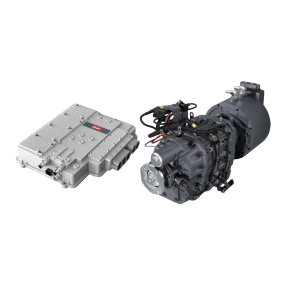
Danfoss ED-DT318B Installation And Operation Manual (186 pages)
Drive Train Systems with Traction Control Converter and Machine with 2 Speed Transmission
Brand:
Danfoss
| Category:
Industrial Equipment
| Size: 4 MB
Table of Contents
Table of Contents
2
List of Figures
5
Introduction
9
Table 1.1: ED-DT318B Systems
9
About this Guide
10
Conventions
10
Control Units
11
Safety Information
11
High Voltage Safety Information
11
Packaging and Disassembly
12
The Following Items Are Included in the Packaging
12
System Overview
12
Figure 1.1: Block Diagram of the Total System
13
Vehicle Control Unit
14
Installation
15
Avoiding Installation Problems
15
Installing the Mcu/Controller
15
General Notes
15
Vibration Considerations
16
Cable Routing
16
Preparing the Coolant Loop for MCU and Motor
16
Routing the Signal Cable
16
Routing the TCU to MCU Interface Cable
17
Applying Voltage
17
Installing the Motor & 2 Speed Transmission
17
Connection of the Driveline to the Transmission Output Flange
17
Mounting the Motor/Transmission into the Vehicle
18
Figure 2.1: Left Side - Attachment Points for Bell Housing & Transmission Mounting Brackets
18
Figure 2.2: Right Side - Attachment Points for Bell Housing & Transmission Mounting Brackets
19
Figure 2.3: Approved Location of Vibration Isolators
19
Overall Clearance Recommendation
20
Figure 2.4: Mounting Angle Limits
20
Motor Coolant Connections
21
Transmission Initial Set-Up and Requirements
21
Transmission Oil/Fluid
21
Figure 2.5: Direction of Rotation in Forward
21
Figure 2.6: Proper Lubricant Level
22
Figure 2.7: Transmission Lubricant Drain
23
Transmission Oil Cooler
24
Figure 2.8: Eaton Transmission Lubricant Ports
25
Figure 2.9: Lubricant Drain Port
25
Eaton Recommended Coolers
26
Figure 2.10: Eaton 18025 Oil to Air Cooler
26
Figure 2.11: Eaton 18025 Cooler Heat Transfer Based on 38° C (100° F) Temperature Differential
26
Figure 2.12: Eaton 5586750 Oil to Water Heat Exchanger
27
Figure 2.13: Eaton 5586750 Heat Exchanger Heat Transfer
27
Air Supply to the Transmission
28
Electro-Magnetic Interference and Compatibility
29
Figure 2.14: Pneumatic System
29
CAN and RS232 Shielding
30
Electrical Connections
31
Power Cables
31
Phase Cables (3 Phase AC Cables)
32
Figure 3.1: Controller Phase Connection
32
Figure 3.2: Controller Connections
32
DC Cables
33
High Voltage Interlock Connection
33
Figure 3.3: HVIL Daisy Chain Routing Thrugh the Controller and Motor
34
Termination Cover Installation
35
Phase Cable and DC Cable Routing and Air Flow Requirement
35
Figure 3.4 Exploded View of the Controller Connections
35
Grounding Requirements
36
Signal Cable
36
Figure 3.5: Signal Cable Connection - Insertion
37
Figure 3.6: Signal Cable Connection - Tightening
37
Figure 3.7: Signal Cable Connection - Final Torque
37
TCU to MCU Interface Cable
38
Drivetrain Interface Connector
38
Figure 3.8: Connector Bracket
38
Figure 3.9: Drivetrain Interface Connector (Connector 3)
40
Table 3.1: Drivetrain Interface Connector (Connector 3) Pinout
40
Figure 3.10: Danfoss Power Solutions Specification for 2 Lead Twisted Pair Shielded Wire
42
Figure 3.11: Drivetrain Interface Connector Terminals and Wire Seals
43
DT2 Diagnostic Connector
44
Figure 3.12: Allowed VCU to TCU CAN Bus Configurations
44
Table 3.2: RS232 Communications Pinout
45
Table 3.3: DT2 Diagnostic Connector (Connector 4) Pinout
45
Figure 3.13: TCU to MCU CAN Bus
46
Liquid Cooling MCU and Motor
47
Coolant Loop Requirements
47
Figure 4.1: Recommended Liquid Cooling Setup
47
Flow Rate Vs. Pressure Drop
48
Table 4.1: Liquid Cooling System Requirements
48
Electric Vehicle System Operation
49
Electric Vehicle System Overview
49
Figure 5.1: Block Diagram of Electric Vehicle Drive System
49
Valid Control Modes Via CAN
50
Special Features
50
Acceleration Control
50
Safety Features
51
Limits
51
Table 5.1: Potential Limitations
51
Forced Voltage Control
53
Stall
53
Forced Open Loop
53
Software Watchdog Timer
53
Vehicle Responses to Danfoss Power Solutions CAN Status Messages
54
Communications
55
VCU to TCU CAN Communications
55
TCU to MCU CAN Monitor
55
RS232 Communications
56
DT2 Diagnostic Connector
56
VCU to TCU CAN Bus
57
CAN Messages
57
Abbreviations
57
Boolean Values
58
Hexadecimal Values
58
VCU to TCU Command Messages
59
TCU Command Message 1
59
TCU Command Message 2
65
TCU to VCU Status Messages
69
TCU Status Message 1
69
TCU Status Message 2
74
TCU Status Message 3
95
TCU Status Message 4
110
TCU Status Message 5
113
TCU Status Message 6
116
TCU Status Message 7
119
Motor Diagnostic Software
123
Figure 8.1: Danfoss Power Solutions Motor Diagnostic Software Front Panel
123
Figure 8.2: Menu Bar
124
Figure 8.3: General Group
124
Figure 8.4: Data Logging Control
124
Figure 8.5: Status Group
124
Figure 8.6: Physical Group
124
Figure 8.7: Control Group
124
Figure 8.8: Electrical Group
124
Figure 8.9: Data Acquisition (DAQ) Control
124
Figure 8.10: Critical Group
124
Figure 8.11: Status Bar
124
Setting up the Software
125
Starting the Software
125
Figure 8.12: Choose COM Port Dialog Box
125
Table 8.1: Components of a Danfoss Power Solutions Motor Diagnostic Software Installation
125
Status Bar
126
Figure 8.13: Status Bar
126
Table 8.2: Status Bar Communication Messages
126
Diagnostic Software Operation
127
Table 8.3: Front Panel Group Descriptions
127
Measurement Update Speed
128
Status Group
129
Figure 8.14: Status Group
129
Table 8.4: Status Group Problems
129
Menu Bar and Toolbar
133
Figure 8.15: Menu Bar and Toolbar
133
Table 8.5: Menu and Toolbar Descriptions
133
Logging Data
134
Logging Set up
135
Figure 8.16: Front Panel Components of Logging
135
Table 8.6: Front Panel Logging Group Components
135
Figure 8.17: Logging Set up Dialog Box
136
Table 8.7: Logging Set up Components
136
Table 8.8: Logging and DAQ Measurement Columns
137
Data Acquisition
141
Table 8.9: DAQ Configuration Menu
141
Figure 8.18: Front Panel Components of DAQ
142
Table 8.10: Front Panel DAQ Group Components
142
Table 8.11: DAQ Trigger Descriptions
143
DAQ Set up
145
Figure 8.19: DAQ Setup
146
Figure 8.20: DAQ Trigger Thresholds
146
DAQ Set up Example
147
Table 8.12: DAQ Set up Components
147
Event Log
148
Figure 8.21: Event Dialog Box
149
Table 8.13: Possible Entries in Event Log
149
Figure 8.22 Mark Event Log with Today's Date Dialog Box
152
Appendix A: Vibration Testing
153
Controller Vibration Testing
153
SAE J1455 Vibration Test
153
Figure 9.1: Controller Axis Orientation
153
T 18488.1-2015 Vibration Test
154
Figure 9.2: SAE J1455 PSD Bobtail Vertical MID Frame, Heavy-Duty Truck Profile
154
Table 9.1: Severe Grade of Frequency Sweep Vibration Test
155
Appendix B: Vehicle Responses to Danfoss Power Solutions' CAN Status Messages
156
Vehicle Responses to Danfoss Power Solutions' CAN Status Messages
156
Table 10.1: System Status Signals
157
Table 10.2: Error Response Delay Time
176
Appendix C: Glossary
177
Abbreviations
178
Appendix D: Safety Notices
179
Advertisement
Advertisement
Related Products
Danfoss ET6200
Danfoss ET6110
Danfoss ET6100
Danfoss ET5040
Danfoss ET4020
Danfoss EKE
Danfoss EKE 100
Danfoss ED3
Danfoss ET4040-115
Danfoss APP 11 Ex / 1200
Danfoss Categories
Controller
DC Drives
Thermostat
Control Unit
Air Compressor
More Danfoss Manuals
Login
Sign In
OR
Sign in with Facebook
Sign in with Google
Upload manual
Upload from disk
Upload from URL