Table of Contents
Advertisement
BOCK
F/F-NH
®
Operating guide
F2, F3
F4, F5
F14/1166, F14/1366
F16/1751, F16/2051
FX2, FX3
FX4, FX5
FX14/1166, FX14/1366
FX16/1751, FX16/2051
Translation of the original instructions
3
F2 NH3, F3 NH
3
F4 NH3, F5 NH
3
F14/1166 NH
, F14/1366 NH
3
F16/1751 NH
, F16/2051 NH
3
3
3
AQ449946687878en-000201
Advertisement
Table of Contents

Related Manuals for Danfoss BOCK F


Summary of Contents for Danfoss BOCK F
- Page 1 BOCK F/F-NH ® Operating guide F2, F3 F2 NH3, F3 NH F4, F5 F4 NH3, F5 NH F14/1166, F14/1366 F14/1166 NH , F14/1366 NH F16/1751, F16/2051 F16/1751 NH , F16/2051 NH FX2, FX3 FX4, FX5 FX14/1166, FX14/1366 FX16/1751, FX16/2051 Translation of the original instructions AQ449946687878en-000201...
- Page 2 Observe the safety instructions contained in these instructions. These instructions must be passed onto the end customer along with the unit in which the compres- sor is installed. © Danfoss | Climate Solutions | 2023.07 2 | AQ449946687878en-000201...
-
Page 3: Table Of Contents
6.3 Spare parts recommendation / accessories 6.4 Lubricants / oil 6.5 Decommissioning Technical data F2-F16 Technical data F2 NH -F16 NH Dimensions and connections F 10 Dimensions and connections F-NH 11 Declaration of incorporation © Danfoss | Climate Solutions | 2023.07 AQ449946687878en-000201| 3... -
Page 4: Safety
As well as professions with comparable training, which enables personnel to assemble, install, maintain and repair refrigeration and air-conditioning systems. Personnel must be capable of assessing the work to be carried out and recognising any potential dangers. © Danfoss | Climate Solutions | 2023.07 4 | AQ449946687878en-000201... -
Page 5: General Safety Instructions
Only the refrigerant specified in these instructions may be used. Any other use of the compressor is prohibited! WARNING! The compressor may not be used in potentially explosive environments! © Danfoss | Climate Solutions | 2023.07 AQ449946687878en-000201| 5... -
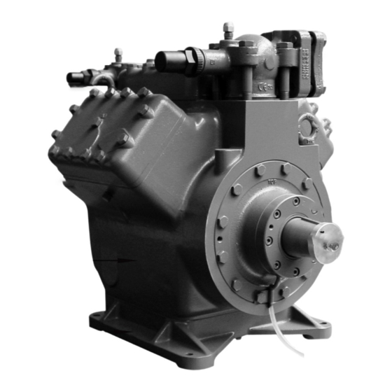
Page 6: Product Description
Discharge shut-off valve Cylinder cover Valve plate Suction shut-off valve Shaft seal Shaft end Oil sightglass Compressor housing Base plate Fig. 1 Dimension and connection values can be found in Chapter 9 © Danfoss | Climate Solutions | 2023.07 6 | AQ449946687878en-000201... -
Page 7: Name Plate
Transport eyelet Cylinder cover Transport eyelet Valve plate Shaft seal Shaft end Compressor housing Base plate Leak oil drain hose Fig. 3 Dimension and connection values can be found in Chapter 9 © Danfoss | Climate Solutions | 2023.07 AQ449946687878en-000201| 7... -
Page 8: Type Code
F 14 1166 NH version Swept volume ² Size Oil charge ¹ Series ¹ X - Ester oil charge (HFC refrigerant R134a, R404A/R507, R407C) ² Indication only at F14, F16 © Danfoss | Climate Solutions | 2023.07 8 | AQ449946687878en-000201... -
Page 9: Areas Of Application F, F
Fig. 5 3.3 Oil charge NH The compressors are filled with the following oil type at the factory: - for R717: Fuchs Reniso KC 68 © Danfoss | Climate Solutions | 2023.07 AQ449946687878en-000201| 9... -
Page 10: Operating Limits
700 - 1800 rpm F2 NH , F3 NH 960 - 1500 rpm F4 NH , F5 NH 500 - 1500 rpm F14 NH , F16 NH : 700 - 1500 rpm © Danfoss | Climate Solutions | 2023.07 10 | AQ449946687878en-000201... -
Page 11: Compressor Assembly
Correct setup of the compressor and mounting of the belt drive are decisive for running comfort, operating safety and the service life of Fig. 12 the compressor. © Danfoss | Climate Solutions | 2023.07 AQ449946687878en-000201| 11... -
Page 12: Maximum Permissible Inclination
Lay pipes correctly. Suitable vibration compensators must be provided to prevent pipes being cracked and broken by severe vibrations. Ensure a proper oil return. Keep pressure losses to an absolute minimum. © Danfoss | Climate Solutions | 2023.07 12 | AQ449946687878en-000201... -
Page 13: Laying Suction And Discharge Lines
Before opening or closing the shut-off valve, release the valve spindle seal by approx. ¼ of a turn counter-clockwise. After activating the shut-off valve, re-tighten the adjustable valve spindle seal clockwise. loosen tighten Valve spindle seal Fig. 16 Fig. 17 © Danfoss | Climate Solutions | 2023.07 AQ449946687878en-000201| 13... -
Page 14: Operating Mode Of The Lockable Service Connections
The connection which is not lockable is provided for safety devices. After activating the spindle, generally fit the spindle protection cap again and tighten with 14-16 Nm. This serves as a second sealing feature during operation. © Danfoss | Climate Solutions | 2023.07 14 | AQ449946687878en-000201... -
Page 15: Drive
Direct drive with shaft coupling: Direct drive with shaft couplings demands highly precise aligning of compressor shaft and motor shaft. Use the Bock shaft couplings „WK“ and observe the enclosed assembly instructions. © Danfoss | Climate Solutions | 2023.07 AQ449946687878en-000201| 15... -
Page 16: Oil Sump Heating Ru
Electrical power (Watt) INFO! Same electrical performance even on NH compressors WARNING! The oil sump heater must not be connected to the electrical circuit of the safety control chain ! © Danfoss | Climate Solutions | 2023.07 16 | AQ449946687878en-000201... -
Page 17: Commissioning
Evacuate the suction and discharge pressure sides using the vacuum pump. At the end of the evacuation process, the vacuum should be < 1.5 mbar when the pump is switched off. Repeat the process as often as is required. © Danfoss | Climate Solutions | 2023.07 AQ449946687878en-000201| 17... -
Page 18: Refrigerant Charge
Heavy shocks and vibrations to the shaft as well as continuous cyclic operation are to be avoided. The sealing surfaces can stick together during prolonged downtimes (e.g. winter). Therefore, run the system every 4 weeks for 10 minutes. © Danfoss | Climate Solutions | 2023.07 18 | AQ449946687878en-000201... -
Page 19: Shaft Seal Change
Particularly in critical systems (e.g. several evaporator points), measures are recommended such as replacement of liquid traps, solenoid valve in the liquid line, etc. There should be no movement of coolant whatsoever while the compressor is at a standstill. © Danfoss | Climate Solutions | 2023.07 AQ449946687878en-000201| 19... -
Page 20: Maintenance
6.3 Spare parts recommendation/accessories Available spare parts and accessories can be found on our compressor selection tool under vap.bock.de as well as at bockshop.bock.de. Only use genuine Bock spare parts! © Danfoss | Climate Solutions | 2023.07 20 | AQ449946687878en-000201... -
Page 21: Lubricants / Oil
When the compressor is depressurised, undo the fastening screws of the shut-off valves. Remove the compressor using an appropriate hoist. Dispose of the oil inside in accordance with the applicable national regulations. © Danfoss | Climate Solutions | 2023.07 AQ449946687878en-000201| 21... -
Page 22: Technical Data
7| Technical data F2 - F16 © Danfoss | Climate Solutions | 2023.07 22 | AQ449946687878en-000201... -
Page 23: Technical Data F2 Nh 3 -F16 Nh
8| Technical data F2-NH - F16-NH © Danfoss | Climate Solutions | 2023.07 AQ449946687878en-000201| 23... -
Page 24: Dimensions And Connections F
9| Dimensions and connections F Compressor type F2 H/D1 4xØ9 ca.255 Fig. 20 Dimensions in mm Shaft end F2 Woodruff key Cone Fig. 21 Dimensions in mm Dimensions for view X see page 31 © Danfoss | Climate Solutions | 2023.07 24 | AQ449946687878en-000201... - Page 25 9| Dimensions and connections F Compressor type F3 D/D1/H 4xØ9 96.5 ca.315 Fig. 22 Dimensions in mm Shaft end F3 Woodruff key Cone Fig. 23 Dimensions in mm Dimensions for view X see page 31 © Danfoss | Climate Solutions | 2023.07 AQ449946687878en-000201| 25...
- Page 26 Compressor type F4 ca.305 B DV ca.225 ca.455 Fig. 24 Dimensions in mm Shaft end F4 Woodruff key Cone Fig. 25 Dimensions in mm Dimensions for view X see page 31 © Danfoss | Climate Solutions | 2023.07 26 | AQ449946687878en-000201...
- Page 27 9| Dimensions and connections F Compressor type F5 ca.355 4xØ11 ca.470 Fig. 26 Dimensions in mm Shaft end F5 Woodruff key Cone Fig. 27 Dimensions in mm Dimensions for view X see page 31 © Danfoss | Climate Solutions | 2023.07 AQ449946687878en-000201| 27...
- Page 28 Dimensions in () = with elevated base plate Shaft end F14 Woodruff key Cone Leak oil Fig. 29 drain hose Dimensions in mm Dimensions for view X, Y see page 31 © Danfoss | Climate Solutions | 2023.07 28 | AQ449946687878en-000201...
- Page 29 Dimensions in () = with elevated base plate Shaft end F16 Woodruff key Cone Leak oil Fig. 31 drain hose Dimensions in mm Dimensions for view X, Y see page 31 © Danfoss | Climate Solutions | 2023.07 AQ449946687878en-000201| 29...
- Page 30 9| Dimensions and connections F © Danfoss | Climate Solutions | 2023.07 30 | AQ449946687878en-000201...
- Page 31 4 hole fastener on the side of the 1 item per compressor required. compressor *Please note that the legacy BOCK code numbers are without 097B Fig. 32 © Danfoss | Climate Solutions | 2023.07 AQ449946687878en-000201| 31...
-
Page 32: Dimensions And Connections F-Nh
H/D1 H/D1 4xØ9 4xØ9 ca.265 ca.265 Fig. 33 Dimensions in mm Shaft end F2 NH Woodruff key Cone Fig. 34 Dimensions in mm Dimensions for view X see page 39 © Danfoss | Climate Solutions | 2023.07 32 | AQ449946687878en-000201... - Page 33 Compressor type F3 NH D/D1/H 4xØ9 96.5 ca.345 Fig. 35 Dimensions in mm Shaft end F3 NH Woodruff key Cone Fig. 36 Dimensions in mm Dimensions for view X see page 39 © Danfoss | Climate Solutions | 2023.07 AQ449946687878en-000201| 33...
- Page 34 Passung 72636 Frickenhausen Germany www.bock.de ust. Änderungsbeschreibung Zone Änderungs-Nr. Datum Bearb. Gepr. Benzstraße 7 72636 Frickenhausen Germ Cone Fig. 38 Dimensions in mm Dimensions for view X see page 39 © Danfoss | Climate Solutions | 2023.07 34 | AQ449946687878en-000201...
- Page 35 Compressor type F5 NH 4xØ11 4xØ11 ca.470 ca.470 ca.355 ca.355 Fig. 39 Dimensions in mm Shaft end F5 NH Woodruff key Cone Fig. 40 Dimensions in mm Dimensions for view X see page 39 © Danfoss | Climate Solutions | 2023.07 AQ449946687878en-000201| 35...
- Page 36 Fig. 41 Dimensions in mm Shaft end F14 NH Woodruff key Cone Leak oil Fig. 42 drain hose Dimensions in mm Dimensions for view X, Y see page 39 © Danfoss | Climate Solutions | 2023.07 36 | AQ449946687878en-000201...
- Page 37 Datum Gepr. Bearb. Gepr. Benzstraße 7 72636 Frickenhausen Benzstraße 7 72636 Frickenhausen Germany www.b Cone Leak oil Fig. 44 drain hose Dimensions in mm Dimensions for view X see page 39 © Danfoss | Climate Solutions | 2023.07 AQ449946687878en-000201| 37...
- Page 38 10| Dimensions and connections F-NH © Danfoss | Climate Solutions | 2023.07 38 | AQ449946687878en-000201...
- Page 39 , F16 NH Second oil sight glass can be attached as an 4 hole oil sight glass option (available as original equipment only) 90° 4 x M6, 10 mm deep Fig. 45 © Danfoss | Climate Solutions | 2023.07 AQ449946687878en-000201| 39...
-
Page 40: Declaration Of Incorporation
Bock GmbH Authorized person for compiling and handing Alexander Layh over technical documentation: Benzstraße 7 72636 Frickenhausen, Germany Frickenhausen, 04th of January 2021 i. A. Alexander Layh, Global Head of R&D © Danfoss | Climate Solutions | 2023.07 40 | AQ449946687878en-000201... - Page 41 Bock GmbH Authorized person for compiling and handing Alexander Layh over technical documentation: Benzstraße 7 72636 Frickenhausen, Germany Frickenhausen, 14th of October 2022 i. A. Alexander Layh, Global Head of R&D © Danfoss | Climate Solutions | 2023.07 AQ449946687878en-000201| 41...
- Page 42 © Danfoss | Climate Solutions | 2023.07 42 | AQ449946687878en-000201...
Need help?
Do you have a question about the BOCK F and is the answer not in the manual?
Questions and answers