Table of Contents
Advertisement
Quick Links
Advertisement
Table of Contents

Related Manuals for Danfoss ET6110


Summary of Contents for Danfoss ET6110
- Page 2 Imprint Manufacturer: UNIFLEX-Hydraulik GmbH Robert-Bosch-Strasse 50-52 D-61184 Karben Germany Phone: +49 (0) 60 39 / 91 71 - 0 Fax: +49 (0) 60 39 / 91 71 - 181 This Operating Manual of the machine is a translation; the origi- nal is in German.
- Page 4 In accordance with EC Machinery Directive 2006/42/EC and UK-Sup- ply of Machinery (Safety) Regulations 2008. The following machine Danfoss ET6110 was developed, designed and manufactured in compliance with EC Directive 2006/42/EC and UK-Supply of Machinery (Safety) Regulations 2008, in the sole responsibility of...
-
Page 5: Table Of Contents
Contents About this document ..................7 1.1 Target groups ....................7 1.2 Storage ......................8 1.3 Name plate ....................9 Safety instructions .................... 10 2.1 Presentation of warnings ................10 2.2 Intended use ....................10 2.3 Product-specific risks .................. 11 2.3.1 Risks imposed by mechanical equipment ........ - Page 6 5.1 What you have to observe ................29 5.2 Start ......................29 5.3 Skiving the workpiece .................. 30 5.3.1 Prerequisites ..................30 5.3.2 Skiving the workpiece ............... 30 5.4 Stop ......................32 5.5 Emergency-stop ..................33 5.6 Cleaning ...................... 33 Maintenance .......................
-
Page 7: About This Document
About this document In this Operation Manual, the “hose skiving machine Danfoss ET6110“ is consistently referred to as machine. This Operation Manual includes important notes on how you operate your machine/unit safely, properly and economically. Use not in compliance with the intended purpose may result in hazard to the operator's health and life and/or in the risk of damage to/the machine/unit. -
Page 8: Storage
• persons working on the machine/unit are adequately qualified; • persons working on the machine/unit are suitable for operating the machine/unit; • the Operation Manual has been read and understood. One hard- copy of the Operation Manual must always be kept at a desig- nated place where the machine/unit is used. -
Page 9: Name Plate
Name plate The name plate is fixed near the power cable. -
Page 10: Safety Instructions
Safety instructions Presentation of warnings Warning notes in the Operation Manual warn against risks involved with the handling of the machine/unit. Risk levels are identified as fol- lows: The signal word HAZARD identifies an imminent hazard resulting in HAZARD! serious injuries or death. This warning is supplemented by a triangu- lar hazard symbol. -
Page 11: Product-Specific Risks
➢ persons with a restricted capability for the operation of ma- chines (e.g. under the influence of drugs, alcohol or narcot- ics) Use of the control in compliance with the intended purpose also in- cludes compliance with the instructions in this Operation Manual. Use for other than the intended purpose Any other use is considered as being not in compliance with the in- tended purpose, in particular:... -
Page 12: Risks Imposed By Mechanical Equipment
2.3.1 Risks imposed by mechanical equipment Cutting risk The skiving process and the skiving knife change-over imply a cutting risk. • Keep sufficient distance to the skiving knives during operation. • Take care when changing the skiving knives and wear protective gloves. -
Page 13: Risks Imposed By Substances
• instruct staff to wear ear protection, • provide information/instructions on risks, • identify hazardous areas, • provide health monitoring. 2.3.4 Risks imposed by substances Oils, greases and emulsions may penetrate the skin. When handling hazardous substances, oils and greases, the manufacturers' safety instructions have to be observed. -
Page 14: Safety
Safety 2.4.1 Working area The working area is designed as the area 1 metre all around the ma- chine (shaded). • Keep the working area free from trip hazards • Use ducts for lines and cables • Provide good illumination... -
Page 15: Emergency-Stop
2.4.2 Emergency-stop The machine is fitted with an emergency-stop switch on the control panel. Immediately activate the emergency-stop switch (1) on the control panel in cases of emergency. Remedy the cause of the emergency stop first before unlocking the emergency-stop switch. -
Page 16: Protection Equipment
2.4.3 Protection equipment The protection hood (1) covers the skiving area of the unit and is fit- ted with a safety switch. The safety switch is closed by the contact plug when the protection hood is closed. The safety switch switches off the motor when the hood is opened. - Page 17 Crushing risk on the cover Cutting risk on the skiving knives Danger from electric current at the power supply line Illegible or missing warning signs must immediately be replaced by the owner.
-
Page 18: Machine Description
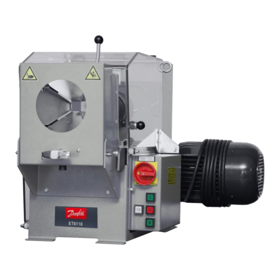
Machine description Design and function Basic machine (1) Protection hood (2) Safety switch (3) Electric motor (4) Main power switch (5) Control system (6) Opening lever (7) Protective flaps (8) Hose guide housing With USM 100, hose lines with wire braiding up to DN 50 and hose lines with wire spiral up to DN 50 - 6 SP can be peeled inside and outside simultaneously. -
Page 19: Operation And Display Elements
The hose is guided by hand through the protective flaps (7) centrally against the peeling blades. The hands remain outside the machine during this process. The motor operated skiving blades (3) rotate against each other and skive the hose line inside and outside simulta- neously from the hose end. -
Page 20: Technical Data
Technical data Machine Dimensions L x W x H 440 x 440 x 545 mm Weight approx. 35 kg Type of use Workshop Operation mode S3-60 % Noise level < 70 dB(A)* Protection class IP 40 Function Tool speed 110 rpm Workpiece capacity 5/8ʺ... - Page 21 Electric connection Connection power 0.37 kW Connected voltage 400 V 50 Hz, 3 phase+PE Back-up fuse 16 A delayed Gear oil Oil volume approx. 100 ml Oil type Shell Omala Oil 220 Workbench Solid, plane workbench with a carrying capacity of approx.
-
Page 22: Transport And Commissioning
Transport and commissioning Transport The goods should be transported in the original packaging. During transport, the goods must be secured safely within the packaging. All applicable laws and regulations relating to securing loads shall be ob- served during transport. The machine must only be unloaded and transported with a crane. When a crane is used for transport, lifting gear with a sufficient length and lifting capacity has to be used. - Page 23 • Weather influences, • Mechanical damage. The machine/unit components may only be stored in closed rooms and under the following conditions: • temperature between 10°C and 35°C, • maximum air humidity 80% (non-condensating).
-
Page 24: Commissioning
Commissioning The machine is commissioned by the customer's fitter. Place the machine on a stable and level workbench. Bolt the machine legs onto the workbench. The workbench must be sufficiently solid and stable. Place the machine in a way so that it is easily accessible for maintenance work from all sides. -
Page 25: Inserting The Internal Skiving Mandrel
4.3.1 Inserting the internal skiving mandrel Select the correct internal skiving mandrel (if several available) for the hose diameter. Push the stop sleeve (2) back on the internal knife holder (3) and hold. Insert the internal skiving mandrel as far as possible into the in- ternal mandrel holder (3). -
Page 26: Setting The Internal Skiving Diameter
4.3.2 Setting the internal skiving diameter Hold the skiving spindle. Remove the screw (7) in the tip of the skiving spindle. Assemble the centering sleeve (6) that is specified for this diam- eter. Assemble the right corresponding centering sleeve (6), depending on the nominal diameter of the hose assembly. -
Page 27: Adjusting The External Skiving Diameter
Insert the external skiving knife as far as possible into the exter- nal knife holder (1). Release the stop lever (4). Turn the external skiving knife until it audibly engages. Examine its tight fit. The external knife has to fit tight in the holder. 4.3.4 Adjusting the external skiving diameter Open the protection hood. -
Page 28: Electrical Connection
4.3.6 Electrical connection WARNING! Risk by electrical voltage! There is a risk of electrocution near the live parts! • Work on electric systems may only be performed by qualified electricians or instructed and trained persons under the su- pervision of a qualified electrician. •... -
Page 29: Operation
Operation What you have to observe The operator has received the Operation Manual from the owner, has read and understood it and will observe it. Before starting and/or re-starting • Ensure sufficient illumination of the working area of the ma- chine/unit. -
Page 30: Skiving The Workpiece
Skiving the workpiece 5.3.1 Prerequisites Prerequisites for a correct skiving process: • A suitable outside/inside skiving tool is selected. • The outside/inside skiving tool is inserted in the drive shaft. • The outside/inside skiving tool is secured by the locking pin / star-shaped grip. - Page 31 10. Pull the skived workpiece out of the skiving machine.
-
Page 32: Stop
Stop Complete the skiving process. Deposit the workpiece outside the machine. Deactivate the main power switch (1) and secure it against unin- tentional restart. Open the protection cover. Empty the chip box. Check the machine for contamination and outside damage. Check the skiving knife for damage and wear. -
Page 33: Emergency-Stop
Emergency-stop In case of an emergency Immediately deactivate the emergency-stop switch in cases of emer- gency. The motor is switched off immediately. The skiving tool move- ment is stopped. Restart after and emergency WARNING! Risk of injuries! The emergency-stop button was probably activated due to the occurrence of a hazardous situation. -
Page 34: Maintenance
Maintenance Regular maintenance will ensure the continuous operation reliability of the device. What you have to observe This Section describes action to be taken by you as the fitter regularly to ensure the troublefree use of the machine/unit. • Maintenance work may only be performed by qualified mainte- nance staff (machine/unit fitters). - Page 35 Maintenance item Skiving knife Check skiving knife - for sharpness, cracks and breakouts; resharpen or replace knives as appropri- ate. Bolted connections: To be checked and retightened, if required. Machine - Clean Safety equipment Emergency-stop switch. Check function. Safety switch: Check function. Check permanently installed partitioning protection equipment and covers for completeness and correct installation.
-
Page 36: Replacing The Skiving Knives
Replacing the skiving knives WARNUNG! Risk of cutting! There is an acute risk of injury to the hands when changing the knife. • Wear safety gloves when working on the knives. WARNUNG! Risk by electrical voltage! There is a risk of electrocution near the live parts! •... -
Page 37: Replacing The External Skiving Knife
Hold the hose guide (4) and turn the opening lever (3). This un- locks the retaining bolts of the hose guide (4). Carefully tilt the hose guide (4) downwards. Release the locking lever (2) of the skiving tool. Pull the skiving tool forward out of the shaft. 6.3.2 Replacing the external skiving knife ATTENTION! Risk of damage to machinery! -
Page 38: Replacing The Internal Skiving Knife
6.3.3 Replacing the internal skiving knife ATTENTION! Risk of damage to machinery! Worn skiving knives may cause damage to the machine and skiv- ing inaccuracies. • Check the skiving knives daily. Loosen the screws (1) (Figure A). Take out the skiving knife by loosening the setting screw (2) (Fig- ure B). -
Page 39: Changing Break Pads
Check the adjusted diameter. Changing break pads Exchange any abraded break pads, if the break pad is thinner than 2 mm. Loosen the rear cover plate. Loosen the two screws of each break pad. Insert new break pads and re-fasten with the two screws. -
Page 40: Troubleshooting
Troubleshooting Error Cause Remedy Machine does not skive Power switch is OFF Activate the power switch Voltage incorrect Check voltage supply Power plug defective Check power plug and replace, if required Incorrect rotation direction of Check rotation direction, cor- electric motor rect electrical connection Foot pedal not connected to Check cable connection be-... -
Page 41: Decommissioning, Disposal
Decommissioning, disposal WARNING! Risk by electrical voltage! There is a risk of electrocution near the live parts! • Shut down the machine/unit. • Disconnect the machine/unit from the power supply. CAUTION! Risk of injuries! Contact with hydraulic oil and other consumables imposes a risk of injuries for the skin, eyes, respiratory and intestinal tracts! Hy- draulic liquid spills impose danger of slipping and falling! •... -
Page 42: Dismantling
CAUTION! Risk of injuries! Parts of the machine/unit may be under pressure and/or tension. Loosening components may impose a risk of injuries! • De-pressurize the machine/unit before performing any work and check for potential sources of hazard. Dismantling This section describes activities to be performed by you as the opera- tor to ensure the safe dismantling of the machine/unit. - Page 43 Return consumables, e.g. oils, greases, test media, to supplier - they are hazardous waste. Also observe the information given on the safety data sheet.
-
Page 44: Annex
Annex Individual machine/unit components may deviate in their features. Please indicate the serial number of the machine for spare part or- ders. Accessories (retrofittable) Accessories Article code Workbench Hose slitting machine Drill DN 6 ID ¼ UIT 6 Drill DN 8 ID 5/6 UIT 8 Drill DN 10 ID 3/8 UIT 10... - Page 45 Accessories Article code Adjustment mandrel DN 32 UOP 32 Adjustment mandrel DN 40 UOP 40 Adjustment mandrel DN 50 UOP 50 Adjustment mandrel DN 60 UOP 60 Please contact our Sales Department for ordering optional accesso- ries.
-
Page 46: Spare Parts List
Spare parts list Item Quantity Part code Designation 307.026 Hinge 307.225.1 Macrolon safety glass 307.027 Electric motor... - Page 47 Item Quantity Part code Designation T0-2-1/ea/SvB Main switch QXT + BSOX 43 + Button motor on I T25F GN QXT + BSOX 42 + Button motor off T25F RT QXT + BSOX 44 + Button motor on II T25F RT M 12 DIN 982 + DIN Nut + Washer 9021 Ø13...
- Page 48 Position Anzahl Artikelnummer Bezeichnung 307.257.3 Pulley...
- Page 49 Position Anzahl Artikelnummer Bezeichnung 307.032.4 Tensioner 307.012.4 Pulley DIN 975 M 10x245 Threaded rod 307.006.3 Socket 307.012 Coupling socket 307.005 Locking bolt 307.040 Round spring UIT xx Internal skiving mandrel UOP xx Internal holding mandrel 307.053.4 External skiving blade UOT 06 – 50 External skiving tool 307.007.4 Belt pulley...
-
Page 50: Spare Parts Set
Spare parts set Quantity Part code Designation 307.053 Spare part set... -
Page 51: Electric Diagram
Electric diagram... -
Page 52: Maintenance Log
Maintenance log Remark Date Signature ... -
Page 53: Declaration Of Qualified Staff
Declaration of qualified staff I herewith declare that I have attended an internal training for the op- eration of the UNIFLEX machine and have been informed on all safety-related details. In addition I declare that I have read and under- stood this Operation Manual completely.
Need help?
Do you have a question about the ET6110 and is the answer not in the manual?
Questions and answers