Table of Contents
Advertisement
Quick Links
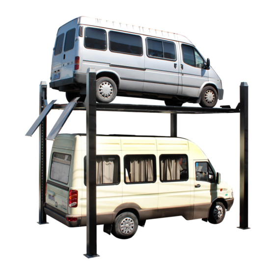
4 POST HOIST
AutoLift 163027
Extra High 4 Post Storage Vehicle Hoist
3200Kg Maximum Lifting Capacity
Design Registration Approval Number: N/A - Domestic Application
Design Code: AS1418.9-19966
Note: While all due care and attention has been taken in the preparation of this document, Advance AutoQuip shall not be liable for any inaccuracies or omissions
INSTALLATION MANUAL & OPERATION
INSTRUCTIONS
- READ THE ENTIRE CONTENTS OF THIS MANUAL BEFORE
INSTALLATION AND OPERATION. BY PROCEEDING YOU AGREE THAT
YOU FULLY UNDERSTAND AND COMPREHEND THE FULL CONTENTS
OF THIS MANUAL. FORWARD THIS MANUAL TO ALL OPERATORS.
FAILURE TO OPERATE THIS EQUIPMENT AS DIRECTED MAY CAUSE
Specifications subject to change without notice.
2 McDonald Crescent | Bassendean WA 6054
Ph: 08 9279 1663 | Fax: 08 9279 1667 | E: sales@aaq.net.au | W: www.aaq.net.au
INJURY OR DEATH.
which may occur therein
Advance AutoQuip
READ FIRST
DO NOT use the
machine until you read
and understand all the
dangers, warnings and
cautions in this manual.
Advertisement
Table of Contents

Related Manuals for AAQ AutoLift 163027


Summary of Contents for AAQ AutoLift 163027
- Page 1 Note: While all due care and attention has been taken in the preparation of this document, Advance AutoQuip shall not be liable for any inaccuracies or omissions which may occur therein Advance AutoQuip 2 McDonald Crescent | Bassendean WA 6054 Ph: 08 9279 1663 | Fax: 08 9279 1667 | E: sales@aaq.net.au | W: www.aaq.net.au...
-
Page 2: Table Of Contents
TABLE OF CONTENTS Important Note--------------------------------------------------------------------------------Page 3 Definition and Preparation ---------------------------------------------------------------Page 4 General Information ------------------------------------------------------------------------Page 5 Important Concrete and Anchoring Information--------------------------------------Page 6 Installation and Basic Operation Instruction------------------------------------------Page 7 Safety Procedures---------------------------------------------------------------------------Page 14 Maintenance Schedule---------------------------------------------------------------------Page 15 Troubleshooting------------------------------------------------------------------------------Page 17 Owners Responsibilities-------------------------------------------------------------------Page 18 Packing list -----------------------------------------------------------------------------------Page 19 Installation specification ------------------------------------------------------------------Page 20 Parts drawing -------------------------------------------------------------------------------Page 21 Parts code list ------------------------------------------------------------------------------Page 26... -
Page 3: Important Note
IMPORTANT NOTES ● Do not install this hoist on any surface other than concrete confirming to minimum specifications. ● Do not install this hoist over expansion joints or cracks. Check with building architect. Do not install this hoist on a second floor with a basement beneath without written authorization ●... -
Page 4: Definition And Preparation
DEFINITION The hoist is a Four-Column Flat Deck Hydraulic, cable driven one. The name / model numbers is designated below: Surface Mounted 4-Post Flat Deck Storage Hoist with 3200KG Lifting Capacity. Model number: 163027 This hoist is a 3200kg capacity, 4-post hoist. The safety latch system is very similar to an extension ladder. -
Page 5: General Information
GENERAL INFORMATION 1. Carefully remove the crating and packing materials. CAUTION! Be careful when cutting steel banding material as items may become loose and fall causing personal harm or injury. 2. Identify the components and check for damage or shortages. If damage or shortages are discovered, contact distributor immediately. -
Page 6: Important Concrete And Anchoring Information
IMPORTANT CONCRETE AND ANCHORING INFORMATION 1. Concrete shall have compression strength of at least 3,000 PSI and a minimum thickness of 125mm in order to achieve a minimum anchor embedment of 85mm. When using the standard supplied long anchors, if the top of the anchor exceeds 55mm above the floor grade, you DO NOT have enough embedment. -
Page 7: Installation And Basic Operation Instruction
INSTALLATION INSTRUCTION IMPORTANT NOTICE These instructions must be followed to insure proper installation and operation of your hoist. Failure to comply with these instructions can result in serious bodily harm and void product warranty. Manufacturer will assume no liability for loss or damage of any kind, expressed or implied resulting from improper installation or use of this product. - Page 8 STEP 2: (Unloading and Unpacking) After unloading the hoist, place it near the intended installation location. (Fig. 3) Check the items with packing list. Remove the shipping bands and packing materials from the unit. Remove the packing brackets and bolts holding the two runways together.
- Page 9 Fig. 4 power-side column Fig. 5 Fig. 6 Bolt the safety rack on both end. (Fig. 7 & 8 ) Raise up the cross bar ends to rest on the first (lowest) position. (Fig. 9) Fig.7 Fig. 8 Fig. 9 Again check all the position of the columns according to the drawings.
- Page 10 latch is off the rack. Be sure the cables are in its pulley under the runway . Fig.14 Fig.15 5. Tighten all the bolts on the power-side runway with supplied bolts, nuts, and spring washes. SUGGESTION Pull out the ram of the cylinder underneath the power-side runway as longer as possible, to make the cables reach the column top easily.
- Page 11 Using the level, by screwing up or down of the nut of the cable on the column top one by one , make the cross bar level and also the runway are level too. (Fig. 21, 22) Fig. 21 Fig. 22 Using the level, by screwing up or down of the nut of the safety rack on the column top one by one , make the cross bar level and also the runway are level too while hoist is in lock.
- Page 12 STEP 10: (Hoist anchored) Using the base plate on the column as a guide, drill each anchor hole in the concrete approximately 140mm deep using a rotary hammer drill and ” concrete drill-bit. To assure full holding power, do not ream the hole or allow the drill to wobble. After drilling, remove dust thoroughly from each hole using compressed air and/or wire brush.
- Page 13 VEHICLE PARKING 1. Lower the runways to the ground. Put on the front stops and ramps. 2. Drive the vehicle on the ramps. Take off the ramps and lock the vehicle by insert stops under the wheels. Check again the vehicle on the hoist is safe. 3.
-
Page 14: Safety Procedures
SAFETY PROCEDURES Never allow unauthorized persons to operate hoist. Thoroughly train new employees in the operation and care of hoist. Caution: the power unit operates at high pressure. Remove passengers before raising vehicle. Prohibit unauthorized persons from being in shop area while hoist is in use. Total lift capacity is 3200kg. -
Page 15: Maintenance Schedule
MAINTENANCE SCHEDULE The following periodic maintenance is the suggested minimum requirements and minimum intervals; accumulated hours or monthly period, which ever comes sooner. If you hear a noise or see any indication of impending failure - cease operation immediately – inspect, correct and / or replace parts as required. - Page 16 YEARLY MAINTENANCE Lubricate cable Grease rub blocks and column surface contacting rub blocks Change the hydraulic fluid- good maintenance procedure makes it mandatory to keep hydraulic fluid clean. No hard fast rules can be established;-operating temperature, type of service, contamination levels, filtration, and chemical composition of fluid should be considered.
-
Page 17: Troubleshooting
TROUBLE SHOOTING 1. Motor dose not run: A. Breaker or fuse blown B. Motor thermal overload tripped. Wait for overload to cool. C. Faulty wiring connections call electrician. D. Defective up button call electrician for checking. 2. Motor runs but will not raise: A. -
Page 18: Owners Responsibilities
OWNER / EMPLOYER RESPONSIBILITIES The owner/Employer: Shall establish procedures to periodically maintain, inspect and care for the hoist in accordance with the manufactures recommended procedures to ensure its’ continued safe operations. Shall provide necessary lockout / tag outs of energy sources before beginning any hoist repairs. -
Page 19: Packing List
Packing list Description Note Power-side runway with cylinder ,hose and cables Off-side runway Front cross bar Rear cross bar Power-side column With mounting holes for pump Off-side column wheel stop Approach ramp Beam cover Accessory box Anchors and shims Electro-hydraulic pump ITEM MODEL 163027 5360mm... -
Page 20: Installation Specification
INSTALLATION SPECIFICATION OF PARKING HOIST 163027 1185-1612mm 485mm 3220mm 3820mm Fig. 40... -
Page 21: Parts Drawing
PARTS & DRAWING OF 163027 PARKING HOIST 30/31 7.1/7.2 10/11 32/33 13/14/15/16 19/20 24/25/26/27 Fig.41... - Page 22 PARTS & DRAWING OF 163027 PARKING HOIST ( safety lock system) 75/76 38/39 40/41 45/46 48/49 63 62 52/53 50/51 Fig. 42...
- Page 23 PARTS & DRAWING OF 163027 PARKING HOIST (cylinder and motor pump connection) Fig. 43...
- Page 24 PARTS & DRAWING OF 163027 PARKING HOIST ( cable wiring) 1 0 1 1 0 0 1 0 2 1 0 6 1 0 3 Fig 44...
- Page 25 PARTS & DRAWING OF 163027 PARKING HOIST 110/111/112 91/92 98/99 Fig 45...
-
Page 26: Parts Code List
PARTS CODE OF 163018 FOUR-POST PARKING HOIST ITEM CODE DESCRIPTION NOTE 163027*01-001 column 3# 163027*01-002 main platform 163027*01-003 column 1# 163027*01-004 motor pump 163027*01-005 column 2# 163027*01-006 sub platform 163027*01-007 ramp 163027*01-007.1 ramp wheel 163027*01-007.2 Circlip 163027*01-008 shaft 163027*01-009 Circlip 163027*01-010 flat washer 163027*01-011... - Page 27 ITEM CODE DESCRIPTION NOTE 163027*03-038 shaft 2# 163027*03-039 Circlip 163027*03-040 shaft 3# 163027*03-041 Circlip 163027*03-042 nylon block 163027*03-043 screw M6X12 163027*03-044 screw M6X35 163027*03-045 shaft 4# 163027*03-046 Circlip 163027*03-047 M6X10 screw 163027*03-048 cross bar 1# 163027*03-049 cross bar 2# 163027*03-050 bearing slot 1# 163027*03-051 bearing slot 2#...
- Page 28 ITEM CODE DESCRIPTION NOTE 163027*03-075 screw M6X10 163027*03-076 washer 163027*03-077 cross bar cover 163027*03-078 cable broken block 2# 163027*03-079 cable broken wheel 163027*05-080 hose 2# 163027*05-081 valve switch 163027*05-082 fixing board 163027*06-083 cable 1# L=6240 163027*06-084 cable 2# L=8270 163027*06-085 cable 3# L=13310 163027*06-086...
- Page 29 SAFETY OPERATING PROCEDURES Vehicle Hoist DO NOT use this machine unless the operator has been thoroughly instructed in its safe use and operation. Safety glasses must be worn at all Long and loose hair must be times in work areas. contained.
- Page 30 THIS WARRANTY SUPERSEDES ALL OTHER WARRANTY POLICIES PREVIOUSLY STATED AND IN ALL OTHER ADVANCE AUTOQUIP’s PRODUCT SPECIFIC LITERATURE. Advance AutoQuip 2 McDonald Crescent | Bassendean WA 6054 Ph: 08 9279 1663 | Fax: 08 9279 1667 | E: sales@aaq.net.au | W: www.aaq.net.au...
- Page 31 COMMISSIONING REPORT 1. Details of Customer Customer Name: Installation Address: 2. Hoist Details Model No: 2 McDonald Crescent Hoist Type: Bassendean WA 6054 Installation Date: P: 08 9279 1663 | E: sales@aaq.net.au 3. Commissioning Report Comments Safety Devices Safety devices incorporated into the design of the vehicle to AS/NZS 1418.9 Welds Visual check all welds completed and comply to requirement of AS/NZS 1554 Hydraulic Equipment and Controls Visual check carried out for leaks Pneumatic Equipment and Controls Visual check carried out for leaks Safety Locks Safety locks tested for correct operation Support Pads Checked for good working order Wheel Stops Supplied with the hoist and in good working order Hoist Motion Limits Checked for correct operation Load Test and Speed Check Hoist checked with load for correct operation and speed control tested Wire Ropes Checked wire ropes for correct installation and tension Concrete Floor Concrete floor is a suitable depth for installation...
- Page 32 COMMISSIONING REPORT Location of Vehicle Hoist & Vehicle Clearances Vehicle hoist or any part of the load is positioned no less than 600mm away from any fixed structure Provisions have been made for effective clearances above the vehicle when the hoist is in its fully raised position. Markings ‐ Hoist Checked for Relevant Marking Including: Make & Model Number Serial number Rated Capacity Reference to maintenance Operation instructions Screw and Nut Gaps Hoist compliance plate showing design registration Functional Test Vehicle hoist has been tested and all safety devices, limit switches and control function interlocks have been tested for correct operation. Demonstration The installer has demonstrated the operation of the vehicle hoist to the owner or operator Electrical Equipment and Controls Lock off isolating switch installed Emergency stop button installed 3. Details of Electrical Contractor Trading Name: EC Licence Number: Address: Telephone Number: 4. Signature Name: ___________________________________________________________ Date: I, being the person responsible for completing the commissioning report have exercised reasonable skill and competency when completing the report and herby certify that the vehicle hoist has been commissioned fit for use as per the Australian / New Zealand Standard 1418.9:1996 Vehicle Hoists.
Need help?
Do you have a question about the AutoLift 163027 and is the answer not in the manual?
Questions and answers