Table of Contents
Advertisement
Quick Links
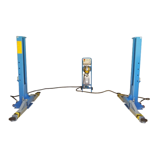
2 POST HOIST
AutoLift 167212E
2 Post Movable Vehicle Hoist
2700Kg Lifting Capacity
Design Registration Approval Number: N/A Domestic Application Only
Design Code: AS1418.9-1996
Note: While all due care and attention has been taken in the preparation of this document, Advance AutoQuip shall not be liable for any inaccuracies or omissions
Ph: 08 9279 1663 | Fax: 08 9279 1667 | E: sales@aaq.net.au | W: www.aaq.net.au
INSTALLATION MANUAL & OPERATION
INSTRUCTIONS
- READ THE ENTIRE CONTENTS OF THIS MANUAL BEFORE
INSTALLATION AND OPERATION. BY PROCEEDING YOU AGREE THAT
YOU FULLY UNDERSTAND AND COMPREHEND THE FULL CONTENTS
OF THIS MANUAL. FORWARD THIS MANUAL TO ALL OPERATORS.
FAILURE TO OPERATE THIS EQUIPMENT AS DIRECTED MAY CAUSE
Specifications subject to change without notice.
which may occur therein
Advance AutoQuip
2 McDonald Crescent | Bassendean WA 6054
INJURY OR DEATH.
READ FIRST
DO NOT use the
machine until you read
and understand all the
dangers, warnings and
cautions in this manual.
Advertisement
Table of Contents

Subscribe to Our Youtube Channel
Related Manuals for AAQ 167212E


Summary of Contents for AAQ 167212E
- Page 1 Note: While all due care and attention has been taken in the preparation of this document, Advance AutoQuip shall not be liable for any inaccuracies or omissions which may occur therein Advance AutoQuip 2 McDonald Crescent | Bassendean WA 6054 Ph: 08 9279 1663 | Fax: 08 9279 1667 | E: sales@aaq.net.au | W: www.aaq.net.au...
- Page 2 Capacity, Symmetric Swing Arm set up with simple type control box. Model number: 167212E. The hoist is designed for the DIY’ers, enthusiasts, and shop owners. It has the ability of a full size two post hoist, but also has the convenience of a portable hoist. The work is done by a 2” cylinder directly, driven by a electric-hydraulic power unit capable of providing 3,000psi hydraulic pressure.
-
Page 3: General Information
*Every column with its cylinder, carriage, lifting arms, pad with holders, oil pipes, and cart. Accessory box is in one column. *There is the hydraulic motor pump in one carton separately. The power supply for the motor pump of this hoist is 240V/50Hz, single phase, 15A. 167212E Nov. 2016 3... -
Page 4: Anchoring Tip Sheet
7. Do not use an impact wrench to tighten. Tighten the nut two or three turns on average concrete (28-day cure). If the concrete is very hard, only one or two turns may be applied. Check each anchor bolt with torque wrench set to 80 foot pounds. 167212E Nov. 2016 4... -
Page 5: Installation Instruction
DEFECTIVE CONCRETE: Visually inspect the site where the hoist is to be installed and check for cracked or defective concrete. FLOOR REQUIREMNETS: The hoist should be installed on a 3000 PSI concrete with little gradients. Fig. 2 167212E Nov. 2016 5... - Page 6 Fig. 3 167212E Nov. 2016 6...
- Page 7 Move the columns to the position over the recessed anchors (See Fig. 6). Make sure the bolt holes line up with the recessed anchors in the concrete. Secure each column to the floor using the five 5/8”*2” high-yield bolts. Fig. 5 Fig. 6 167212E Nov. 2016 7...
- Page 8 Open the control box. Connect the motor cable and the release valve cable to the terminals according to the drawing on the back of the box cover.. Fig. 10 cart Fig. 11 valve Fig. 12 pump 167212E Nov. 2016 8...
- Page 9 : Warning the wiring must comply with local code. Have a certified electrician make the electrical hook-up to the power unit. Protect each circuit with time delay fuse or circuit breaker 108V-130V single Phrase 30 Amp. 167212E Nov. 2016 9...
- Page 10 7. Raise vehicle to desired working height. Put the locking bar into the holes on the column. Then, to lock the hoist you must press the lower level to relieve the hydraulic pressure and let the carriage set on the locking bars. 167212E Nov. 2016 10...
- Page 11 5. Before removing vehicle from hoist area, position the hoist arms and supports to provide an unobstructed exit. WARNING: Never drive over hoist arms. Note: It is normal for an empty hoist to lower slowly and asynchronous. 167212E Nov. 2016 11...
- Page 12 10. Press the switch to raise or the lever at the power unit to lower the hoist. WARNING: During single column working, just one hose and only the T-fitting is connected. Fig. 21 Fig. 22 to column 167212E Nov. 2016 12...
-
Page 13: Maintenance Schedule
Good maintenance procedure makes it mandatory to keep hydraulic fluid clean. No hard fast rules can be established. Operating temperature, type of service, contamination levels, filtration, and chemical composition of fluid should be considered. If operated in dusty environment, shorter interval may be required. 167212E Nov. 2016 13... - Page 14 Air hoses can be used to clean fittings and other components. However, the air supply must be filtered and dry to prevent contamination. Contamination is the most frequent cause of malfunction or hydraulic equipment. 167212E Nov. 2016 14...
-
Page 15: Troubleshooting
B. Rod end of cylinder------The rod seal of the cylinder is out. Rebuild or replace the cylinder. C. Breather end of the cylinder------the piston seal of the cylinder is out. Rebuild or replace the cylinder. Hoist makes excessive noise. Rub block on carriage of the hoist is dry and requires grease. 167212E Nov. 2016 15... -
Page 16: Owner / Employer Responsibilities
Shall insure that hoist operators are instructed in the proper and safe use and operation of the hoist using the manufacturer’s instructions and “Lift It Right: and “safety Tips” supplied with the hoist. 167212E Nov. 2016 16... - Page 17 PARTS CODE AND DRAWING Fig. 24 (column, carriage, lifting arm & cylinder ) 167212E Nov. 2016 17...
- Page 18 5306-00010-000 spring washer φ10 167212*01-030 SJ11-00020-000 anchor 30-1 167212*01-030-1 5301-00016-000 flat washer φ16 30-2 167212*01-030-2 5102-16040-000 bolt M16*40 167212*01-031 SJ11-00009-000 wheel 167212*01-032 5102-10070-000 bolt M10*70 167212*01-033 SJ01-12002-000 shim 167212*01-034 SJ11-05000-000 cylinder 34-1 167212*01-034-1 SJ11-05100-000 cylinder body 167212E Nov. 2016 18...
- Page 19 5901-10024-000 O-ring 167212*01-050 SJ11-00019-000 T-fitting 167212*01-051 SJ11-16000-000 adaptor frame 167212*01-052 5101-08012-000 bolt M8*12 167212*01-053 XC010S-00 cart 57-1 167212*01-057-1 XC01-01000-000 Upper frame 57-2 167212*01-057-2 5206-00006-000 locking nut 57-3 167212*01-057-3 5115-06040-000 screw M6*40 57-4 167212*01-057-4 XC01-02000-000 down frame 167212E Nov. 2016 19...
- Page 20 M-CODE DESCRIPTION NOTE 57-5 167212*01-057-5 JP14-10010-000 cover 57-6 167212*01-057-6 XC04-00001-000 cart wheel 57-7 167212*01-057-7 XC01-03000-000 base plate 167212*01-058 XK01AS-00 control box 167212*01-059 5110-04014-000 screw M4*14 167212*01-060 5202-00004-000 167212*01-061 5206-00008-000 lock nut 167212*01-062 5301-00008-000 flat washer φ8 167212E Nov. 2016 20...
- Page 21 PARTS CODE AND DRAWING Fig. 25 ( control box detail ) 167212E Nov. 2016 21...
- Page 22 ∮5×20 167212*02-024 JK01-10011-000 WEW35 167212*02-025 JK01-10009-000 fuse seat WASKI EN 167212*02-026 JK01-10009-001 seat side board 167212*02-027 JK01-10003-000 fuse rail 35*7.5*80 167212*02-028 DK09-10007-000 fuse seat FS-103 167212*02-029 DK09-10004-000 terminal TB2503 167212*02-030 JK01-10020-000 cable ting GM-0603 167212E Nov. 2016 22...
- Page 23 PARTS CODE AND DRAWING Fig. 26 ( motor pump detail ) 167212E Nov. 2016 23...
- Page 24 5901-00095-000 O-ring φ9.5x1.8 167212*03-027 5901-00125-000 circlips φ12x1.5 167212*03-028 5901-00447-001 O-ring φ4.47xφ1.78 167212*03-029 BZ13-04019-000 Pressure limit valve 167212*03-030 BZ01-04004-000 Locking nut M10x1 167212*03-031 BZ01-04005-000 Ball seat 167212*03-032 BZ01-04002-000 spring 167212*03-033 BZ01-04003-000 Threaded pin 167212*03-034 5901-00072-00 O-ring φ7.2x2.4 167212E Nov. 2016 24...
- Page 25 BZ01-05004-000 Start capacitor 300μF 330VAC 167212*03-037 BZ01-05005-000 Running capacitor 80μF 450VAC capacitor cover 167212*03-038 BZ01-05008-000 167212*03-039 5301-00004-000 Flat washer φ4 Screw 167212*03-040 5110-04008-000 167212*03-041 BZ01-05400-000 cable nut 1/2" NPT black, blue, 167212*03-042 BZ19-05500-000 cable nut green/yellow 167212E Nov. 2016 25...
- Page 26 SAFETY OPERATING PROCEDURES Vehicle Hoist DO NOT use this machine unless the operator has been thoroughly instructed in its safe use and operation. Safety glasses must be worn at all Long and loose hair must be times in work areas. contained.
- Page 27 THIS WARRANTY SUPERSEDES ALL OTHER WARRANTY POLICIES PREVIOUSLY STATED AND IN ALL OTHER ADVANCE AUTOQUIP’s PRODUCT SPECIFIC LITERATURE. Advance AutoQuip 2 McDonald Crescent | Bassendean WA 6054 Ph: 08 9279 1663 | Fax: 08 9279 1667 | E: sales@aaq.net.au | W: www.aaq.net.au...
- Page 28 COMMISSIONING REPORT 1. Details of Customer Customer Name: Installation Address: 2. Hoist Details Model No: 2 McDonald Crescent Hoist Type: Bassendean WA 6054 Installation Date: P: 08 9279 1663 | E: sales@aaq.net.au 3. Commissioning Report Comments Safety Devices Safety devices incorporated into the design of the vehicle to AS/NZS 1418.9 Welds Visual check all welds completed and comply to requirement of AS/NZS 1554 Hydraulic Equipment and Controls Visual check carried out for leaks Pneumatic Equipment and Controls Visual check carried out for leaks Safety Locks Safety locks tested for correct operation Support Pads Checked for good working order Wheel Stops Supplied with the hoist and in good working order Hoist Motion Limits Checked for correct operation Load Test and Speed Check Hoist checked with load for correct operation and speed control tested Wire Ropes Checked wire ropes for correct installation and tension Concrete Floor Concrete floor is a suitable depth for installation...
- Page 29 COMMISSIONING REPORT Location of Vehicle Hoist & Vehicle Clearances Vehicle hoist or any part of the load is positioned no less than 600mm away from any fixed structure Provisions have been made for effective clearances above the vehicle when the hoist is in its fully raised position. Markings ‐ Hoist Checked for Relevant Marking Including: Make & Model Number Serial number Rated Capacity Reference to maintenance Operation instructions Screw and Nut Gaps Hoist compliance plate showing design registration Functional Test Vehicle hoist has been tested and all safety devices, limit switches and control function interlocks have been tested for correct operation. Demonstration The installer has demonstrated the operation of the vehicle hoist to the owner or operator Electrical Equipment and Controls Lock off isolating switch installed Emergency stop button installed 3. Details of Electrical Contractor Trading Name: EC Licence Number: Address: Telephone Number: 4. Signature Name: ___________________________________________________________ Date: I, being the person responsible for completing the commissioning report have exercised reasonable skill and competency when completing the report and herby certify that the vehicle hoist has been commissioned fit for use as per the Australian / New Zealand Standard 1418.9:1996 Vehicle Hoists.
Need help?
Do you have a question about the 167212E and is the answer not in the manual?
Questions and answers