Fronius Datamanager 2.0 Operating Instructions Manual
Hide thumbs
Also See for Datamanager 2.0:
- Operating instructions manual (102 pages) ,
- Quick start manual (12 pages) ,
- Operating instructions manual (88 pages)

Subscribe to Our Youtube Channel
Related Manuals for Fronius Datamanager 2.0


Summary of Contents for Fronius Datamanager 2.0
- Page 1 Operating Instructions Fronius Datamanager 2.0 Fronius Datamanager Box 2.0 EN-US Operating instructions 42,0426,0191,EA 021-06102022...
-
Page 3: Table Of Contents
Fronius Datamanager 2.0 plug-in positions Installing and connecting WLAN antennas General Fronius IG, Fronius IG Plus, Fronius IG Plus V, Fronius CL: Installing and Connecting An- tennas Fronius IG USA, Fronius IG Plus USA, Fronius IG Plus V USA: Installing and Connecting Antennas Installing Fronius Datamanager 2.0 in Fronius Solar Net... - Page 4 Connecting to Fronius Datamanager 2.0 via the Internet and Fronius Solar.web General Function Overview Requirements Accessing Data from Fronius Datamanager 2.0 via the Internet and Fronius Solar.web Current Data, Services, and Settings on Fronius Datamanager 2.0 The Fronius Datamanager 2.0 Website Fronius Datamanager 2.0 Website – Overview...
- Page 5 Sensor Cards Settings – Counter General Fronius Smart Meter Connecting the Fronius Smart Meter to the Fronius Datamanager 2.0 S0 Inverter Settings – DNO Editor General DNO Editor – IO Control Connection example UC Editor – AUS – Demand Response Modes (DRM) UC Editor –...
-
Page 7: General Information
General information... -
Page 9: General
2.0, existing inverters can be upgraded with the Fronius Datamanager 2.0 plug-in card. Applicable DAT- The Fronius Datamanager 2.0 plug-in card installed in the inverter or the separ- COM Compon- ate Fronius Datamanager Box 2.0 can be operated with the following DATCOM... -
Page 10: Prerequisites For Operation
Since the Fronius Datamanager 2.0 acts as a datalogger, no other datalogger may be present in the Fronius Solar Net ring. There must only be one Fronius Datamanager 2.0 for each Fronius Solar Net ring. The Fronius Datamanager 2.0 must be in secondary mode if installed in Fronius Galvo and Fronius Symo inverters. -
Page 11: Notes Regarding Radio Certification
The relevant inverter software version can be downloaded for free from our homepage (http://www.fronius.com). If you have any questions, please contact pv-support@fronius.com. Notes regarding The Fronius Datamanager 2.0 plug-in card and Fronius Datamanager Box 2.0 are radio certifica- equipped with a wireless module. tion... -
Page 12: Scope Of Supply
Scope of Supply Fronius Datamanager 2.0 plug-in card 1 x Fronius Datamanager 2.0 plug-in card 1 x Fronius Solar Net termination plug 1 x 16-pin plug 1 x FCC sticker label, three parts... -
Page 13: Using The Sticker Labels
IMPORTANT! If the three-part sticker label included in the scope of supply for Labels the Datamanager 2.0 has not already been affixed to the inverter at the factory, this must be done now. Position of the sticker label on the inverter:... - Page 14 With the following inverters, the inverter with Fronius Datamanager 2.0 must al- ways be connected either at the start or end of the data chain: Fronius IG, Fronius IG Plus, Fronius IG Plus V, Fronius IG Plus A, Fronius CL, Fronius CL USA and Fronius IG 300–500.
- Page 15 DATCOM components must be cabled from the IN connection sock- et to the OUT connection socket of the next DATCOM component. Fronius Solar Net termination plugs must be inserted into empty IN or OUT con- nection sockets of the last DATCOM components.
-
Page 16: Calculating The Data Volume
Calculating the data volume General When operating Fronius Datamanager 2.0, data are generated and need to be transmitted via the internet. In order to select a suitable internet connection, it is necessary to calculate the data volume. Calculating data The following information is used to calculate the data volume per month when volumes operating the Fronius Datamanager 2.0. -
Page 17: General Information For The Network Administrator
Fronius Solar.web, then a gateway address and a DNS server address must also be entered. Fronius Datamanager 2.0 uses the gateway address to access the in- ternet. The IP address of the DSL router can be used as a gateway address, for example. -
Page 18: Sending Service Messages Via A Dsl Internet Connection
Configure the firewall so that the IP address of Fronius system monitoring can send data to port 49049/UDP from “fdmp.solarweb.com”. *) We recommend only allowing access to the web interface of the Fronius sys- tem monitoring from a secure network. If access via the internet is absolutely ne- cessary (e.g. -
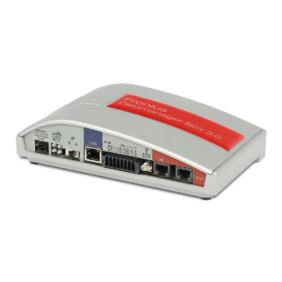
Page 19: Controls, Connections And Indicators
Controls, connections and indicators Safety WARNING! Danger due to incorrect operation. This can result in severe personal injury and damage to property. ▶ Do not use the functions described here until you have fully read and under- stood the Operating Instructions. ▶... -
Page 20: Controls, Connections, And Indicators
Fronius IG Plus Fronius Galvo Fronius IG Plus V Fronius Symo Fronius IG Plus A Fronius Primo Fronius CL Fronius CL USA Fronius IG 300 - 500 (13) (8) (9) (11) (12) Function IP switch For changing the IP address:... - Page 21 The Fronius Datamanager 2.0 works with an assigned IP address dy- namic host configuration protocol (DHCP) The IP address can be set on the Fronius Datamanager 2.0 website. In the case of the Fronius Datamanager 2.0 plug-in cards, the IP switch is located underneath the LEDs and is separate in the case of the Fronius Datamanager Box 2.0.
- Page 22 Lights up green: there is an active connection within Fronius Solar Net Lights up red: there is an interrupted connection within Fronius Solar Net Does not light up: the Fronius Datamanager 2.0 is in secondary mode LAN Connection Ethernet interface with blue color marking for connecting the Ether-...
- Page 23 Switching capacity when supplied by the Fronius Datamanager 2.0 plug-in card: 3.2 W, 10.8/12.8 V in total for all four digital outputs 10.8 V: Fronius IG, Fronius IG Plus, Fronius IG Plus V, Fronius IG Plus A, Fronius CL, Fronius CL USA, Fronius IG 300–500 12.8 V:...
-
Page 24: Schematic Connection Of I/Os
DATCOM components (e.g., inverters, sensor cards) For the Fronius Datamanager 2.0 with Fronius Com Card function only! (for Fronius IG, Fronius IG Plus, Fronius IG Plus V, Fronius IG Plus A, Fronius CL, Fronius CL USA, Fronius IG 300–500 inverters) (12) - Page 25 Current limit Solar Net IN connection socket 115–230 V AC: Fronius IG, Fronius IG Plus, Fronius IG Plus V, Fronius IG Plus A, Fronius CL, Fronius CL USA, Fronius IG 300 - 500 12.8 V DC: Fronius Galvo, Fronius Symo, Fronius Primo...
- Page 26 12.8 V DC: Fronius Galvo, Fronius Symo, Fronius Primo...
-
Page 27: Technical Data
= 46 kOhm Switching capacity of digital outputs 3.2 W when supplied by the Fronius Datamanager 2.0 plug-in card Fronius IG, Fronius IG Plus, Fronius 10.8 V IG Plus V, Fronius IG Plus A, Fronius CL, Fronius CL USA, Fronius IG 300–... - Page 28 DATCOM component. If the green LED does not light up, the power supply unit available from Fronius should be inserted into the 12 V power supply connection socket of an external DATCOM component. Check the cable and plug connections if necessary.
-
Page 29: Installing Fronius Datamanager 2.0
Installing Fronius Datamanager 2.0... -
Page 31: Inserting Fronius Datamanager 2.0 Into An Inverter
Fronius Symo does not matter Fronius Primo does not matter If an ENS plug-in card is inserted in the ENS slot: insert the Fronius Datamanager 2.0 in the next slot to the right of the ENS slot. - Page 32 IMPORTANT! The next slot must be kept free. Never remove an existing ENS plug-in card.
-
Page 33: Installing And Connecting Wlan Antennas
Connect the antenna cable to the antenna socket on the Fronius Datamanager 2.0 plug-in card Run the antenna cable out through the DATCOM opening on the in-... -
Page 34: Fronius Ig Usa, Fronius Ig Plus Usa, Fronius Ig Plus V Usa: Installing And Connecting
Attach the lock washer and screw 0,9 Nm on the hex nut Screw on the antenna Fronius IG USA, Fronius IG Plus USA, Fronius IG Plus V USA: In- stalling and Con- necting Anten-... - Page 35 CAUTION! Danger of short circuit caused by loose metal parts from knockouts. Loose metal parts in the inverter may cause short circuits when the inverter is powered up. When removing knockouts, make sure that ▶ no loose metal parts fall into the inverter, ▶...
- Page 36 8 Nm 5.90 ft. lb. *Bending radius of the antenna cable: at least 25.4 mm/1 in. 0.9 Nm 8 in-lb...
-
Page 37: Installing Fronius Datamanager 2.0 In Fronius Solar Net
The Fronius Solar Net cable should only be inserted into the Fronius Solar Net IN connection socket (colored red). Installing In- Fronius IG, Fronius IG Plus, Fronius IG Plus V, Fronius IG Plus A, Fronius CL, verters with Fronius CL USA, Fronius IG 300–500: Fronius Datamanager 2.0... -
Page 38: Installing Fronius Datamanager Box 2.0 In Fronius Solar Net
If only one inverter with Fronius Datamanager 2.0 is linked to a PC: Fronius IG, Fronius IG Plus, Fronius IG Plus V, Fronius IG Plus A, Fronius CL, Fronius CL USA, Fronius IG 300 - 500: Insert the Fronius Solar Net termination plug into the Fronius Solar Net IN... - Page 39 Ethernet cable is not included in the scope of supply for the Fronius Datamanager 2.0/Fronius Datamanager Box 2.0 Connection between Fronius Datamanager 2.0 and PC via LAN or WLAN Insert the Ethernet cable into the LAN connection socket Insert the Ethernet cable into the PC/laptop or into a suitable network con-...
-
Page 40: Fronius Solar Net Cabling
DATCOM components will hereinafter be referred to as Fronius Solar Net clients. Fronius Solar The data connection for the Fronius Solar Net client is a 1:1 connection using 8- Net Client pin data cables and RJ-45 plugs. -
Page 41: Preassembled Data Cables
ISO/IEC 11801:2002 internationally TIA/EIA 568 for North America Rules for use of copper cables apply. Preassembled The following preassembled data cables are available from Fronius: data cables CAT5 cable 1 m ... 43,0004,2435 CAT5 cable 20 m ... 43,0004,2434 CAT5 cable 60 m ... 43,0004,2436 The cables listed above are 8-pin, 1:1 LAN network cables, shielded and twisted, including RJ 45 plugs. -
Page 42: Installing Fronius Datamanager 2.0 - Overview
IMPORTANT! Inverters Fronius IG, Fronius IG Plus, Fronius IG Plus V, Froni- us IG Plus A, Fronius CL, Fronius CL USA, and Fronius IG 300–500 must al- ways be located at the beginning or end of the Fronius Solar Net ring. - Page 43 Switch the device to service mode Inverter with Fronius Datamanager 2.0 plug-in card: Switch the IP switch on the Fronius Datamanager 2.0 plug-in card to pos- ition A Activate the WLAN access point via the Setup menu of the inverter...
-
Page 44: Starting For The First Time Via A Web Browser
To start Fronius Datamanager 2.0 for the first time, the Fronius Datamanager 2.0 plug-in card must be installed in the inverter, there must be a Fronius Datamanager Box 2.0 in the Fronius Solar Net ring. - Page 45 IMPORTANT! Inverters Fronius IG, Fronius IG Plus, Fronius IG Plus V, Froni- us IG Plus A, Fronius CL, Fronius CL USA, and Fronius IG 300–500 must al- ways be located at the beginning or end of the Fronius Solar Net ring.
- Page 46 Switch the device to service mode Inverter with Fronius Datamanager 2.0 plug-in card: Switch the IP switch on the Fronius Datamanager 2.0 plug-in card to pos- ition A Activate the WLAN access point via the Setup menu of the inverter...
- Page 47 If the Technician Wizard is not run, no specifications for power reduction are set. The Solar.web Wizard must be run. If necessary, run the Technician Wizard and follow the instructions Run the Solar.web Wizard and follow the instructions The Fronius Solar.web start page appears. The Fronius Datamanager 2.0 website opens.
-
Page 49: Establishing A Connection To Fronius Datamanager
Establishing a Connection to Froni- us Datamanager 2.0... -
Page 51: Connecting To Fronius Datamanager 2.0 Via A Web Browser
Connecting to Fronius Datamanager 2.0 via a Web Browser General The connection to Fronius Datamanager 2.0 via a web browser is suitable for ac- cessing current values with several PC users in a LAN (e.g., company networks, schools). For example, total and daily yields can be accessed and/or inverter comparisons can be made on the Fronius Datamanager 2.0 website. -
Page 52: Connecting To Fronius Datamanager 2.0 Via The Internet And Fronius Solar.web
You can also provide other users with guest access so that they can view your photovoltaic system, or you can make a comparison of several systems. Function Over- Fronius Datamanager 2.0 is connected to the internet (e.g., via a DSL router). view Fronius Datamanager 2.0 regularly logs on to Fronius Solar.web and sends its saved data every day. -
Page 53: Current Data, Services, And Settings On Fronius Datamanager
Current Data, Services, and Set- tings on Fronius Datamanager 2.0... -
Page 55: The Fronius Datamanager 2.0 Website
Contact Send feedback Settings menu Other setting options Login The setting options on the website of the Fronius Datamanager 2.0 depend on the user's authorization (see section Settings – Passwords on page 65). Log in with username and password: Select the user to log in. -
Page 56: Reset Password
Selected menu item Menu items in Settings The Meter and DSO Editor menu items are pro- menu tected by the service password. Other setting Other setting options are shown in the top right corner of the Fronius Dataman- options ager 2.0 website:... - Page 57 Software Operating Instructions Fronius Solar Channel Expand contents: The Real-time Data/Settings menu is hidden Display notifications Language: Set the language The Fronius Datamanager 2.0 website will appear in the language set for the browser itself or in the last selected language.
-
Page 58: Current Data In Fronius Datamanager 2.0
Current Data in Fronius Datamanager 2.0 Current Com- Several inverters in the same photovoltaic system can be compared in the cur- parison View rent Comparison View. The real-time inverter AC power is displayed as a percentage of the power from the solar module connected to the respective inverter (shown in a bar diagram). -
Page 59: Services - System Information
Services – System Information System Informa- The System Information page contains various information about the system. tion The following buttons are also available: “Datalogger restart” button Used to restart the datamanager/system monitoring “Reset to factory settings” button with the following selection options: “All settings except for the network”... -
Page 60: Services - Network Diagnostics
Services – Network Diagnostics Network Dia- The Services / Network diagnostics option contains functions that are useful for gnostics diagnosing and correcting network problems. Ping and traceroute commands can be executed. Ping command Used to determine whether or not a host is available and how much time a data transfer will take. -
Page 61: Services - Firmware Update
Firmware Up- Establish LAN connection between PC/laptop and Datamanager date via LAN Download the current firmware from the Fronius homepage Run the downloaded update file on the PC/laptop This will start a web server from which the Datamanager will download the required files. - Page 62 Open “Firmware update” under “Services” Select “Update via LAN” Enter the IP address of the PC/laptop Click on the “Run update” button The confirmation prompt for the update appears. Click on the “Yes” button The update starts and the progress is displayed as a bar and a percentage. Once the update has been carried out successfully, click on the “Apply/Save”...
-
Page 63: Services - Opening Wizards
Services – Opening Wizards Opening Wizards Under "Open Wizards," it is possible to re-open the Solar.web Wizard and the Technician Wizard and run these again. -
Page 64: Settings - General
Settings – General General You can enter the charge rate per kWh, the currency, and the expenses per kWh to calculate the yield under "Feed-in payment." The yield is shown in the current Total View. The date, hour, and minutes can be entered under "System time." Click on the "Synchronize"... -
Page 65: Settings - Passwords
Settings – Passwords General Access to Fronius Datamanager 2.0 is regulated by assigning passwords. Three different password types are available: the administrator password the service password the user password Passwords Administrator Password User name = admin The administrator password set during commissioning assigns the user read and write (configuration) access. -
Page 66: Settings - Network
The connection to the Datamanager (system monitoring) can then be established using the name instead of the IP address. For example: Host name = sample_system, Domain name = fronius.com. The Datamanager (system monitoring) can be reached via the address “sample_system.fronius.com”. - Page 67 The Datamanager (system monitoring) is used as the access point. The PC or smart device connects directly to the Datamanager (system monitoring). Con- necting to the internet is not possible.
-
Page 68: Settings - Fronius Solar.web
Fronius Solar.web is automatically sent as well. Memory capa- The Fronius Datamanager has a memory capacity of up to 5 years and 7 months city for a PV system with one inverter and a save interval of 15 minutes. - Page 69 Save interval = 15 minutes Logging points per day: 840 min Inverter logging points = = 56 15 min 1440 min Sensor Card logging = 96 points = 15 min Total logging points: Total logging points = (2 x 56) + (1 x 96) = 208 (2 x 56) ...
-
Page 70: Settings - Io Mapping
(DRM) You can adjust the pins for control via DRM here: IMPORTANT! To control an inverter via DRM the inverter has to have a Fronius DRM Interface (item number 4,240,005). Assembly and installation are described in the Installation Instructions of the Fronius DRM Interface. -
Page 71: Io Control
DRM8 ≤ 100% Normal operation without restriction on the Fronius DRM inter- face The values for Q can be adjusted in the UC Editor menu item. The nominal device output is always meant when referring to the inverter's re- mote control capability. -
Page 72: Settings - Load Management
Settings - load management General The outputs I/O 0 - I/O 3 can be used to control an actuator (e.g., relay, contact- or) via the load management function. A connected load can thus be controlled by assigning a power feed-dependent switch-on or switch-off point. -
Page 73: Settings - Push Service
This function can be used to export current and log data in different formats or with different protocols to an external server. Further information about the push service function can be found in the follow- ing Operating Instructions: http://www.fronius.com/QR-link/4204102152 42,0410,2152 Fronius Push Service... -
Page 74: Modbus Settings
Modbus Settings General From your web browser, you can use the Fronius Datamanager 2.0 website to ap- ply the Modbus connection settings which cannot be accessed via the Modbus protocol. Additional In- For additional information on the Modbus function, please see the following Op-... - Page 75 Setting a constant reactive power "Data output via Modbus" set to "RTU" If there is a Modbus energy meter (e.g., Fronius Smart Meter) configured under Settings/Meter in the system, it will not be possible to use the "RTU" setting. In this case, data output via Modbus will be deactivated automatically upon se- lection of "RTU."...
-
Page 76: Limit Control
"IP address" field To limit inverter control to one or more devices, enter the IP addresses of the devices which are permitted to send commands to Fronius Datamanager in this field. Multiple entries are separated by commas. Examples: one IP address: 98.7.65.4 –... -
Page 77: Settings - Inverter
Settings – Inverter Inverter The data for the Comparison View is defined in the "Inverter" menu. If the "visible" selection field is selected, the inverter is displayed in the Compar- ison View. -
Page 78: Settings - Fronius Sensor Cards
Settings – Fronius Sensor Cards Sensor Cards A specific channel name can be assigned to each sensor value of a Fronius Sensor Card/Box under "Sensor Cards" (e.g., Wind Speed). -
Page 79: Settings - Counter
(1b) Secondary meter If a Fronius Smart Meter was chosen as a secondary meter, a window will open to enter the “Description” (freely selectable) as well as a “Modbus address” field. A value is suggested automatically in the “Modbus address” field (next free address in the address range). -
Page 80: Connecting The Fronius Smart Meter To The Fronius Datamanager
IMPORTANT! With an S0 meter at the infeed point, the meter data are not displayed in Fronius Solar.web. This option is only provided for dynamic power reduction. The con- sumption values can be detected to a limited extent when feeding into the grid. - Page 81 Requirements for the S0 meter: Must meet standard IEC 62053-31 Class B Max. voltage: 15 V DC Max. current when ON: 15 mA Min. current when ON: 2 mA Max. current when OFF: 0.15 mA Recommended max. impulse rate of S0 meter: PV power kWp [kW] Max.
-
Page 82: Settings - Dno Editor
Settings – DNO Editor General In the "UC Editor" menu item, settings relevant to electricity retailers are made. An effective power limit in % and/or a power factor limit can be set. IMPORTANT! Settings in the "UC Editor" menu item may only be made by staff trained to do so! The service password must be entered for the "UC Editor"... -
Page 83: Connection Example
I/Os on the Fronius Datamanager 2.0 Loads (e.g., signal light, signal relay) The ripple control signal receiver and the Fronius Datamanager 2.0 plug are con- nected to one another using a 4-pin cable in accordance with the connection dia- gram. -
Page 84: Uc Editor - Aus - Demand Response Modes (Drm)
Example settings on the DSO Editor for two ripple control signal receiver: (1) Ef- fective power limitation, (2) Power factor limitation UC Editor – AUS IMPORTANT! To control an inverter via DRM the inverter has to have a Fronius – Demand Re- DRM Interface (item number 4,240,005). sponse Modes... -
Page 85: Uc Editor - Control Priorities
If no meter has been selected under the "Meter" menu item: max. power generated for the entire system If Fronius Smart Meter or S0 inverter has been selected under the "Meter" menu item: max. energy fed into the grid "Hard Limit" - If this value is exceeded, the inverter switches off within max. 5 seconds.
Need help?
Do you have a question about the Datamanager 2.0 and is the answer not in the manual?
Questions and answers