Fronius Smart Meter 63A-1 Operating Instructions Manual
Pv system monitoring
Hide thumbs
Also See for Smart Meter 63A-1:
- Operating instructions manual (32 pages) ,
- Quick manual (20 pages) ,
- Quick start manual (10 pages)
Table of Contents
Advertisement
Quick Links
/ Perfect Charging / Perfect Welding / Solar Energy
LEARN MORE WITH
OUR HOW-TO VIDEOS
www.youtube.com/FroniusSolar
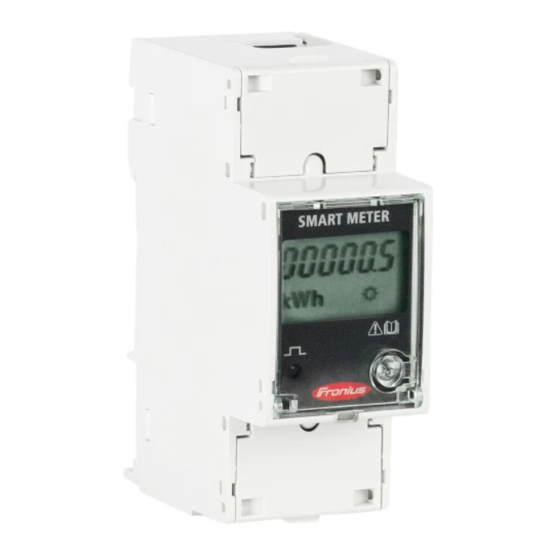
Fronius Smart Meter 63A-1
42,0426,0294,EN 006-19082020
Fronius prints on elemental chlorine free paper (ECF) sourced from certified sustainable forests (FSC).
Operating instructions
PV system monitoring
Advertisement
Table of Contents

Subscribe to Our Youtube Channel
Related Manuals for Fronius Smart Meter 63A-1


Summary of Contents for Fronius Smart Meter 63A-1
- Page 1 / Perfect Charging / Perfect Welding / Solar Energy LEARN MORE WITH OUR HOW-TO VIDEOS www.youtube.com/FroniusSolar Operating instructions Fronius Smart Meter 63A-1 PV system monitoring 42,0426,0294,EN 006-19082020 Fronius prints on elemental chlorine free paper (ECF) sourced from certified sustainable forests (FSC).
-
Page 3: Table Of Contents
Protective circuit Cabling Connecting the data communication cable to the inverter Terminating resistors Multi-meter system - Explanation of symbols Multi-meter system Setting the address of the Fronius Smart Meter Configuring the web interface Operation Menu structure Technical data Technical data... -
Page 4: Safety Rules
Safety rules General The device has been manufactured in line with the state of the art and according to recognized safety standards. If used incorrectly or misused, however, it can cause: Injury or death to the operator or a third party Damage to the device and other material assets belonging to the operating com- pany. -
Page 5: Copyright
Maintenance and repair work must only be carried out by an authorised specialist. It is impossible to guarantee that bought-in parts are designed and manufactured to meet the demands made on them, or that they satisfy safety requirements. Use only original spare parts (also applies to standard parts). -
Page 6: General
Indicates a risk of flawed results and possible damage to the equipment. Description of the The Fronius Smart Meter is a bidirectional electricity meter for optimising your own con- device sumption and recording the load curve of the household. Together with the Fronius Datamanager, the Fronius Smart Meter provides a clear overview of your own electricity consumption. -
Page 7: Positioning
Failure to comply with this EU Directive may result in a negative impact on the environment and your health! Positioning The Fronius Smart Meter can be installed at two possible locations in the system: at the feed-in point and at the consumption point. Placement at the feed-in point Fronius Smart Meter located at the feed-in point. -
Page 8: Installation
"Configuring the web interface" on page 14) Mounting The Fronius Smart Meter can be mounted on a 35 mm DIN rail. The housing comprises 2 modules according to DIN 43880 Protective circuit The Fronius Smart Meter is a hard-wired device and requires a disconnecting device (cir- cuit breaker, switch or disconnector) and overcurrent protection (automatic circuit breaker). -
Page 9: Cabling
Switch off the power supply before connecting the mains voltage inputs to the Fronius Smart Meter. Connecting the Connect the data communication connections of the Fronius Smart Meter to the Fronius data communica- system monitoring in the inverter. tion cable to the... -
Page 10: Terminating Resistors
▶ Use shielded twisted pair cables to avoid faults. ▶ The outputs of the Fronius Smart Meter are electrically isolated from hazardous voltages. Terminating res- Due to interference, it is recommended that terminating resistors are used as illustrated istors... - Page 11 * The terminating resistor on Fronius Smart Meters is installed between 33 and 34. The terminating resistor R 120 Ohm is included with the Fronius Smart Meter.
-
Page 12: Multi-Meter System - Explanation Of Symbols
Terminating resistor R 120 Ohm Multi-meter sys- If several Fronius Smart Meters are being installed, a separate address (see Setting the address of the Fronius Smart Meter page 13) must be set for each one. The... -
Page 13: Setting The Address Of The Fronius Smart Meter
1, all other meters are numbered in the address range from 2 to 14. Different types of Fronius Smart Meter can be used together. 0 0 1 0 0 1 0 0 1 0 0 1... -
Page 14: Configuring The Web Interface
Permissible values: 1 - 14 NOTE! Skip all other settings and leave them unchanged! How to configure the address of the Fronius Smart Meter in the Fronius Dataman- ager: Go to the Fronius Datamanager website. Open the web browser. In the address field, enter the IP address (IP address for WLAN: 192.168.250.181, IP address for LAN: 169.254.0.180) or the host and domain... - Page 15 Click on "Settings" (4) under primary meter. Set the position of the meter – feed-in point (1) or consumption point (2) – in the pop- up window. For more information on the position of the Fronius Smart Meter, see Positioning on page 7.
- Page 16 The Fronius Smart Meter is fully configured and ready for use. The "Current general view" menu item displays the power of the PV modules, self-con- sumption, the energy fed into the grid and the battery charge (if available).
-
Page 17: Operation
Operation Menu structure A graphic view of the menu structure can be found in the User Information that is sup- plied as standard. -
Page 18: Technical Data
Technical data Technical data Modbus transmission speed: 9600 baud Parity bit: None Software version: Datamanager 3.7.2 / Energypackage 1.3.3 Input Nominal voltage (1-phase) 230 V Operating range ±10% Self-consumption - voltage path (max. 4 VA (1.9 W) for 264 V voltage) Nominal frequency 50 - 60 Hz... -
Page 19: Fronius Manufacturer's Warranty
Wire (rigid) Min. 0.05 mm² / max. 4 mm² Wire (flexible) Min. 0.05 mm² / max. 2.5 mm² Recommended torque 0.5 Nm / max. 0.8 Nm Fronius manufac- Detailed, country-specific warranty terms are available on the internet: turer's warranty www.fronius.com/solar/warranty... - Page 20 To obtain the full warranty period for your newly installed Fronius inverter or storage sys- tem, please register at: www.solarweb.com.
- Page 24 FRONIUS INTERNATIONAL GMBH Froniusstraße 1 A-4643 Pettenbach AUSTRIA contact@fronius.com www.fronius.com Under www.fronius.com/contact you will find the addresses of all Fronius Sales & Service Partners and locations.
Need help?
Do you have a question about the Smart Meter 63A-1 and is the answer not in the manual?
Questions and answers