Table of Contents
Advertisement
/ Perfect Charging / Perfect Welding / Solar Energy
LEARN MORE WITH
OUR HOW-TO VIDEOS
www.youtube.com/FroniusSolar
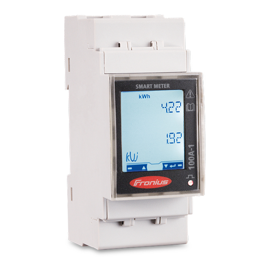
Fronius Smart Meter TS 100A-1
42,0426,0350,EN 007-22102020
Fronius prints on elemental chlorine free paper (ECF) sourced from certified sustainable forests (FSC).
Operating instructions
PV system monitoring
Advertisement
Table of Contents

Subscribe to Our Youtube Channel
Related Manuals for Fronius Smart Meter TS Series


Summary of Contents for Fronius Smart Meter TS Series
- Page 1 / Perfect Charging / Perfect Welding / Solar Energy LEARN MORE WITH OUR HOW-TO VIDEOS www.youtube.com/FroniusSolar Operating instructions Fronius Smart Meter TS 100A-1 PV system monitoring 42,0426,0350,EN 007-22102020 Fronius prints on elemental chlorine free paper (ECF) sourced from certified sustainable forests (FSC).
-
Page 3: Table Of Contents
Setting the address on the Fronius Smart Meter TS Start-up Fronius SnapINverter General Connecting to the Fronius Datamanager Configuring the Fronius Smart Meter TS as the primary meter Configuring the Fronius Smart Meter TS as a secondary meter Fronius GEN24 inverter General Installation using the web browser... -
Page 5: Safety Rules
Safety rules... -
Page 7: Safety Rules
Safety rules Explanation of DANGER! safety notices Indicates immediate danger. ▶ If not avoided, death or serious injury will result. WARNING! Indicates a potentially hazardous situation. ▶ If not avoided, death or serious injury may result. CAUTION! Indicates a situation where damage or injury could occur. ▶... -
Page 8: Environmental Conditions
The manufacturer accepts no liability for any deleted personal settings. Intended use The Fronius Smart Meter TS is a fixed piece of equipment for public grids of TN/TT sys- tems and records self-consumption and/or individual loads in the system. The Fronius Smart Meter TS is required for systems with a battery storage system and/or a Fronius Ohmpilot installed for communication between the individual components. -
Page 9: Information On The Device
The manufacturer shall not be liable for any damage resulting from such use. Reasonably foreseeable misuse: The Fronius Smart Meter TS is not suitable for the supply of life-sustaining medical devices or for the billing of subtenants. Information on Technical data, markings and safety symbols are located on the Fronius Smart Meter TS. - Page 10 RoHS (Restriction of Hazardous Substances) The limited use of certain hazardous substances in electrical and electronic equipment has been complied with in accordance with EU Directive 2011/65/EU. Safety symbols: Risk of serious injury and property damage due to incorrect operation. Dangerous electrical voltage.
-
Page 11: General Information
General information... -
Page 13: Fronius Smart Meter Ts 100A-1
Fronius Smart Meter TS 100A-1 Device descrip- The Fronius Smart Meter TS is a bidirectional electricity meter which optimises self-con- tion sumption and records the household's load curve. In conjunction with the Fronius inverter, Fronius Datamanager and Fronius data interface, the Fronius Smart Meter TS provides a clear overview of a user's own power consumption. -
Page 14: Scope Of Supply
2x seal wire 2x connection cover Fronius Smart Meter TS 65A-3 1x protective cover Quick Start guide Positioning The Fronius Smart Meter TS can be installed in the following positions in the system: Positioning at the feed-in point: Positioning at consumption point:... - Page 15 For use as a secondary meter to measure individual loads and producers, see chapter Multi-meter system on page 25.
-
Page 17: Installation
Installation... -
Page 19: Installation
(circuit breaker, switch or disconnector) and overcurrent‑protection (automatic‑circuit breaker). The Fronius Smart Meter TS consumes 10 - 30 mA, the nominal capacity of the discon- necting devices and the overcurrent‑protection is determined by the wire thickness, the mains voltage and the required breaking capacity. -
Page 20: Cabling
Disconnecting devices must be mounted within sight and as close as possible to the Fronius Smart Meter TS; they must also be easy to use. The disconnecting devices must satisfy the requirements of IEC 60947-1 and IEC 60947-3, as well as all national and local regulations for electrical systems. -
Page 21: Fitting The Protective Cover For The Terminals
Fit the protective cover properly and check that it is secure. Connecting the Connect the data communication connections of the Fronius Smart Meter TS to the Mod- data communica- bus interface of the Fronius inverter using a network cable (type CAT5 or higher). -
Page 22: Terminating Resistors - Explanation Of Symbols
Two wires can be installed in each terminal; the wires are twisted first, inserted into the terminal and tightened. Note: A loose wire can disable an entire area of the network. ▶ The data communication connections of the Fronius Smart Meter TS are electrically isolated from hazardous voltages. Terminating res- Inverter in the system istors - Explana- e. -
Page 23: Terminating Resistors
Terminating res- Due to interference, it is recommended that terminating resistors are used as illustrated istors below to ensure proper functioning. -
Page 24: Mounting The Connection Cover
* The terminating resistor is integrated in the Fronius Smart Meter TS and is manufac- tured with a bridge between the M and T connections (T = termination). Mounting the Insert the connection covers into the connection cover guides and press firmly. -
Page 25: Multi-Meter System
Terminating resistor R 120 Ohm Multi-meter sys- If several Fronius Smart Meter TS are installed, a separate address must be set for each (see Setting the address on the Fronius Smart Meter TS on page 27). The primary meter is always assigned address 1. -
Page 26: Menu Structure And Parameters
Only assign each Modbus address once. Terminating resistors must be positioned individually for each channel. For PV systems with inverters from the Fronius GEN24 and Fronius Tauro product series, the following must be observed: The primary meter and the battery must be connected to different channels. -
Page 27: Setting The Address On The Fronius Smart Meter Ts
Settings that need to be configured. Setting the Sym- Name Event Function address on the Fronius Smart Scroll one screen forward, increase the value by Meter TS Scroll one screen back, decrease the value by 1 Down/ Enter Call up settings, confirm value... - Page 28 Press and hold "Down/Enter" for 2 seconds. Press "Up" or "Down/Enter" to access the P1 screen. Set password "2633" with "Up" and "Down/Enter" and confirm each indi- vidual value with "Down/Enter". Note down the password. IMPORTANT! The password cannot be reset. Press "Up"...
-
Page 29: Start-Up
Start-up... -
Page 31: Fronius Snapinverter
The service password must be entered in order to access the "Meter" menu item. Three-phase or single-phase Fronius Smart Meter TS can be used. In both cases, the selection is made under the "Fronius Smart Meter" item. The Fronius Datamanager auto- matically identifies the meter type. -
Page 32: Configuring The Fronius Smart Meter Ts As A Secondary Meter
Enter the name of the secondary meter in the "Name" input field. Enter the previously assigned address in the “Modbus address” input field. Add meter description. Click the button to save the settings. The Fronius Smart Meter TS is configured as a secondary meter. -
Page 33: Fronius Gen24 Inverter
The service password must be entered in order to access the "System configuration" menu item. Three-phase or single-phase Fronius Smart Meter TS can be used. In both cases, the selection is made under the "Components" menu area. The meter type is determined automatically. -
Page 34: Configuring The Fronius Smart Meter Ts As The Primary Meter
Access the "Components“ menu area. Click the "Add component" button. In the "Position" drop-down list, set the position of the meter (feed-in point or con- sumption point). For more information on the position of the Fronius Smart Meter TS, Positioning on page 14. -
Page 35: Technical Data
Technical data Technical data Modbus transmission speed: 9600 baud Parity bit:none Software version: Fronius Datamanager 2.0 (from version 3.16.1 onwards) Fronius Symo Hybrid (from version 1.16.1 onwards) Measuring input Nominal voltage (1-phase) 230 V (-30% to +20%) Operating range Self-consumption - voltage path (max. -
Page 36: Fronius Manufacturer's Warranty
0.05 mm² Recommended torque max. 0.5 Nm Fronius manufac- Detailed, country-specific warranty terms are available on the internet: turer's warranty www.fronius.com/solar/warranty To obtain the full warranty period for your newly installed Fronius inverter or storage sys- tem, please register at: www.solarweb.com. - Page 40 FRONIUS INTERNATIONAL GMBH Froniusstraße 1 A-4643 Pettenbach AUSTRIA contact@fronius.com www.fronius.com Under www.fronius.com/contact you will find the addresses of all Fronius Sales & Service Partners and locations.
Need help?
Do you have a question about the Smart Meter TS Series and is the answer not in the manual?
Questions and answers