Table of Contents
Advertisement
Quick Links
Advertisement
Table of Contents

Related Manuals for Smartgen ACC7200


Summary of Contents for Smartgen ACC7200
- Page 1 ACC7200 DIESEL AIR COMPRESSOR CONTROLLER USER MANUAL...
- Page 2 Smartgen Technology at the address above. Any reference to trademarked product names used within this publication is owned by their respective companies. SmartGen Technology reserves the right to change the contents of this document without prior notice. Table 1 Software Version Date...
- Page 3 Indicates a procedure or practice, which, if not strictly observed, could result in CAUTION! damage or destruction of equipment. Indicates a procedure or practice, which could result in injury to personnel or loss of life if not followed correctly. WARNING! ACC7200 Air Compressor Controller User Manual Page 3 of 77...
-
Page 4: Table Of Contents
8.3 DEFINED CONTENTS OF DIGITAL INPUT PORTS 1-10 ............... 54 8.4 SELECTION OF SENSORS ......................56 8.5 CONDITIONS OF CRANK DISCONNECT SELECTION ..............57 9 PARAMETERS SETTING ........................57 9.1 MENU LIST ............................. 57 9.2 PARAMETER SETTING ........................58 ACC7200 Air Compressor Controller User Manual Page 4 of 77... - Page 5 14.15 SCANIA ............................74 14.16 VOLVO EDC3 ..........................74 14.17 VOLVO EDC4 ..........................75 14.18 VOLVO-EMS2 ..........................75 14.19 YUCHAI ............................76 14.20 WEICHAI ............................ 76 15 TROUBLE SHOOTING ......................... 77 ACC7200 Air Compressor Controller User Manual Page 5 of 77...
-
Page 6: Overview
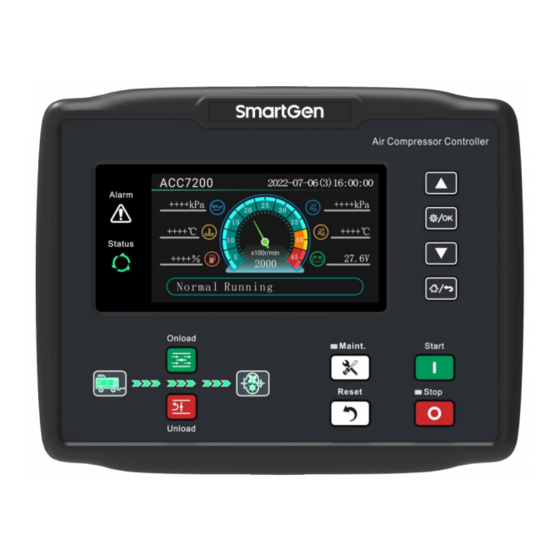
1 OVERVIEW ACC7200 Diesel Air Compressor Controller is used for air compressor with diesel-driven engine in order to realize functions of compressor start/stop, data measurement, maintenance, alarm protection and “three remotes”. It has speed regulator function, and CANBUS (SAE J1939) port, which can control various ECU or non-ECU diesel-driven air compressors. -
Page 7: Performance And Characteristics
IP65 and IP60 separately; — Wide operation temperature range (-30°C~+70°C), applicable for tough environment occasions; — Modular design, anti-flaming ABS shell, pluggable terminals, built-in mounting, compact structure and easy installation; ACC7200 Air Compressor Controller User Manual Page 7 of 77... -
Page 8: Specification
CE-EMC Certificate EN 55032、EN 55024 5Hz~8Hz: ±7.5mm Vibration 8Hz~500Hz: ±4g IEC 60068-2-6 50g, 11ms, half-sine, complete shock test from three directions, and 18 Shock times shock for each test IEC 60068-2-27 ACC7200 Air Compressor Controller User Manual Page 8 of 77... - Page 9 Back Panel: IP60 Apply AC2.2kV voltage between high voltage terminal and low voltage Insulation Intensity terminal and the leakage current is not more than 3mA within 1min. Weight 0.75kg. ACC7200 Air Compressor Controller User Manual Page 9 of 77...
-
Page 10: Operation
Confirm set information in parameter settings. Return to first page in main interface; Home/Return Return to last interface in parameter setting interface; NOTE: Press any key to mute the alarm in main interface. ACC7200 Air Compressor Controller User Manual Page 10 of 77... -
Page 11: Controller Panel
——Accumulative Information Page: current running time, total running time, start times and CPU temperature. ——Engine Status Information Page: current status of engine and onload status. ——Input/Output Status Page: emergency stop key and current status display of various digital ACC7200 Air Compressor Controller User Manual Page 11 of 77... -
Page 12: User Menu And Parameter Setting
The parameter setting include the following contents: ——Module Setting ——Timer Setting ——Engine Setting ——Air Compressor Setting ——Sensor Setting ——Input Port Setting ——Output Port Setting ——Optional Configuration Setting ——Maintenance Setting For example: ACC7200 Air Compressor Controller User Manual Page 12 of 77... - Page 13 (Interface 1). Interface 3: are used to change what need to be set, is used to enter the setting (Interface 4), is used to return the previous interface (Interface 2). ACC7200 Air Compressor Controller User Manual Page 13 of 77...
-
Page 14: Start/Stop Operaion
If air compressor crank disconnect fails during “Start Time”, then fuel relay and start relay stop outputting, and enter “Crank Rest Time”, waiting for next start; After the pre-set start attempts, if air compressor doesn't succeed to start, then controller issues ACC7200 Air Compressor Controller User Manual Page 14 of 77... -
Page 15: Stop Sequence
If output port is configured to “Fuel Pre-supply Output”, air compressor stays at standby status and it outputs cyclically according to the pre-set “Fuel Pre-supply Rest Time” and “Fuel Pre-supply Time”; If the pre-set “Fuel Pre-supply Rest Time” is 0h, then pre-supply doesn't output. ACC7200 Air Compressor Controller User Manual Page 15 of 77... -
Page 16: Emergency Start
Air Compressor onload speed: 70% (1540 r/min) Air Compressor unloading speed: 70% (1540 r/min) Air Compressor target pressure: 700kPa Air Compressor unloading action pressure: 600kPa Fig.2 Speed – Discharge Pressure Curve Diagram ACC7200 Air Compressor Controller User Manual Page 16 of 77... -
Page 17: Manual Dpf Regeneration
Configure an input port and set it to “DPF Manual Request”, and connect a button (not self-lock) externally. Press on controller panel and enter parameter setting menu. Press and select “DPF Regeneration”. Controller display is as Fig.3: Fig.3 DPF Regeneration Panel ACC7200 Air Compressor Controller User Manual Page 17 of 77... - Page 18 Fig.5 DPF Regeneration Start When manual regeneration is completed, DPF response indicator is light off, and DPF discharge temperature indicator is light off. Controller screen display is as Fig.3 shows. ACC7200 Air Compressor Controller User Manual Page 18 of 77...
-
Page 19: Protection
When controller detects discharge pressure value is below pre-set Warn pressure warning value, it issues warning signal. Discharge Temperature When controller detects discharge sensor is open and action type Open Warn is selected “Warning”, it issues warning signal. ACC7200 Air Compressor Controller User Manual Page 19 of 77... -
Page 20: Shutdown
When engine fails to start during pre-set start attempts, controller Failed to Start issues failed to start alarm signal. When controller receives shutdown alarm signal via J1939, it ECU Shutdown issues shutdown alarm signal. ACC7200 Air Compressor Controller User Manual Page 20 of 77... - Page 21 "Warning", it issues warning signal. Oil Filter Time Over When timing method is set to “Real Time Clock”, maintenance timing is due, and action type is selected “Shutdown”, it issues Oil Separator Time Over ACC7200 Air Compressor Controller User Manual Page 21 of 77...
- Page 22 NOTE: ECU warning and shutdown alarm instructions. If there is specific alarm display, please check the engine according to the content; otherwise, please refer to the engine manual for information according to SPN alarm code. ACC7200 Air Compressor Controller User Manual Page 22 of 77...
-
Page 23: Wiring Connection
7 WIRING CONNECTION The back panel of ACC7200 controller is as follows: Fig.6 Controller Back Panel ACC7200 Air Compressor Controller User Manual Page 23 of 77... - Page 24 AUX. Input 5 1.0mm Connects input COM. items. AUX. Input 6 1.0mm Connects input COM. AUX. Input 7 1.0mm Connects input COM. AUX. Input 8 1.0mm Connects input COM. ACC7200 Air Compressor Controller User Manual Page 24 of 77...
-
Page 25: Configuration Parameter Range And Definition
1: Enable LCD Backlight backlight Brightness (0-5) brightness. Compressor Lock Setting This password is used for entering Lock Set. Lock Password Set (0-65535) 01234 CAUTION: Default factory password is 01234; operator ACC7200 Air Compressor Controller User Manual Page 25 of 77... - Page 26 Please remember the password after the change, contact factory personnel in case of forgetting It is used for advanced Maintenance Password (0-65535) 01234 parameter settings; CAUTION: Default password ACC7200 Air Compressor Controller User Manual Page 26 of 77...
- Page 27 ( - ) interface; Default: Sum Fuel Used ( - ) Load Ratio ( - ) Torque Percent ( - ) Water In Fuel ( - ) Urea Level ( - ) ACC7200 Air Compressor Controller User Manual Page 27 of 77...
- Page 28 Time after idle running delay before complete stop when “ETS Output Time” is Wait Stop Time (0-3600)s set 0; When “ETS Output Time” is not 0, it is time after ETS delay before ACC7200 Air Compressor Controller User Manual Page 28 of 77...
- Page 29 Failed to Start signal. Please refer to Table 13. There are two kinds of Crank Disconnect Connections (0-2) disconnect conditions for engine and starter. They can be used independently ACC7200 Air Compressor Controller User Manual Page 29 of 77...
- Page 30 (0-3600)s issues charge fail warning. (0-100)% Urea Level Set value is urea level; Shutdown Return value and delay Delay (0-3600)s value can also be set. Urea Level Low Set (0-100)% ACC7200 Air Compressor Controller User Manual Page 30 of 77...
- Page 31 Decreased rotation number Overload Drop Speed (3-500)r/s per second. Rated speed percentage; After protection Overload Maint. Speed (0-100.0)% 70.0 overload, compressor will slow down; when it goes to maint. speed, will ACC7200 Air Compressor Controller User Manual Page 31 of 77...
- Page 32 This value is detected always. Delay Delay (0-3600)s value and return value can be set. When temp. sensor value Onload Inhibit Under Temp. (0-300)°C is lower than this value, ACC7200 Air Compressor Controller User Manual Page 32 of 77...
- Page 33 Delay Delay (0-3600)s value and return value can be set. When custom resistor/voltage/current is Custom Curve chosen in the curve type, corresponding curve shall be set. Flexible Sensor 1~8 Setting ACC7200 Air Compressor Controller User Manual Page 33 of 77...
- Page 34 Custom Curve types are selected; related curve needs to be set. Engine Temperature Related Setting 0: Not Used Sensor Correlate Set (0-8) 1: Flexible Sensor 1 2: Flexible Sensor 2 ACC7200 Air Compressor Controller User Manual Page 34 of 77...
- Page 35 Sensor Correlate Set (0-8) 4: Flexible Sensor 4 5: Flexible Sensor 5 6: Flexible Sensor 6 7: Flexible Sensor 7 8: Flexible Sensor 8 Over Shutdown Enable (0-1) 0: Disable 2: Enable ACC7200 Air Compressor Controller User Manual Page 35 of 77...
- Page 36 Max. Open (0-3600)min output. Time When the max. open time set as 0, output port works according to the open and close values, not limited by ACC7200 Air Compressor Controller User Manual Page 36 of 77...
- Page 37 Please refer to Table 12 for details. 0: Active for Close Active Type (0-1) 1: Active for Open 0: From Safety On 1: From Crank Active Range (0-3) 2: Always 3: Inactive ACC7200 Air Compressor Controller User Manual Page 37 of 77...
- Page 38 Users defined; For details Contents Setting (0-53) see Table 12. 0: Active for Close Active Type (0-1) 1: Active for Open 0: From Safety On Active Range (0-3) 1: From Crank ACC7200 Air Compressor Controller User Manual Page 38 of 77...
- Page 39 Input Description Users defined. Digital Input 10 Users defined; Contents Setting (0-53) Please refer to Table 12 for details. Active Type (0-1) 0: Active for Close ACC7200 Air Compressor Controller User Manual Page 39 of 77...
- Page 40 Normal running output; Contents Setting (0-139) Please refer to Table 11 for details. 0: Normally Open Output Type (0-1) 1: Normally Close Auxiliary Output 6 Contents Setting (0-139) Common alarm; ACC7200 Air Compressor Controller User Manual Page 40 of 77...
- Page 41 0: Load Control; 1: Load Control 1 Onload Output Selection (0-3) 2: Load Control 2 3: Load Control 3 Alt Config. 1 Rated Speed Overload Maint. Speed (0-100.0)% 70.0 percentage; ACC7200 Air Compressor Controller User Manual Page 41 of 77...
- Page 42 Alt Config. 3 Rated Speed percentage; After overload protection, Overload Maint. Speed (0-100.0)% 70.0 air compressor will slow down, and when it goes to maint. speed, it will keep the speed. ACC7200 Air Compressor Controller User Manual Page 42 of 77...
- Page 43 Maint. Time Due real-time clock. Air Filter Maintenance Setting Enable Set (0-1) 0: Disable; 1: Enable 0: No Act; 1: Warning (0-3) Maint. Set 2: Shutdown 3: Indication Set Value (0-30000)h ACC7200 Air Compressor Controller User Manual Page 43 of 77...
- Page 44 0: No Act; 1: Warning (0-3) Maint. Pre-warn 2: Shutdown 3: Indication Set Value (0-30000)h 0: Unit running time 1: Real-time Clock Maint. Timing Set (0-2) 2: Running time+ Real-time Clock ACC7200 Air Compressor Controller User Manual Page 44 of 77...
- Page 45 Timing the set date of the Maint. Time Due real-time clock. Maintenance 8 Setting Enable Set (0-1) 0: Disable; 1: Enable 0: No Act; 1: Warning Maint. Set (0-3) 2: Shutdown 3: Indication ACC7200 Air Compressor Controller User Manual Page 45 of 77...
- Page 46 3: Indication Set Value (0-30000)h 0: No Act; 1: Warning (0-3) 2: Shutdown Maint. Pre-warn 3: Indication Set Value (0-30000)h 0: Unit running time Maint. Timing Set (0-2) 1: Real-time Clock ACC7200 Air Compressor Controller User Manual Page 46 of 77...
- Page 47 Maint. Time Due real-time clock. — After ACC7200 using USB, the USB protective rubber cap shall be restored to its original state, so as to achieve better dust-proof and water-proof effect. — Regarding parameter setting on PC software, it isn't needed to input default factory password “01234” if it is not changed;...
-
Page 48: Defined Contents Of Auxiliary Output Ports 1-10
When the max. open time set as 0, output port works according to the open and close values, not limited by the max. open time. ACC7200 Air Compressor Controller User Manual Page 48 of 77... - Page 49 Common Alarm Act at the time of common alarm and common shutdown. Common Shutdown Act at the time of common shutdown. Common Warning Act at the time of common warning. Reserved ACC7200 Air Compressor Controller User Manual Page 49 of 77...
- Page 50 Low Temp Warning Act when low temp. warning alarm occurs. High Temp Shutdown Act when high temp. shutdown alarm occurs. Reserved Engine Low OP Warn Act when low oil pressure warning occurs. ACC7200 Air Compressor Controller User Manual Page 50 of 77...
- Page 51 Act when sensor 6 high warning occurs. 122 Flexible Sensor 6 Low Warn Act when sensor 6 low warning occurs. 123 Flexible Sensor 6 High Shut Act when sensor 6 high shutdown occurs. ACC7200 Air Compressor Controller User Manual Page 51 of 77...
-
Page 52: Custom Period Output
When input port 1 is active, and it enters start time and delays for 2s, custom period output starts to output, after outputting for 3s, it stops outputting; When input port 1 is inactive, custom output doesn't output. ACC7200 Air Compressor Controller User Manual Page 52 of 77... -
Page 53: Defined Combination Output
If input port 3 is inactive, defined combination output is not outputting; When input port 1 is inactive and port 2 is inactive, no matter port 3 is active or not, defined combination output is not outputting. ACC7200 Air Compressor Controller User Manual Page 53 of 77... -
Page 54: Defined Contents Of Digital Input Ports 1-10
ECU. Available for CUMMINS_QSG12 and used for DPF DPF Regeneration Test Mode Regeneration Mode testing Reserved Reserved Alarm Stop Inhibit All shutdown alarms are inhibited except emergency ACC7200 Air Compressor Controller User Manual Page 54 of 77... - Page 55 Act between start idle speed and stop idle speed; When it is active, speed reaches load speed, load control Load Input outputs; When it is inactive, load control stops outputting. Reserved Reserved Reserved Reserved Reserved Reserved ACC7200 Air Compressor Controller User Manual Page 55 of 77...
-
Page 56: Selection Of Sensors
6: Reserved If pre-set sensor channel 7: 0-130Ω doesn't support current, 8:10-180Ω and voltage type, then 9: 240-33Ω curve type item 2 and 3 10: 70-10Ω display “Reserved”. 11-15 Reserved ACC7200 Air Compressor Controller User Manual Page 56 of 77... -
Page 57: Conditions Of Crank Disconnect Selection
The menu list is as below: Parameters Set Lock Set Override Mode DPF Regeneration Language LCD Backlight Event Log Black Box Module Info ACC7200 Air Compressor Controller User Manual Page 57 of 77... -
Page 58: Parameter Setting
Programmable inputs 1-10 can’t be set as the same item, otherwise it won’t arise valid function. But programmable outputs 1-10 can be set the same. ACC7200 Air Compressor Controller User Manual Page 58 of 77... -
Page 59: Lock Setting
This interface displays the language of simplified Chinese, English and others; other languages default to the traditional Chinese. 9.7 LCD BACKLIGHT SETTING To set the brightness of the LCD backlight. ACC7200 Air Compressor Controller User Manual Page 59 of 77... -
Page 60: Event Log
In the specific record page, can directly switch pages and return to the event log page, press can also return to the event log page. ACC7200 Air Compressor Controller User Manual Page 60 of 77... -
Page 61: Black Box Record
50s before the event occurs at the earliest and 10s after the event occurs at the latest. Press in the details page to return to the black box record page. ACC7200 Air Compressor Controller User Manual Page 61 of 77... -
Page 62: Controller Information
It is applicable to set the headmost and backmost values in the vertical coordinate as the same as the Figure 7. Fig.7 Sensor Curve Setting ACC7200 Air Compressor Controller User Manual Page 62 of 77... -
Page 63: Commissioning
If everything goes well, engine will go to normal running after idle speed (if idle running is set). During this time, please observe engine’s running situation. If there is any other question, please contact SmartGen’s service. —... -
Page 64: Typical Application
12 TYPICAL APPLICATION Fig.8 ACC7200 Typical Application Diagram ACC7200 Air Compressor Controller User Manual Page 64 of 77... -
Page 65: Installation
Unit: mm Fig.9 Overall & Cutout Dimensions ACC7200 controller can suit battery voltage environment of DC(8~35)V. Negative of battery must be connected with the engine shell. Diameter of wire which connects power supply B+ and B- with battery positive and negative must be over 2.5mm . - Page 66 (when relay coils have DC current) or, increase resistance-capacitance return circuit (when relay coils have AC current), in order to prevent disturbance to the controller or other equipment. ACC7200 Air Compressor Controller User Manual Page 66 of 77...
-
Page 67: Connections Of Controller With J1939 Engine
Remark communication shielding line SAE J1939 shield-E (connect with ECU terminal only). CAN(H) SAE J1939 signal-C Using impedance 120Ω connecting line. CAN(L) SAE J1939 return-D Using impedance 120Ω connecting line. ACC7200 Air Compressor Controller User Manual Page 67 of 77... -
Page 68: Cummins Qsm11 (Import)
Remark communication shielding line SAE J1939 shield-E (connect with ECU terminal only). CAN(H) SAE J1939 signal-C Using impedance 120Ω connecting line. CAN(L) SAE J1939 return-D Using impedance 120Ω connecting line. ACC7200 Air Compressor Controller User Manual Page 68 of 77... -
Page 69: Cummins Gcs-Modbus
AUX. Output 2 is configured as “28: Starting Relay Output” (The configuration is factory default). Connect with starter coil directly. CAN communication shielding wire. CAN(H) Using impedance 120Ω connecting line. CAN(L) Using impedance 120Ω connecting line. ACC7200 Air Compressor Controller User Manual Page 69 of 77... -
Page 70: Cummins Qsz13
Starting Relay Output” (The configuration is factory default). Connect to starter coil directly. CAN communication shielding wire. CAN(H) CAN(H) Using impedance 120Ω connecting line. CAN(L) CAN(L) Using impedance 120Ω connecting line. ACC7200 Air Compressor Controller User Manual Page 70 of 77... -
Page 71: Deutz Emr2
Auxiliary Output 2 AUX. Output 2 is configured as “28: Starting Relay Output” (The configuration is factory default). CAN(H) Using impedance 120Ω connecting line. CAN(L) Using impedance 120Ω connecting line. ACC7200 Air Compressor Controller User Manual Page 71 of 77... -
Page 72: Mtu Mdec
Table 33 ADEC (X4 Port) Terminals of controller SMART (X4 port) Remark X4 3 CAN communication shielding wire. CAN(H) X4 1 Using impedance 120Ω connecting line CAN(L) X4 2 Using impedance 120Ω connecting line. ACC7200 Air Compressor Controller User Manual Page 72 of 77... -
Page 73: Mtu Adec (Sam Module)
AUX. Output 2 is configured as “28: Starting Relay Output” (The configuration is factory default). Connect to starter coil directly. CAN(H) Using impedance 120Ω connecting line. CAN(L) Using impedance 120Ω connecting line. ACC7200 Air Compressor Controller User Manual Page 73 of 77... -
Page 74: Scania
Remark CAN(H) Using impedance 120Ω connecting line. CAN(L) Using impedance 120Ω connecting line. NOTE: When this engine type is selected, preheating time should be set to at least 3 seconds. ACC7200 Air Compressor Controller User Manual Page 74 of 77... -
Page 75: Volvo Edc4
1(Hi) Using impedance 120Ω connecting line. CAN(L) 2(Lo) Using impedance 120Ω connecting line. NOTE: When this engine type is selected, preheating time should be set to at least 3 seconds. ACC7200 Air Compressor Controller User Manual Page 75 of 77... -
Page 76: Yuchai
Using impedance 120Ω connecting line. CAN(L) 1.34 Using impedance 120Ω connecting line. NOTE: If there is any question of connection between controller and ECU communication, please feel free to contact SmartGen’s service. ACC7200 Air Compressor Controller User Manual Page 76 of 77... -
Page 77: Trouble Shooting
If there is detailed alarm information, then check engine according to it; ECU warning or shutdown If there is not, refer to engine manual to obtain information according to SPN alarm code. _________________________________ ACC7200 Air Compressor Controller User Manual Page 77 of 77...
Need help?
Do you have a question about the ACC7200 and is the answer not in the manual?
Questions and answers