
Related Manuals for Smartgen ALC700 Series


Summary of Contents for Smartgen ALC700 Series
- Page 1 ALC700 SERIES (ALC704/ALC708) LIGHTING TOWER CONTROLLER USER MANUAL ZHENGZHOU SMARTGEN TECHNOLOGY CO.,LTD...
- Page 2 ALC700 Series Light Tower Set Controller 4 SPECIFICATION Parameter Details Working Voltage DC8. 0V to 35. 0V, uninterruptible power supply <5W (Standby mode: ≤2W) Overall Consumption Voltage Input: 3 Phase 4 Wire AC 20V - 360V (ph-N) 3 Phase 3 Wire...
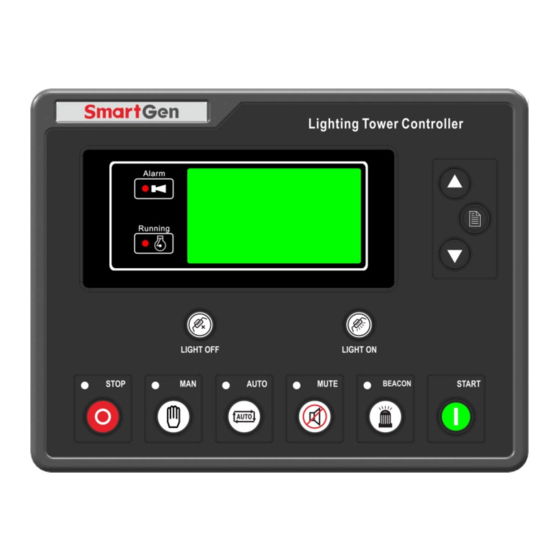
- Page 3 ALC700 Series Light Tower Set Controller 5 OPERATION 5.1 PUSHBUTTONS Icon Description Stop running light tower set; Stop/Reset Reset alarm when failure occurs; Lamp test in stop mode (press at least 3 seconds); Manual Mode Press this key and controller enters in Manual mode.
- Page 4 ALC700 Series Light Tower Set Controller 7 WIRING CONNECTION ALC700 controller’s rear as following: Description of terminal connection: Functions Cable Size Remark Connected with negative starter DC input B- 2.5 mm battery. Connected with positive of starter battery. DC input B+ 2.5 mm...
- Page 5 ALC700 Series Light Tower Set Controller TYPICAL WIRING DIAGRAMS ALC708 Typical Wiring Diagram Note: If 8 lights are all used, the maximum current of each light is 2A. ALC704 Typical Wiring Diagram Note: If 4 lights are all used, the maximum current of each light is 2A.
- Page 6 ALC700 Series Light Tower Set Controller DC Generator Typical Wiring Diagram NOTE: Users should select suitable Hall DC sensor according to the output power and current of the light tower set. INSTALLATION Controller is panel built-in design; it is fixed by clips when installed. The controller’s overall dimensions and cutout dimensions for panel, please refers to as following, 13.1 BATTERY VOLTAGE INPUT...
Need help?
Do you have a question about the ALC700 Series and is the answer not in the manual?
Questions and answers
What is the KPA for the generator
The oil pressure for the Smartgen ALC700 Series generator is 110 KPa.
This answer is automatically generated
I extended the light tower up and when I tried to lower it down the machine switched off and won’t start up again. Did the machine blow a fuse? What could be the problem ? Thank you