Advertisement
Quick Links
Advertisement

Subscribe to Our Youtube Channel
Related Manuals for Smartgen APC715N


Summary of Contents for Smartgen APC715N
- Page 1 APC715N ENGINE PUMP CONTROLLER USER MANUAL...
- Page 2 8.5 CONDITIONS OF CRANK DISCONNECT SELECTION ..............58 Table 17– Crank Disconnect Conditions Selection ................58 8.6 MAINTENANCE SETTING ......................59 9 SENSOR SETTING ..........................60 10 COMMUNICATION CONFIGURATION AND CONNECTION.............. 61 APC715N Engine Pump Controller User Manual Page 2 of 72...
- Page 3 13.8 SCANIA ............................68 13.9 VOLVO EDC3 ..........................69 13.10 VOLVO EDC4 ..........................69 13.11 VOLVO-EMS2 ..........................70 13.12 YUCHAI ............................70 13.13 WEICHAI ............................ 71 14 FAULT FINDING ..........................72 APC715N Engine Pump Controller User Manual Page 3 of 72...
- Page 4 All rights reserved. No part of this publication may be reproduced in any material form (including photocopying or storing in any medium by electronic means or other) without the written permission of the copyright holder. SmartGen reserves the right to change the contents of this document without prior notice. Table 1 – Software Version Date...
- Page 5 Indicates a procedure or practice, which, if not strictly observed, could result in CAUTION damage or destruction of equipment. Indicates a procedure or practice, which could result in injury to personnel or loss of WARNING life if not followed correctly. APC715N Engine Pump Controller User Manual Page 5 of 72...
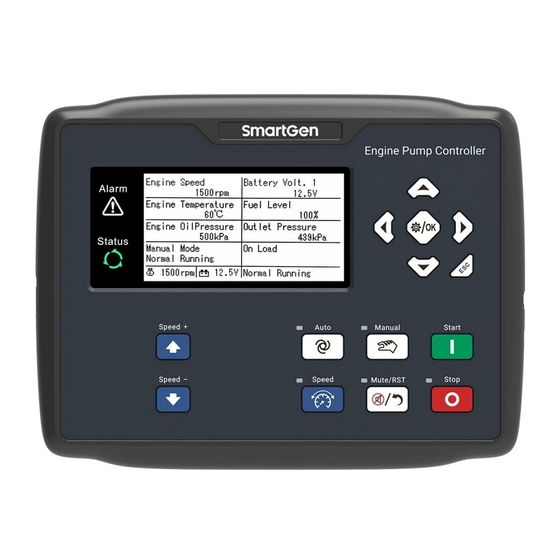
- Page 6 1 OVERVIEW APC715N Engine Pump Controller is used for diesel engine pump unit to realize the start/stop, speed regulation, data measurement, alarm protection and “four remotes” function of engine pump. It fits with LCD display, optional languages display (including Chinese, Englishes and other languages).
- Page 7 ——Can control engine heater, cooler and fuel pump; ——With maintenance function. Actions can be set when maintenance time out; ——All parameters used digital adjustment, instead of conventional analog modulation with normal potentiometer, improving reliability and stability; APC715N Engine Pump Controller User Manual Page 7 of 72...
- Page 8 ——IP65 due to rubber seal installed between the controller enclosure and panel fascia; ——Metal fixing clips enable perfect performance in high temperature environment; ——Modular design, anti-flaming ABS plastic enclosure, pluggable connection terminals and embedded installation mode; compact structure with easy mounting. APC715N Engine Pump Controller User Manual Page 8 of 72...
- Page 9 8 Hz ~ 100 Hz: 4 g Vibration 100Hz~500Hz: 2g IEC 60068-2-6 50g, 11ms, half-sine, complete shock test from three directions, Shock and 18 times shock for each test IEC 60068-2-27 Bump Test 25g, 16ms, half-sine APC715N Engine Pump Controller User Manual Page 9 of 72...
- Page 10 242mm x 186mm x 49mm Panel Cutout 214mm x 160mm Working Temperature (-25~+70)°C Working Humidity (20~93)%RH Storage Temperature (-30~+80)°C IP65, when water proof gasket ring inserted between panel and Protection Level housing. Weight 1.0kg APC715N Engine Pump Controller User Manual Page 10 of 72...
- Page 11 Fast Flashing ( 5 times per second) Shutdown Alarm Fast Flashing ( 5 times per second) No Alarm Extinguished Running Indicator: illuminated from crank success to ETS while off during other periods. APC715N Engine Pump Controller User Manual Page 11 of 72...
- Page 12 2. In setting menu, enter the next menu or confirm the set information. 1. Exit and return to the homepage; Exit 2. In setting menu, return to the previous menu. NOTE: Press any key to mute sound in main interface. APC715N Engine Pump Controller User Manual Page 12 of 72...
- Page 13 CAUTION: The default password is “00318”, operator can change it in case of others change the advanced parameter setting. Please clearly remember the password after changing. If you forget it, please contact SmartGen services and send all PD information in the controller page of “ABOUT” to us.
- Page 14 Displays the maintenance time and contents of 1~5 (if configured). ★Others: Time and date, input/output ports status, communication status, expand input/output ports status (if configured), Ethernet port configuration (if configured). ★About: APC715N Engine Pump Controller User Manual Page 14 of 72...
- Page 15 ——Digital Input Port Setting ——Digital Output Port Setting ——GOV Setting ——Gearbox Setting ——Scheduling and Maintenance Setting ——ECU Display Setting ——Network Communication Setting ——Expand Digital Input Setting ——Expand Digital Output Setting ——Expand AIN8 Setting APC715N Engine Pump Controller User Manual Page 15 of 72...
- Page 16 > Safety On Time saved to the internal storage space. is used > tart Idle Time > Warming Up Time to exit settings menu. NOTE: Press to exit the setting directly during setting. APC715N Engine Pump Controller User Manual Page 16 of 72...
- Page 17 LCD (If pump unit stopped successfully after “Failed to Stop” alarm, it will enter “After stop time” and remove alarm); Pump unit is placed into its standby mode after its “After Stop Time”. APC715N Engine Pump Controller User Manual Page 17 of 72...
- Page 18 “Idle Run without Load”2: Only auto GOV enables: Start the pump unit manually, only in auto GOV mode, the idle running, high-speed running and loading/unloading will be switched according to the input port status. APC715N Engine Pump Controller User Manual Page 18 of 72...
- Page 19 CAN Adjust Speed: Control the ECU engine speed simply by using CAN interface. According to the different gain, stability, dead band and acceleration/deceleration rate to control the engine speed. APC715N Engine Pump Controller User Manual Page 19 of 72...
- Page 20 Configure an input port and set it to “DPF Regeneration Inhibition”, and connect a button or switch externally. Press on controller panel and enter into parameter setting menu. Press and select “Post-processing Panel”. Controller display is as Fig.2: APC715N Engine Pump Controller User Manual Page 20 of 72...
- Page 21 Fig.2. If regeneration needs to be stopped, press “DPF Regeneration Inhibition” key. When DPF regeneration inhibition is activated, DPF regeneration inhibition indicator is always illuminated. APC715N Engine Pump Controller User Manual Page 21 of 72...
- Page 22 Alarm detection range: after safety on and before ETS hold. Flexible Sensor 1~10 When the controller detects that the sensor is open circuit and the Open action selects “Warn”, it will initiate a warning alarm. APC715N Engine Pump Controller User Manual Page 22 of 72...
- Page 23 Alarm detection range: after safety on and before ETS hold. When the mandate time has expired and the action selects “Warn”, Authorization Time Due the controller will initiate a warning alarm. APC715N Engine Pump Controller User Manual Page 23 of 72...
- Page 24 After AIN8 module enables, when the controller cannot receive the AIN8 Comm Fail communication data and the failure action is set as “Warn”, the controller will initiate a warning alarm. APC715N Engine Pump Controller User Manual Page 24 of 72...
- Page 25 When the controller detects the sensor value is higher than the Flexible Sensor 1~10 max. set value, it will initiate a shutdown alarm. High Alarm detection range: according to the set range to detect. APC715N Engine Pump Controller User Manual Page 25 of 72...
- Page 26 After extension output module enables, when the controller cannot Extension Output receive the communication data and the failure action is set as Module Comm Fail “Shutdown”, the controller will initiate a shutdown alarm. APC715N Engine Pump Controller User Manual Page 26 of 72...
- Page 27 “Fault Idle”, it will initiate a fault idle alarm. PLC Function 1~20 Alarm detection range: according to the PLC function set range to detect. APC715N Engine Pump Controller User Manual Page 27 of 72...
- Page 28 “Indication”, it will initiate a fault idle PLC Function 1~20 alarm. Alarm detection range: according to the PLC function set range to detect. APC715N Engine Pump Controller User Manual Page 28 of 72...
- Page 29 2, rated 7A table 14 B+ power is supplied by terminal Aux. Output 4 1.5mm 2, rated 7A B+ power is supplied by terminal Aux. Output 5 1.5mm 2, rated 7A APC715N Engine Pump Controller User Manual Page 29 of 72...
- Page 30 GOV A(-) 0.5mm earth connected. ECU CAN L 0.5mm Impedance-120Ω shielding wire is recommended, its ECU CAN H 0.5mm single-end earthed. 120Ω matched resistance has already connected internally. ECU SCR APC715N Engine Pump Controller User Manual Page 30 of 72...
- Page 31 RS485-2 B(-) 0.5mm RJ45 interface, connected PC testing software to ETHERNET configure parameter or other monitoring platforms. USB-TYPE B interface, connected with PC testing software to configure parameter and upgrade program. APC715N Engine Pump Controller User Manual Page 31 of 72...
- Page 32 Time from remote start signal is Stop Delay (0-3600)s deactivated to stop the pump unit. Time of pre-powering heat plug Preheat Delay (0-3600)s before starter is powered up. APC715N Engine Pump Controller User Manual Page 32 of 72...
- Page 33 Rated Speed 1500 over/under/loading speed. Setting value is percentage of rated Engine Idle Set (0-100.0)% 60.0 speed. Stabilize the engine speed on the set value if idle running is APC715N Engine Pump Controller User Manual Page 33 of 72...
- Page 34 Volt. Warn less than the set value, it will send a Delay (0-3600)s warning signal of under voltage. Offer standard to judge battery under Bat 2 Rated Volt. (0-60.0)V 24.0 voltage. APC715N Engine Pump Controller User Manual Page 34 of 72...
- Page 35 Delay (0-3600)s warning signal. Analog Sensors Setting Flexible Sensor 1 0: Disable; 1: Temperature Sensor; 2: Pressure Sensor; Sensor Selection (0-5) 3: Level Sensor; 4: Flow Sensor; 5: Virbration Sensor. APC715N Engine Pump Controller User Manual Page 35 of 72...
- Page 36 Open Action (0-2) 1: Shutdown Alarm; 2: No action. Display Unit (0-3) 0:kPa;1:bar;2:psi; 3:MPa。 0: After Safety Delay; 1: Cranking Start; Alarm Detection Range (0-3) 2: Alaways; 3: After loading. APC715N Engine Pump Controller User Manual Page 36 of 72...
- Page 37 Shutdown when external sensor value is lower than this value. The (0-9000) % Low Shutdown delay value and “warn enable” can be Delay (0-3600)s set. High Warn Enable (0-1) Shutdown when external sensor APC715N Engine Pump Controller User Manual Page 37 of 72...
- Page 38 The delay Low Warn Return (0-9000) ℃ value, “warn enable” and return value can be set. Delay (0-3600)s Users should set the corresponding Custom Curve curve when select resistor curve type APC715N Engine Pump Controller User Manual Page 38 of 72...
- Page 39 Cooler Control than this value, the cooler control will Max. output. Open (0-3600)min Time Engine Oil Pressure 0: ECU; Signal Source (0-10) 1: Flexible Senosr 1; 2: Flexible Senosr 2; APC715N Engine Pump Controller User Manual Page 39 of 72...
- Page 40 0: Not used; 1: Flexible Senosr 1; 2: Flexible Senosr 2; Signal Source (0-10) 3: Flexible Senosr 3; 4: Flexible Senosr 4; 5: Flexible Senosr 5; 6: Flexible Senosr 6; APC715N Engine Pump Controller User Manual Page 40 of 72...
- Page 41 Enable (0-1) When configuration enables, in auto mode, if the pipe pressure is lower (0-9000)kPa Under Start than the setting value, the engine will Delay (0-3600)s start. Flow Setting APC715N Engine Pump Controller User Manual Page 41 of 72...
- Page 42 1: Open Digital Input Port 4 Content (0-53) User-defined. Details see table 15. Active Type (0-1) 0: Close; 1: Open 0: Fron safety on; Arming (0-3) 1: From crank; 2: Always APC715N Engine Pump Controller User Manual Page 42 of 72...
- Page 43 0: Not used; 1: Relay adjust speed; GOV Port Type (0-3) 2: GOV analog adjust speed; 3: CAN adjust speed. Relay Dead Band (0-10.0)% Relay auto speed control. Adjust Gain (0-100)% APC715N Engine Pump Controller User Manual Page 43 of 72...
- Page 44 1: Manual Mode; Mode 2: Last Mode. Gearbox Setting Speed Enabled (0-1) 0: Disable; 1: Enable. teeth number gearbox Flywheel Teeth (1-300.0) 118.0 flywheel. Rated Speed (0-6000)r/mi Offer standard gearbox APC715N Engine Pump Controller User Manual Page 44 of 72...
- Page 45 D+ Voltage (0-1) 1: ECU. Oil Temperature (0-1) 0: Not display; Fuel Temperature (0-1) 1: Display (When smart display is active and no data receiced will not Fuel Pressure (0-1) APC715N Engine Pump Controller User Manual Page 45 of 72...
- Page 46 Extension Output Port 1~16 (0-299) digital output ports of DOUT16B can be set. Expand AIN8 0: Disable; Enable (0-1) 1: Enable. 0: Warn; Comm Failed Act (0-4) 1: Shutdown Alarm; 2: No Act. APC715N Engine Pump Controller User Manual Page 46 of 72...
- Page 47 NOTE: The Aux. input ports cannot be set as the same item, otherwise, the correct functions will not be realized. But the Aux. output ports can be set as the same items. APC715N Engine Pump Controller User Manual Page 47 of 72...
- Page 48 Act in period of cranking to safety run. Reserved Pre-lubricate Act in period of pre-heating to safety run. Remote Control This port is controlled by RS485 communication (PC). Reserved Reserved APC715N Engine Pump Controller User Manual Page 48 of 72...
- Page 49 Act when battery 1 over voltage warning alarms. Battery 1 Low Volts Act when battery 1 low voltage warning alarms. Charge Alt Fail Act when charge failure warning alarms. Rerserved Rerserved APC715N Engine Pump Controller User Manual Page 49 of 72...
- Page 50 Act when expansion input port 16 is active. Rerserved Rerserved Rerserved Rerserved Battery 2 High Volts Act when battery 2 over voltage warning alarms. Battery 2 Low Volts Act when battery 2 low voltage warning alarms. APC715N Engine Pump Controller User Manual Page 50 of 72...
- Page 51 Act when configurable sensor 7 low warns. Config Sensor 7 High Shutdown Act when configurable sensor 7 high shuts down. Config Sensor 7 Low Shutdown Act when configurable sensor 7 low shuts down. APC715N Engine Pump Controller User Manual Page 51 of 72...
- Page 52 Act when AIN8 flexible sensor 6 low warns. AIN8 Sensor 7 High Shutdown Act when AIN8 flexible sensor 7 high shuts down. AIN8 Sensor 7 High Warn Act when AIN8 flexible sensor 7 high warns. APC715N Engine Pump Controller User Manual Page 52 of 72...
- Page 53 Output port 1 active, after enter “start time” and delay 2s, this defined period output is outputting, after 3s, stop outputting; Output port 1 inactive, defined output period is not outputting. APC715N Engine Pump Controller User Manual Page 53 of 72...
- Page 54 If input port 3 inactive, defined combination output is not outputting; When input port 1 inactive and input port 2 inactive, whatever input port 3 is active or not, defined combination output is not outputting. APC715N Engine Pump Controller User Manual Page 54 of 72...
- Page 55 (Switch to the speed (memory) before the idle speed). Reserved Reserved Reserved Manual Load Input In manual mode, when the input port is active, the unit will take APC715N Engine Pump Controller User Manual Page 55 of 72...
- Page 56 DPF regeneration is prohibited, the controller will send a DPF regeneration inhibit order to ECU. DPF Regeneration Test When input port is active, DPF regeneration request is simulated. Mode 46-5 Reserved APC715N Engine Pump Controller User Manual Page 56 of 72...
- Page 57 If the sensor cannot support the current 5: SGH type and voltage type, the No.2 and No.3 of 6: Reserved the curve types will display “Reserved”. 7: 0~130Ω 8: 10~180Ω APC715N Engine Pump Controller User Manual Page 57 of 72...
- Page 58 If pump unit without engine speed sensor, please don’t select corresponding items, otherwise, “start fail” or “loss speed signal” maybe caused. If pimp unit without oil pressure sensor, please don’t select corresponding items. APC715N Engine Pump Controller User Manual Page 58 of 72...
- Page 59 Timer Mode The maintenance timer mode. 1: Real Time Clock Reset Maintenance Reset maintenance alarm when Time maintenance time is due. The maintenance name are user-set. E.g. Description Change oil. APC715N Engine Pump Controller User Manual Page 59 of 72...
- Page 60 Table 19– Common Unit Pressure Conversion Table (Pa) kgf/cm (p/in .psi) 1.02x10 - 1x10 - 1.45x10 - 1kgf/cm 9.8x10 0.98 14.2 1bar 1x10 1.02 14.5 - - 1psi 6.89x10 7.03x10 6.89x10 APC715N Engine Pump Controller User Manual Page 60 of 72...
- Page 61 Please refer to APC715N COMMUNICATION PROTOCOL for details. 10.2 RS485 COMMUNICATION DESCRIPTION APC715N pump unit controller has two isolated RS485 communication ports, one of the two can monitor the RS485 LAN and the other one can connect with CMM366 series modules to realize the cloud monitoring.
- Page 62 The D-type USB communication port can connect with PC testing software to set parameters and upgrade the module software. Fig.7 – USB Connection Diagram 11 TYPICAL APPLICATION Fig.8 – Typical Application Diagram APC715N Engine Pump Controller User Manual Page 62 of 72...
- Page 63 Battery Voltage Input NOTE: APC715N controller can suit for widely range of battery voltage DC(8~35)V. Negative of battery must be connected with the engine shell soundly. The diameter of wire which from power supply to battery must be over 2.5mm If floating charger configured, please firstly connect output wires of charger to battery’s positive and negative directly,...
- Page 64 (when coils of relay have DC current) or, add resistance-capacitance return circuit (when coils of relay have AC current), in order to prevent disturbance to controller or others equipment. APC715N Engine Pump Controller User Manual Page 64 of 72...
- Page 65 3 pins data link connector Remark communication shielding line CAN GND (connect with ECU terminal only). Impedance 120Ω connecting line is CAN(H) recommended. Impedance 120Ω connecting line is CAN(L) recommended. Engine Type: CUMMINS-CM570. APC715N Engine Pump Controller User Manual Page 65 of 72...
- Page 66 CAN communication shielding line (connect CAN GND with controller’s this terminal only). Impedance 120Ω connecting line CAN(H) recommended. Impedance 120Ω connecting line CAN(L) recommended. Engine Type: CUMMINS-QSZ13. APC715N Engine Pump Controller User Manual Page 66 of 72...
- Page 67 CAN GND X4 3 (connect to controller’s this terminal only). CAN(H) X4 1 Impedance 120Ω connecting line is recommended. CAN(L) X4 2 Impedance 120Ω connecting line is recommended. Engine Type: MTU-ADEC。 APC715N Engine Pump Controller User Manual Page 67 of 72...
- Page 68 Connect to starter coil directly. communication shielding line CAN GND (connect with controller’s terminal only). Impedance 120Ω connecting line CAN(H) recommended. Impedance 120Ω connecting line CAN(L) recommended. Engine Type: SCANIA-S8. APC715N Engine Pump Controller User Manual Page 68 of 72...
- Page 69 Connected to negative of battery. communication shielding line CAN GND (connect with controller’s terminal only). Impedance 120Ω connecting line is CAN(H) recommended. Impedance 120Ω connecting line is CAN(L) recommended. Engine Type: VOLVO. APC715N Engine Pump Controller User Manual Page 69 of 72...
- Page 70 Connect to starter coil directly communication shielding line CAN GND (connect with controller’s this terminal only) Impedance 120Ω connecting line CAN(H) 1.35 recommended. Impedance 120Ω connecting line CAN(L) 1.34 recommended. APC715N Engine Pump Controller User Manual Page 70 of 72...
- Page 71 Impedance 120Ω connecting line CAN(L) 1.34 recommended. Engine Type: GTSC1。 NOTE: If there is any question about connection between controller and ECU communication, please feel free to contact Smartgen’s service. APC715N Engine Pump Controller User Manual Page 71 of 72...
- Page 72 Get information from LCD of alarm page; ECU warning or shutdown If there is detailed alarm, check engine according to description. If not, please refer to engine manual according to SPN alarm code. _________________________________ APC715N Engine Pump Controller User Manual Page 72 of 72...
Need help?
Do you have a question about the APC715N and is the answer not in the manual?
Questions and answers