
Related Manuals for Smartgen ALC404


Summary of Contents for Smartgen ALC404
- Page 1 ALC404 LIGHTING TOWER CONTROLLER USER MANUAL SMARTGEN (ZHENGZHOU) TECHNOLOGY CO.,LTD.
- Page 2 SmartGen Technology at the address above. Any reference to trademarked product names used within this publication is owned by their respective companies. SmartGen Technology reserves the right to change the contents of this document without prior notice. Table 1 - Version history Date...
- Page 3 ALC404 LIGHTING TOWER CONTROLLER USER MANUAL This user manual only suits for ALC404 controller. Table 2 - Notation Clarification Symbol Instruction Highlights an essential element of a procedure to ensure correctness. NOTE Indicates a procedure or practice, which, if not strictly observed, could result in damage or CAUTION destruction of equipment.
-
Page 4: Table Of Contents
ALC404 LIGHTING TOWER CONTROLLER USER MANUAL CONTENTS OVERVIEW ............................... 6 PERFORMANCE AND CHARACTERISTICS ..................6 SPECIFICATION............................9 OPERATION ............................10 PUSHBUTTONS ..........................10 CONTROLLER PANEL ......................... 11 LCD DISPLAY ..........................11 SCHEDULED START/STOP OPERATION ................... 14 4.4.1 SCHEDULED START MODE SELECT OPERATION .............. 14 4.4.2... - Page 5 ALC404 LIGHTING TOWER CONTROLLER USER MANUAL 7.19.1 CONDITIONS OF ENTERING INTO DEEP SLEEP MODE ..........68 7.19.2 EXIT DEEP SLEEP MODE METHOD .................. 68 PARAMETERS SETTING ........................69 SETTING MENU DESCRIPTION ....................69 PARAMETERS SETTING ......................69 CONTROLLER TIME CALIBRATION.................... 69 LANGUAGE SELECTION ......................
-
Page 6: Overview
ALC404 LIGHTING TOWER CONTROLLER USER MANUAL 1 OVERVIEW ALC404 Lighting Tower Controller, suits for both AC and DC light tower set, is used for automation and monitor control systems of single light tower unit (diesel/petrol genset) to achieve not only scheduled start/stop, sunrise and sunset start/stop, manual start/stop as well as start/stop genset via remote input port but also turn on/off the flashlights of the light tower in proper order. - Page 7 ─ ALC404 controller can control up to 4 lamps and 4 feedback indicators were be fitted on the panel. In addition, the turn on interval time between two lights can be set by users.
- Page 8 ALC404 LIGHTING TOWER CONTROLLER USER MANUAL ─ 99 pieces of event logs can be circularly stored and inquired on the spot; also can be print or be inquired via PC. ─ More kinds of curves of temperature, oil pressure, fuel level can be used directly and users can select ―User Configured‖...
-
Page 9: Specification
ALC404 LIGHTING TOWER CONTROLLER USER MANUAL 3 SPECIFICATION Table 3 – Technical Parameters Items Contents Working Voltage DC8. 0V to 35. 0V, uninterruptible power supply ≤0.2W ≤3W (Standby mode: ≤2W; Deep Sleep mode: Overall Consumption Gen./Mains Voltage Input: 3 Phase 4 Wire... -
Page 10: Operation
ALC404 LIGHTING TOWER CONTROLLER USER MANUAL 4 OPERATION PUSHBUTTONS Table 4 – Keys Description Icon Function Description Stop running light tower set; Reset alarms in stop mode; Stop/Reset Lamp test in stop mode (press at least 3 seconds); Quick stop in stopping process. -
Page 11: Controller Panel
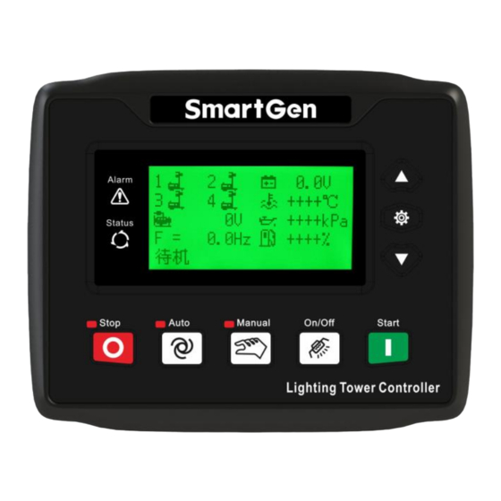
ALC404 LIGHTING TOWER CONTROLLER USER MANUAL CONTROLLER PANEL Fig.1 - ALC404 Front Panel NOTE: Partial indicators description, Alarm Indicator: slowly flash when warning alarms occur; fast flash when shutdown alarms occur; not illuminate if no alarms occur. Status Indicator: not illuminate while genset is standby; normally illuminate while genset is normal running. - Page 12 ALC404 LIGHTING TOWER CONTROLLER USER MANUAL Mains Screen Description Second screen display:Lighting tower set running Manual Mode status, current time, alarm information and etc. Manual Start Current Time 14:45:15 Gens Normal Running Generator Press button UL-L 399 399 399 V...
- Page 13 ALC404 LIGHTING TOWER CONTROLLER USER MANUAL Mains Screen Description Plant Battery 24.0 V Press button D+ Voltage 24.0 V The screen displays battery voltage, charger Engine Speed 1500 RPM 2017-11-23(4)14:46:00 voltage, engine speed of lighting tower set and current time of controller (the number in the parentheses is week information).
-
Page 14: Scheduled Start/Stop Operation
ALC404 LIGHTING TOWER CONTROLLER USER MANUAL SCHEDULED START/STOP OPERATION 4.4.1 SCHEDULED START MODE SELECT OPERATION Scheduled start operation has four modes to choose (00 daily, 01 weekly, 02 monthly and 03 custom week). The following content take the Scheduled Start (00 daily) as the example, and the other modes’... -
Page 15: Scheduled Start Operation Process
ALC404 LIGHTING TOWER CONTROLLER USER MANUAL Process Description Panel Display detailed setting navigation screen, and select Timer Running Action Return throught , and then press Return to return to Timer Running Action confirmation 01Timer Mode Selection screen. 02Auto Run Timer Set... -
Page 16: Sunrise/Sunset Start Operation
ALC404 LIGHTING TOWER CONTROLLER USER MANUAL Operation Process Panel Display Time Left 11:58:57 Start Time 18:30:00 Current Time 18:31:02 If engine speed, generator voltage and frequency has 3# Light On reached on-load requirements (speed ≥ on-load speed, voltage ≥ on-load voltage and frequency ≥ on-load... - Page 17 ALC404 LIGHTING TOWER CONTROLLER USER MANUAL Process Description Panel Display other city to re-read configuration, and then return back to the sunset/sunrise start screen to confirm that whether the city to be chosen is the one downloaded a moment ago or not.
-
Page 18: Sunrise/Sunset Start/Stop Operation Process
ALC404 LIGHTING TOWER CONTROLLER USER MANUAL Process Description Panel Display 04 Sunrise Time Delay CurrentVal +00000min +00000 Sunrise/set Action Return Select 01 Mode Start via key and 01 Mode Start press to confirm the action. Controller will jump to the 2... -
Page 19: Auto Remote Start/Stop Operation
ALC404 LIGHTING TOWER CONTROLLER USER MANUAL Operation Process Panel Display Stop Time 07:06:00 Start Time 16:55:00 Current Time 16:55:54 If engine speed, generator voltage and frequency has 2# Light On reached on-load requirements (speed ≥ on-load speed, voltage ≥ on-load voltage and frequency ≥ on-load... -
Page 20: Auto Remote Start/Stop Process Operation
ALC404 LIGHTING TOWER CONTROLLER USER MANUAL Process Description Panel Display Remote Start Mode Confirm Wait Remote Start Press to confirm remote start mode, and Current Time 17:30:00 remote start then controller will jump to the 2 page. Meanwhile, Standby mode remote start mode set completely. -
Page 21: Manual Start/Stop Operation
ALC404 LIGHTING TOWER CONTROLLER USER MANUAL Operation Process Panel Display Remote Start Mode Wait Remote Start Current Time 07:00:09 3# Light Off Remote Start Mode Wait Remote Start Current Time 07:00:15 Cooling Time Remark: The Remote start/stop mode will be canceled automatically when select other auto start mode!... - Page 22 ALC404 LIGHTING TOWER CONTROLLER USER MANUAL Operation Process Panel Display If light tower set high-speed warming up is over, Manual Mode meanwhile, engine speed, generator voltage and frequency Manual Start has reached on-load requirements (speed ≥ on-load speed, Current Time 17:00:58 voltage ≥...
-
Page 23: Force Start Operation
ALC404 LIGHTING TOWER CONTROLLER USER MANUAL FORCE START OPERATION Simultaneously pressing in manual mode can force start light tower set, at the moment, starter disconnect controlled by the operator instead of judging from crank disconnect conditions. When light tower set successfully start, operator will release the keys and controller enters into safety running delay. -
Page 24: Protections
ALC404 LIGHTING TOWER CONTROLLER USER MANUAL 5 PROTECTIONS WARNING ALARMS Warnings are not lead to light tower set shutdown and alarm information will be displayed on the LCD. Table 14 - Warning Alarms Type Description When controller detects the high temperature input is active, it will... - Page 25 ALC404 LIGHTING TOWER CONTROLLER USER MANUAL Type Description When controller detects the low fuel level warning input is active, it Low Fuel Level will send warning signal and the corresponding alarm information will be displayed on the LCD. If it is enabled, when controller detects the charger voltage of light...
- Page 26 ALC404 LIGHTING TOWER CONTROLLER USER MANUAL Type Description When controller receives engine warning alarm signals via J1939, it ECU Warning will send warning signal and corresponding alarm information will be displayed on the LCD. If it is enabled, when controller detects the coolant temperature transferred by EFI engine is higher than the maximum limit of preset ECU Coolant Temp.
-
Page 27: Shutdown Alarms
ALC404 LIGHTING TOWER CONTROLLER USER MANUAL SHUTDOWN ALARMS When controller detects shutdown alarm, it will send signal to turn off #1~#4 lights and shuts down generator and corresponding alarm information will be displayed on LCD. Table 15 - Shutdown Alarms... - Page 28 ALC404 LIGHTING TOWER CONTROLLER USER MANUAL Type Description If it is enabled, when controller detects the current is higher than the maximum limit of preset value, meanwhile, action select as shutdown, it Over Current will send a shutdown signal and the corresponding alarm information will be displayed on the LCD.
- Page 29 ALC404 LIGHTING TOWER CONTROLLER USER MANUAL Type Description If it is enabled, when controller detects the sensor 2 value is lower than the minimum limit of preset value, it will send shutdown signal and the Sensor 2 Low corresponding alarm information will be displayed on the LCD. If the sensor name is configured by users as xxx, then ―xxx Low‖...
- Page 30 ALC404 LIGHTING TOWER CONTROLLER USER MANUAL Type Description When controller detects the Coolant Level Low Shutdown input is active, Coolant Level Low it will send shutdown signal and the corresponding alarm information will be displayed on the LCD. When controller receives engine shutdown alarm signals via J1939, it will...
-
Page 31: Trip And Stop Alarms
ALC404 LIGHTING TOWER CONTROLLER USER MANUAL TRIP AND STOP ALARMS When the controller detects trip and stop signal, it will send signal to turn off #1~#4 lights and then generator cooling down and stop. Table 16 – Trip and Stop Alarms... -
Page 32: Wiring Connection
ALC404 LIGHTING TOWER CONTROLLER USER MANUAL 6 WIRING CONNECTION ALC404 controller’s rear is as following: Fig.2 - ALC404 Controller Rare Panel Diagram Table 17 - Terminal Connection Description Functions Cable Size Description DC power negative input and external connected DC input B- 1.5 mm... - Page 33 ALC404 LIGHTING TOWER CONTROLLER USER MANUAL Functions Cable Size Description of volt free relay; external connect with DC voltage. Aux. Output 4 1.0 mm Separately combined with terminal No. 8 as Aux. Output 5 1.0 mm normally open contactor of relay with rated current 1A (voltage free output).
-
Page 34: Scopes And Definitions Of Programmable Parameters
ALC404 LIGHTING TOWER CONTROLLER USER MANUAL 7 SCOPES AND DEFINITIONS OF PROGRAMMABLE PARAMETERS AUTO START PARAMETER SETTINGS Table 18 – Auto Start Parameter Settings Parameters Setting Range Default Remark 00 Daily 01 Weekly Timer Mode Select (0~3) 00 Daily 02 Monthly... -
Page 35: Generic Parameter Settings
ALC404 LIGHTING TOWER CONTROLLER USER MANUAL GENERIC PARAMETER SETTINGS Table 19 – Generic Parameter Settings Category Parameters Range Default Description It is time from remote start signal is active to genset Start Delay (0~3600)s started. It is time from remote start... - Page 36 ALC404 LIGHTING TOWER CONTROLLER USER MANUAL Category Parameters Range Default Description as 0, it is time from ETS solenoid hold expired to genset stop completely; It is audible alarm output Audible Alarm Time (1~3600)s time after the new alarm signal occurred.
- Page 37 ALC404 LIGHTING TOWER CONTROLLER USER MANUAL Category Parameters Range Default Description and loading speed. 0 Disabled 1 Enabled After fast loading enabled, engine starts and enters into stage of safety on Enable Fast Loading Feature (0~1) delay, and if genset meet...
- Page 38 ALC404 LIGHTING TOWER CONTROLLER USER MANUAL Category Parameters Range Default Description disconnect. Details to see the following installation instructions. When genset oil pressure is above the setting limit, Disconnect Oil Pressure (200~600)kPa 200 starter will disconnect. Details to see the following installation instructions.
- Page 39 ALC404 LIGHTING TOWER CONTROLLER USER MANUAL Category Parameters Range Default Description percentage of starting battery rated voltage Delay (0~3600)s Enable (0~1) 0 Disabled 1 Enabled The setting value is Set Value (0~200)% percentage of starting battery rated voltage Battery Over...
- Page 40 ALC404 LIGHTING TOWER CONTROLLER USER MANUAL Category Parameters Range Default Description exceeds full charged limit, controller will start trickle charging countdown. It is the time from controller detects battery under Under voltage start signal to Battery (0~3600)s genset starts up, or time...
- Page 41 ALC404 LIGHTING TOWER CONTROLLER USER MANUAL Category Parameters Range Default Description Note: this function is only active in safety running period. This moment, over speed shutdown delay is overshoot delay, and calculation formula of speed limit is speed limit=rated speed * over speed % * (1+overshoot %).
- Page 42 ALC404 LIGHTING TOWER CONTROLLER USER MANUAL Category Parameters Range Default Description DC Genset Check 0 3Phase, 4Wire(3P4W) AC Set 1 3Phase, 3Wire(3P3W) AC System (0~3) 2 1Phase, 2Wire(1P2W) 3 2Phase, 3Wire(2P3W) Note: if users select power supply type as 4 DC Power, meanwhile,...
- Page 43 ALC404 LIGHTING TOWER CONTROLLER USER MANUAL Category Parameters Range Default Description frequency, genset will not enter into normal running status. Enable (0~1) 0 Disabled 1 Enabled Voltage PT Primary (10~1000)V Transformer(PT) PT Secondary (10~1000)V Enable (0~1) 0 Disabled 1 Enabled The setting limit is Gen.
- Page 44 ALC404 LIGHTING TOWER CONTROLLER USER MANUAL Category Parameters Range Default Description Enable (0~1) 0 Disabled 1 Enabled The setting limit is Set Value (0~200)% percentage of generator rated frequency. Gen. Under Frequency Warning The setting limit is Return (0~200)% percentage of generator rated frequency.
- Page 45 ALC404 LIGHTING TOWER CONTROLLER USER MANUAL Category Parameters Range Default Description percentage of mains rated voltage. The setting limit is Return (0~200)% percentage of mains rated voltage. Delay (0~3600)s Enable (0~1) 0 Disabled 1 Enabled The setting limit is Set Value...
- Page 46 ALC404 LIGHTING TOWER CONTROLLER USER MANUAL Category Parameters Range Default Description load. Number of lights that the Light Amount Config. (1~4) system can control effectively. Rated current consumption for each light, which is used Single Light Rated Current (0.01~99.99)A 4.00 to provide standard for judging light fault.
- Page 47 ALC404 LIGHTING TOWER CONTROLLER USER MANUAL Category Parameters Range Default Description max. number of turned on lights that allowed to number of lights that allowed in this mode. While genset is normal running, when fuel level exceeds the setting limit...
- Page 48 ALC404 LIGHTING TOWER CONTROLLER USER MANUAL Category Parameters Range Default Description (0~3600)s Delay (0~1) Enable 0 Disabled 1 Enabled (0~1000)kPa Value Warning Return (0~1000)kPa Value (0~3600)s Delay NOTE: Parameters of ECU_coolant temperature and ECU_oil pressure, only available for EFI genset, are used for judging alarm situation of coolant temperature and oil pressure that returned from ECU.
- Page 49 ALC404 LIGHTING TOWER CONTROLLER USER MANUAL Category Parameters Range Default Description 0 Open Output Type (0~1) 0 Open 1 Close 7.11 FUNCTION Function 22 Common (0~119) DEFINITION OF OUTPUT Config. Shutdown Output 3 Set PORTS. 0 Open Output Type (0~1)
-
Page 50: Flexible Sensor 1 Settings
ALC404 LIGHTING TOWER CONTROLLER USER MANUAL Category Parameters Range Default Description Delay pressed before the delay expired is one condition for judging whether controller enters into deep sleep mode. NOTE: The remaining parameters can only be configured by the PC software. -
Page 51: Flexible Sensor 2 Settings
ALC404 LIGHTING TOWER CONTROLLER USER MANUAL Parameter Range Default Description point X follows: (0~1000) (Resistance) pressure type: kPa point X Fuel level type: % (0~1000) (Resistance) Temperature type: ℃ point X (0~1000) (Resistance) point X (0~1000) (Resistance) point X (0~1000) - Page 52 ALC404 LIGHTING TOWER CONTROLLER USER MANUAL Parameter Range Default Description Enable (0~1) 0 Disabled 1 Enabled Sensor Low Set Value (0~1000)kPa Shutdown Delay (0~3600)s Enable (0~1) 0 Disabled 1 Enabled Set Value (0~1000)kPa Sensor High Warning Return Value (0~1000)kPa Delay...
-
Page 53: Flexible Sensor 3 Settings
ALC404 LIGHTING TOWER CONTROLLER USER MANUAL FLEXIBLE SENSOR 3 SETTINGS Table 22 – Flexible Sensor 3 Settings Parameter Range Default Description 0 Not Used 1 Temp. Sensor Sensor Type (0~3) 2 Pressure Sensor 3 Fuel Level Sensor Details of sensor curve... -
Page 54: Sensor Curve Selection
ALC404 LIGHTING TOWER CONTROLLER USER MANUAL Parameter Range Default Description point X (0~1000) (Resistance) point Y(Value) (0~4000) point Y(Value) (0~4000) point Y(Value) (0~4000) point Y(Value) (0~4000) point Y(Value) (0~4000) point Y(Value) (0~4000) point Y(Value) (0~4000) point Y(Value) (0~4000) Chinese:燃油液 User-defined PC software can write 10 位... - Page 55 ALC404 LIGHTING TOWER CONTROLLER USER MANUAL Items Content Remark 9 SGX 10 bar 10 CMB812 11 SGH 10 bar 12 Curtis 13 SGD 10 bar 14 Reserved 15 Reserved 0 Not Used 1 Digital close for low fuel level 2 Digital open for low fuel level...
-
Page 56: Sensor Setting
ALC404 LIGHTING TOWER CONTROLLER USER MANUAL SENSOR SETTING When reselect sensors, the sensor curve will be transferred into the standard value. For example, if factory default set as temperature sensor is SGX (120° C resistor type), its sensor curve is SGX (120° C resistor type);... -
Page 57: Conditions Of Crank Disconnect Selection
ALC404 LIGHTING TOWER CONTROLLER USER MANUAL CONDITIONS OF CRANK DISCONNECT SELECTION Table 25 – AC Generator Crank Disconnect Conditions Contents Gen frequency Speed Speed + Gen frequency Oil pressure Oil pressure + Gen frequency Oil pressure + Speed Oil pressure + Speed + Gen frequency Table 26 –... -
Page 58: Function Definition Of Input Ports
ALC404 LIGHTING TOWER CONTROLLER USER MANUAL FUNCTION DEFINITION OF INPUT PORTS Table 27 – Functions of Input Ports Type Description Not Used Alarm types can be set by users. Details of setting content please to User Configured see 7.10 DEFINITION OF PROGRAMMABLE INPUT PORTS 1-5. - Page 59 ALC404 LIGHTING TOWER CONTROLLER USER MANUAL Type Description Shutdown immediate shutdown and controller initiate shutdown alarms. If the signal is active after safety on delay expired, genset will Low Fuel Level Shutdown immediate shutdown and controller initiate shutdown alarms. Low Coolant Level...
-
Page 60: Definition Of Programmable Input Port 1-5
ALC404 LIGHTING TOWER CONTROLLER USER MANUAL Type Description Reserved Reserved Reserved When the input port is active, controller's power harvesting port Mains Supply Active detects mains voltage, and controller controls lighting tower follows the logic of mains supply. NOTE: The user-defined names of input port 1~5 can be set only via PC software. -
Page 61: Enable Definition Of Programmable Output Port
ALC404 LIGHTING TOWER CONTROLLER USER MANUAL 7.11 ENABLE DEFINITION OF PROGRAMMABLE OUTPUT PORT Table 29 - Definition of Output Ports Type Description Not Used Action when over speed shutdown and emergence stop. It also Air Flap Relay can close the air inflow to stop the engine as soon as possible. - Page 62 ALC404 LIGHTING TOWER CONTROLLER USER MANUAL Type Description occurs. Action when genset common warning, common shutdown, Common Alarm common trips alarm. Common Trip and Stop Alarm Action when common trips alarms occur. Common Shutdown Alarm Action when common shutdown alarms occur.
- Page 63 ALC404 LIGHTING TOWER CONTROLLER USER MANUAL Type Description Active when the voltage falls below the Under Voltage Warning Gen. Under Volt. Warning setting Active when the voltage falls below the Under Voltage Gen. Under Volt. Shutdown Shutdown setting Action when genset cranking and disconnect when genset Louver Control stopped completely.
- Page 64 ALC404 LIGHTING TOWER CONTROLLER USER MANUAL Type Description Preheat (until end of safety on) Action in period of preheat delay to the end of safety on delay. Cooling Timer In Process Action in period of cooling delay. Reserved System In Auto Mode Action when system is in Auto mode.
-
Page 65: Over Current Action
ALC404 LIGHTING TOWER CONTROLLER USER MANUAL Type Description Active when the generator is shutdown due to sensor 2 is too Sensor 2 Low Shutdown low. Active when the generator is warning due to sensor 3 is open Sensor 3 Open Circuit Warning... -
Page 66: Light Input Control Mode
7.13 LIGHT INPUT CONTROL MODE ALC404 controller can define light input port as 3 modes: Feedback input, Control input and major control input. After genset entering into normal running stage and for the light that configured as feedback input mode, controller automatically controls the output of the light according to the control logic, and the indicator on the panel shows the light on/off based on the light input port status. -
Page 67: Timer Mode Select
ALC404 LIGHTING TOWER CONTROLLER USER MANUAL battery damaged and cannot been full charged, controller will force the unit to stop after the pre-set maximum Under Voltage Charging Time to prevent accidents. The work mode can be set as Invalid, Auto Mode Active, Manual Mode Active, Auto And Manual Mode Active. -
Page 68: Deep Sleep Mode
ALC404 LIGHTING TOWER CONTROLLER USER MANUAL 7.19 DEEP SLEEP MODE 7.19.1 CONDITIONS OF ENTERING INTO DEEP SLEEP MODE Conditions of entering into low power consumption mode are as follows, Condition 1: Generator states in standby status, all lights are turned off and no buttons are pressed before deep sleep delay expired. -
Page 69: Parameters Setting
ALC404 LIGHTING TOWER CONTROLLER USER MANUAL 8 PARAMETERS SETTING SETTING MENU DESCRIPTION Start the controller, then press to enter into the parameters setting menu, menu items are as follows: Return Set Parameters Time Calibration Language Select Event Log Information Users can jump to parameter setting, time calibration, language selection, event log, information query and other screens. -
Page 70: Language Selection
Maximum 99 pieces of event logs (time of start/stop and fault shutdown events) can be circularly stored into ALC404 controller, and fault shutdown events include fault shutdown type and occurs time and date. If the alarm records are more than 99 pieces, then the latest record will replace the oldest one. Event log display please to see the following table, Table 31 –... -
Page 71: Controller Information
ALC404 LIGHTING TOWER CONTROLLER USER MANUAL CONTROLLER INFORMATION Controller information page displays release information (software/hardware version and issue date), boot screen and input/output ports status. 9 COMMISSIONING Please make the under procedures checking before commissioning, ─ Ensure all the connections are correct and wires diameter is suitable. -
Page 72: Connections Of Controller With J1939 Engine
ALC404 LIGHTING TOWER CONTROLLER USER MANUAL 10 CONNECTIONS OF CONTROLLER WITH J1939 ENGINE 10.1 CUMMINS ISB/ISBE Table 32 - Connector B Terminals of controller Connector B Remark Aux. output 1 configured as ―Fuel Aux. output 1 Output‖ Start relay output Connect with starter coil directly. -
Page 73: Cummins Qsm11 (Import)
ALC404 LIGHTING TOWER CONTROLLER USER MANUAL 10.3 CUMMINS QSM11 (IMPORT) It is suitable for CM570 engine control module. Engine type is QSM11 G1, QSM11 G2. Table 36 - C1Pin Connector Terminals of controller C1 connector Remark Aux. output 1 configured as ―Fuel Output‖. -
Page 74: Cummins Qsz13
ALC404 LIGHTING TOWER CONTROLLER USER MANUAL Engine type: common J1939 10.6 CUMMINS QSZ13 Table 41 - Engine OEM Connector Terminals of controller OEM connector of engine Remark Aux. output 1 configured as ―Fuel Output‖ Aux. output 1 Starter relay output... -
Page 75: John Deere
ALC404 LIGHTING TOWER CONTROLLER USER MANUAL CAN(L) Engine type: VolvoEDC4 10.9 JOHN DEERE Table 44 - 21Pins Connector Terminals of controller 21 pins connector Remark Aux. output 1 configured as ―Fuel Output‖. Aux. output 1 G, J Starter relay output CAN communication shielding line. -
Page 76: Mtu Adec (Sam Module)
ALC404 LIGHTING TOWER CONTROLLER USER MANUAL 10.12 MTU ADEC (SAM MODULE) It is suitable for MTU engine with ADEC (ECU7) and SAM module. Table 48 - ADEC(X1 Connector) Terminals of controller ADEC (X1port) Remark Aux. output 1 configured as ―Fuel Output‖. -
Page 77: Volvo Edc3
ALC404 LIGHTING TOWER CONTROLLER USER MANUAL 10.15 VOLVO EDC3 Suitable engine control mode is TAD1240, TAD1241, and TAD1242. Table 52 - ―Stand alone‖ Connector ―Stand alone‖ connector Terminals of controller Remark Aux. output 1 configured as ―Fuel Output‖. Aux. output 1... -
Page 78: Yuchai
1.34 Engine type: GTSC1 NOTE: CAN(H) and CAN(L) of ALC404 controller has integrated with 120Ω matched resistance, therefore, there is no need additional matched resistor while making CAN communication wire. NOTE: If there is any question of connection between controller and ECU communication, please feel free to contact SmartGen’s service. -
Page 79: Typical Wiring Diagrams
ALC404 LIGHTING TOWER CONTROLLER USER MANUAL 11 TYPICAL WIRING DIAGRAMS Fig. 4 – ALC404 Controls AC Non-EFI Engine Set Application (3P4W) Fig. 5 – ALC404 Controls AC EFI Engine Set Application (3P4W) ALC404 Lighting Tower Controller 2018-11-06 Version 1.1 Page 79 of 83... - Page 80 ALC404 LIGHTING TOWER CONTROLLER USER MANUAL Fig. 6 – ALC404 Controls AC Unit Application (3P3W) Fig. 7 – ALC404 Controls AC Unit Application (2P3W) Fig.8 – ALC404 Controls AC Unit Application (1P2W) Fig. 9 – ALC404 Controls DC Unit Application...
- Page 81 ALC404 LIGHTING TOWER CONTROLLER USER MANUAL NOTE 1: If external lamps needed to be connected, users can configure the relay output port 4~7 as 1#~4# lamp output, simultaneously, select the corresponding external expand capacity relay based on the load power.
-
Page 82: Installation
12.3 WIRING CONNECTION DESCRIPTION Battery Voltage Input: ALC404 controller can suit for widely range of battery voltage DC (8~35) V. Negative of battery must be connected with the engine shell. Diameter of wire that connects from power supply to battery must be over 1.5mm . -
Page 83: Troubleshooting
ICOM port must be connected to negative pole of battery. When there is load current, transformer’s secondary side prohibit open circuit. DC Current Input: Current input of ALC404 controller must be external connected to DC Hall sensor with output current 4~20mA.
Need help?
Do you have a question about the ALC404 and is the answer not in the manual?
Questions and answers