
Related Manuals for Smartgen ALC700 SERIES


Summary of Contents for Smartgen ALC700 SERIES
- Page 1 ALC700 SERIES (ALC704/ALC708) LIGHTING TOWER CONTROLLER USER MANUAL ZHENGZHOU SMARTGEN TECHNOLOGY CO.,LTD...
- Page 2 SmartGen Technology at the address above. Any reference to trademarked product names used within this publication is owned by their respective companies. SmartGen Technology reserves the right to change the contents of this document without prior notice. Version history Date...
- Page 3 ALC700 Series Light Tower Set Controller It is only suit for ALC700 series controller. Symbols description, Symbol Instruction Highlights an essential element of a procedure to ensure correctness. NOTE Indicates a procedure or practice, which, if not strictly observed, could result in damage or CAUTION destruction of equipment.
-
Page 4: Table Of Contents
ALC700 Series Light Tower Set Controller CONTENTS OVERVIEW ............................. 6 MODULES COMPARISON ........................6 PERFORMANCE AND CHARACTERISTICS ..................7 SPECIFICATION ............................ 9 OPERATION ............................10 PUSHBUTTONS .......................... 10 LCD DISPLAY ..........................11 SCHEDULED START/STOP ....................... 13 SUNRISE/SUNSET MODE ......................15 AUTO SMS MODE ........................ - Page 5 ALC700 Series Light Tower Set Controller 13 INSTALLATION ............................ 49 13.1 BATTERY VOLTAGE INPUT ....................... 49 13.2 SPEED SENSOR INPUT ......................49 13.3 OUTPUT AND EXPAND RELAYS ....................50 13.4 AC INPUT ............................ 50 13.5 DC CURRENT INPUT ........................50 13.6...
-
Page 6: Overview
ALC700 series controllers can be used for turning on and off the flashlights of the light tower in proper order and is compatible with both AC and DC light tower sets. The modules are digital, smart and networked and enjoy precise data measurement, alarm protection as well as remote control, remote measuring and remote communication functions. -
Page 7: Performance And Characteristics
ALC700 Series Light Tower Set Controller 3 PERFORMANCE AND CHARACTERISTICS Based on microprocessor, fitted with LCD screen with graphic icons and backlight, selectable Chinese/English languages interface and silicon panel and pushbuttons; Be compatible with both AC and DC light tower sets. - Page 8 ALC700 Series Light Tower Set Controller Accumulative total run time and total electric energy functions make convenient for users to regular maintain and survey fuel consumption; Scheduled start time, SMS telephone number and various delays can be set on the spot and also comes with password protection in case of laypeople disoperation.
-
Page 9: Specification
ALC700 Series Light Tower Set Controller 4 SPECIFICATION Parameter Details Working Voltage DC8. 0V to 35. 0V, uninterruptible power supply <5W (Standby mode: ≤2W) Overall Consumption Voltage Input: 3 Phase 4 Wire AC 20V - 360V (ph-N) 3 Phase 3 Wire... -
Page 10: Operation
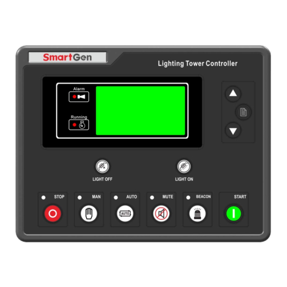
ALC700 Series Light Tower Set Controller 5 OPERATION 5.1 PUSHBUTTONS Icon Description Stop running light tower set; Stop/Reset Reset alarm when failure occurs; Lamp test in stop mode (press at least 3 seconds); Manual Mode Press this key and controller enters in Manual mode. -
Page 11: Lcd Display
ALC700 Series Light Tower Set Controller 5.2 LCD DISPLAY Display Description First screen display all lights status, average voltage , generator frequency, generator running status and alarm information. U = 220V F = 50.0Hz Light On: GENERATOR NORMAL RUNNING Light Off:... - Page 12 ALC700 Series Light Tower Set Controller Display Description GENERATOR Press button STARTS 88888 times The screen display accumulated start times, HOURS RUN 009999:05:30 accumulated energy, accumulated run time ENERGY 0003561.6 kWh (HH: MM: SS). LOAD Press button CURRENT 500 500 500 A...
-
Page 13: Scheduled Start/Stop
ALC700 Series Light Tower Set Controller 5.3 SCHEDULED START/STOP ,its indicator light on, and controller enters Auto mode. Meanwhile, the panel A. Press display Auto Mode Select (Fig 1); Press to select 01 Auto Timer Mode and press to confirm (Fig 2); Press... - Page 14 ALC700 Series Light Tower Set Controller Fig 6 STOP DELAY 09:06:02 START TIME 16:28:00 CURRENT TIME 16:33:58 GENERATOR NORMAL RUNNING D. When “stop delay” time is 00:00:00 or repeat above-mentioned A procedure, select 02 TIMER STOP (01 TIMER START must be reselect if another time scheduled start is needed),...
-
Page 15: Sunrise/Sunset Mode
ALC700 Series Light Tower Set Controller 5.4 SUNRISE/SUNSET MODE If the city information haven’t been set when select this mode, users should connect PC and ALC700 controller using USB or RS485 communication line and set the city information first. The procedures as following: Open test software—edit configuration—set sunrise/sunset—select city/user-defined city... - Page 16 ALC700 Series Light Tower Set Controller C. If generator voltage and frequency has reached on-load requirements (Voltage ≥ on-load voltage and frequency ≥ on-load frequency), all the lights will illuminate in proper order and the illumination interval delay is 2s (can be set as 1~300s). (Fig 5,6)
-
Page 17: Auto Sms Mode
ALC700 Series Light Tower Set Controller 5.5 AUTO SMS MODE ,its indicator light on, and controller enters Auto mode. Meanwhile, the panel A. Press display Auto Mode Select (Fig 1); Press to select 02 Auto SMS Mode and press to confirm (Fig 2). - Page 18 ALC700 Series Light Tower Set Controller D. When SMS message module receives the stop command, the 1#~8# lights will off in proper order and the extinguishing interval delay can be set as 1s~300s. The light tower set begin stopping when all the lights off. (Fig 6,7)
-
Page 19: Auto Sms Sunrise/Sunset Mode
ALC700 Series Light Tower Set Controller 5.6 AUTO SMS SUNRISE/SUNSET MODE ,its indicator light on, and controller enters Auto mode. Meanwhile, the panel A. Press display Auto Mode Select (Fig 1); Press to select 02 Auto SMS Mode and press to confirm (Fig 2). - Page 20 ALC700 Series Light Tower Set Controller D. If generator voltage and frequency has reached on-load requirements (Voltage ≥ on-load voltage and frequency ≥ on-load frequency), all the lights will illuminate in proper order and the illumination interval delay is 2s (can be set as 1~300s). (Fig 5,6)
-
Page 21: Remote Start Mode
ALC700 Series Light Tower Set Controller 5.7 REMOTE START MODE A. Set arbitrary input port as “Remote Start”. Press ,its indicator light on, and controller enters Auto Mode. Meanwhile, the panel display Auto Mode Select (Fig 1); Press to select 04 REMOTE START and press to confirm (Fig 2). - Page 22 ALC700 Series Light Tower Set Controller D. When remote start input port is inactive, remote stop delay begins (same as start delay); when stop delay is over, 1#~8# lights will off in proper order and the extinguishing interval delay can be set as 1s~300s. The light tower set begin stopping when all the lights off.
-
Page 23: Manual Start/Stop
ALC700 Series Light Tower Set Controller 5.8 MANUAL START/STOP ,its indicator light on, and controller enters Manual Mode (Picture 1). Press A. Press ,light tower set begin cranking (Fig 2). Fig 1 MANUAL MODE WAIT MANUAL START CURRENT TIME 12:05:18... - Page 24 ALC700 Series Light Tower Set Controller D. Press , 1#~8# lights will off in proper order and the extinguishing interval delay can be set as 1s~300s. The light tower set begin stopping when all the lights off. Press again during this procedure will lead to all lights off at the same time and ETS status of...
-
Page 25: Protections
ALC700 Series Light Tower Set Controller 6 PROTECTIONS 6.1 WARNING ALARMS Warnings are not shutdown alarms and do not affect the operation of the genset. Alarm information will be displayed on the LCD. Warning alarms types are as follows: Type... - Page 26 ALC700 Series Light Tower Set Controller Type Description If generator output electricity after the “ETS solenoid delay/ fail to stop delay” is over, it will send warning signal and the Fail to Stop corresponding alarm information will be displayed on the LCD.
-
Page 27: Shutdown Alarms
ALC700 Series Light Tower Set Controller 6.2 SHUTDOWN ALARMS When controller detects shutdown alarm, it will send signal to turn off #1~#8 lights and shuts down generator. Shutdown alarms as following: Type Description When controller detects emergency stop signal, it will send a... - Page 28 ALC700 Series Light Tower Set Controller Type Description When controller detects the oil pressure sensor is open circuit, Pressure Sensor it will send shutdown signal and the corresponding alarm Open information will be displayed on the LCD. When controller detects the temperature sensor is open circuit, Temp.
-
Page 29: Trip And Stop Alarms
ALC700 Series Light Tower Set Controller 6.3 TRIP AND STOP ALARMS When the controller detects trip and stop signal, it will send signal to turn off #1~#8 lights and then generator is cooling down and stopped. Shutdown alarms as following:... -
Page 30: Wiring Connection
ALC700 Series Light Tower Set Controller 7 WIRING CONNECTION ALC700 controller’s rear as following: Description of terminal connection: Functions Cable Size Remark Connected with negative starter DC input B- 2.5 mm battery. Connected with positive of starter battery. DC input B+ 2.5 mm... - Page 31 ALC700 Series Light Tower Set Controller Functions Cable Size Remark 4# Light Output 1.5 mm 5#-8# COM 2.5 mm 5# Light Output 1.5 mm Total output current: 8A If 1~4 is all used, the maximum current of 6# Light Output 1.5 mm...
- Page 32 ALC700 Series Light Tower Set Controller Functions Cable Size Remark B- is active. 4# light control feedback input; connect 4# Light Input 1.0 mm B- is active. 5# light control feedback input; connect 5# Light Input 1.0 mm B- is active.
-
Page 33: Scopes And Definitions Of Programmable Parameters
ALC700 Series Light Tower Set Controller 8 SCOPES AND DEFINITIONS OF PROGRAMMABLE PARAMETERS 8.1 CONTENTS AND SCOPES OF PARAMETERS Form 1 Parameters DET Range Default Remarks 0 Daily 1 Weekly 01 TIMER MODE SELECT 2 Monthly 3 Custom Week Daily... - Page 34 ALC700 Series Light Tower Set Controller Other parameters configuration (only configured by software via PC) Parameters Default Start Delay Pre-heat Delay Cranking Time Crank Rest Time Safety On Delay Start Idle Time Warming Up Time Cooling Time Stop Idle Time...
- Page 35 ALC700 Series Light Tower Set Controller Parameters Default Output Port 2 Common alarm; Normally open output Output Port 3 Flashlight output; Normally open output Output Port 4 Audible alarm output; Normally open output Input Port 1 Custom Delay Input Port 2 Custom Delay...
-
Page 36: Enable Definition Of Programmable Output Port 1-4
ALC700 Series Light Tower Set Controller 8.2 ENABLE DEFINITION OF PROGRAMMABLE OUTPUT PORT 1-4 Type Description Not Used Action when over speed shutdown and emergence Air Flap stop. It also can close the air inflow to stop the engine as soon as possible. - Page 37 ALC700 Series Light Tower Set Controller Type Description Reserved Reserved Emergency Stop Action when emergency stop alarm. ETS Control Action during ETS delay. Failed To Start Action when failed start alarm. It is controlled by fuel pump of level sensor’s limited Fuel Pump Control threshold.
- Page 38 ALC700 Series Light Tower Set Controller Type Description Over Speed Shutdown Action when over speed shutdown alarm. Preheat (during preheat Action in period of preheat delay to cranking. timer) Action in period of preheat delay to the end of cranking Preheat (until end of crank) delay.
-
Page 39: Enable Definition Of Programmable Input Port 1-4
ALC700 Series Light Tower Set Controller 8.3 ENABLE DEFINITION OF PROGRAMMABLE INPUT PORT 1-4 Type Description Including following functions, Indication: indicate only, not warning or shutdown. Warning: warn only, not shutdown. Shutdown: alarm and shutdown immediately Users Configured Trip and stop: alarm, generator unloads and shutdown after... -
Page 40: Sensor Selection
ALC700 Series Light Tower Set Controller 8.5 SENSOR SELECTION Items Contents Remark 0 Not used 1 Digital closed 2Digital open The range of user-defined 3 VDO 120 degrees C resistor type sensor is 4 Datcon high 0-999 Ohm; by default... -
Page 41: Sensors Setting
ALC700 Series Light Tower Set Controller 8.6 SENSORS SETTING 1. When reselect sensors, the sensor curve will be transferred into the standard value. For example, if temperature sensor is SGX (120°C resistor type), its sensor curve is SGX (120°C resistor type); if select the SGD (120°C resistor type), the temperature sensor curve is SGD curve. -
Page 42: Over Current Action
ALC700 Series Light Tower Set Controller 8.7 OVER CURRENT ACTION The formula of over current delay value: T = t / ((IA/IT)-1) T:Overcurrent delay (second) t:Timing multiplier ratio IA:Current max. load current(L1/L2/L3) IT:Overcurrent setting value Example: t = 36 IA = 600A... -
Page 43: Light Inputs Settings
ALC700 Series Light Tower Set Controller 8.9 LIGHT INPUTS SETTINGS Work mode can be set as:Feedback input, Control input, Invalid. The control logic is as following: Light Inputs TFT Light Light Relay Panel Light System Mode Setting Status Output Status... -
Page 44: Sms (Order And Reply)
ALC700 Series Light Tower Set Controller 8.12 SMS (ORDER AND REPLY) SMS Code Description Stop mode order; set controller into stop mode; Stop SMS STOP running light tower set; Reply:SMS STOP OK Start order; can control light tower set to start;... -
Page 45: Parameters Setting
ALC700 Series Light Tower Set Controller 9 PARAMETERS SETTING 1) Parameters Setting:After controller power on, press , then select 1 Set Parameters, then press again to advanced parameter password confirmation interface. Press to increase or decrease values and input the corresponding password 0~9;... -
Page 46: Event Log
ALC700 Series Light Tower Set Controller EVENT LOG Maximum 99 pieces of event logs can be circularly stored into controller. Shutdown alarms and real time information will be record but warning alarms. If the alarm records are more than 99 pieces, then the latest record will replace the oldest one. -
Page 47: Commissioning
ALC700 Series Light Tower Set Controller COMMISSIONING Please make the under procedures checking before commissioning, 1. Ensure all the connections are correct and wires diameter is suitable. 2. Ensure that the controller DC power has fuse, controller’s positive and negative connected to start battery are correct. -
Page 48: Typical Wiring Diagrams
ALC700 Series Light Tower Set Controller TYPICAL WIRING DIAGRAMS ALC708 Typical Wiring Diagram Note: If 8 lights are all used, the maximum current of each light is 2A. ALC704 Typical Wiring Diagram Note: If 4 lights are all used, the maximum current of each light is 2A. -
Page 49: Installation
ALC700 Series Light Tower Set Controller DC Generator Typical Wiring Diagram NOTE: Users should select suitable Hall DC sensor according to the output power and current of the light tower set. INSTALLATION Controller is panel built-in design; it is fixed by clips when installed. The controller’s overall dimensions and cutout dimensions for panel, please refers to as following, 13.1 BATTERY VOLTAGE INPUT... -
Page 50: Output And Expand Relays
ALC700 Series Light Tower Set Controller connected to No.34 and No.35 terminals in controller. The output voltage of speed sensor should be within AC(1~24)V (effective value) during the full speed. AC12V is recommended (in rated speed). When install the speed sensor, let the sensor is spun to contacting flywheel first, then, port out 1/3 lap, and lock the nuts of sensor at last. -
Page 51: Fault Finding
ALC700 Series Light Tower Set Controller FAULT FINDING Here are the common faults and troubleshooting. If there is any other problem, please feel free to contact SmartGen’s service. Symptoms Possible Solutions Check starting batteries; Controller no response with Check controller connection wirings;...
Need help?
Do you have a question about the ALC700 SERIES and is the answer not in the manual?
Questions and answers
Can the HOURS RUN from old control unit be put into new control unit