Table of Contents
Advertisement
Quick Links
Advertisement
Table of Contents

Related Manuals for Maxcess MAGPOWR TLC-B Load Cell


Summary of Contents for Maxcess MAGPOWR TLC-B Load Cell
- Page 1 MAGPOWR TENSION CONTROL MAGPOWR TLC-B Load Cell User Manual MI 850A356 1 A...
-
Page 2: Table Of Contents
CONTENT INTRODUCTION About these operating instructions ..............1-1 Product overview ....................1-2 SAFETY INSTRUCTIONS Instructions for use ....................2-1 Symbols used ....................... 2-2 Proper use ......................2-3 Installation and commissioning ................2-3 Maintenance and repair ..................2-3 Decommissioning....................2-3 MOUNTING DIMENSIONS Product dimensions.................... -
Page 3: Introduction
INTRODUCTION About these All of the information herein is the exclusive proprietary property of Maxcess International, and is disclosed with the operating understanding that it will be retained in confidence and will instructions neither be duplicated nor copied in whole or in part nor be used for any purpose other than for which disclosed. -
Page 4: Product Overview
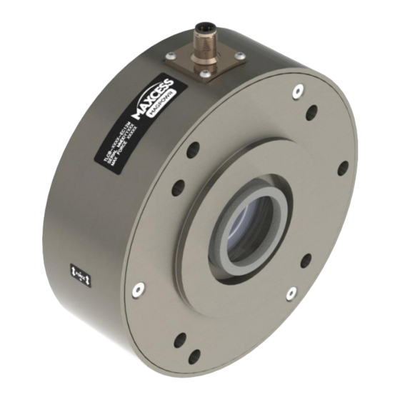
INTRODUCTION Product overview The MAGPOWR TLC-B Load Cells are extremely accurate devices used to measure tension in any unwind, rewind, or intermediate web processing application. The load cells are to be mounted in a machine supporting an idler roll in a part of the machine where measurement of web tension is desired. -
Page 5: Safety Instructions
SAFETY INSTRUCTIONS Instructions for To ensure safe and problem free installation of the load cell device, the load cell must be properly transported and stored, professionally installed and placed in operation. Proper operation and maintenance will ensure a long service life of the device. -
Page 6: Symbols Used
SAFETY INSTRUCTIONS Symbols used The following safety identification symbols are used in these operating instructions. WARNING/CAUTION – General danger or important note Reference to general hazards that may result in bodily injuries or damage to device or material. WARNING/CAUTION – Danger due to crushing Reference to danger of injury caused by crushing. -
Page 7: Proper Use
SAFETY INSTRUCTIONS Basic safety information Proper use The load cell devices are intended to be used on machines or systems to monitor the tension in a web. Indoor operation. Improper use Operation outside the technical specifications Operation in an Ex-area or intrinsically safe area, unless used with a MAGPOWR IS2 barrier. -
Page 8: Mounting Dimensions
MOUNTING DIMENSIONS Product dimensions TLC-B Note: Cable connector adds 20 mm [0.80 inches] to overall height; see page 4-4. Customer supplied Shaft length requirements (in millimeters; for reference only) Mount outside machine frames Mount inside machine frames www.maxcessintl.com MAGPOWR TLC-B MI 850A356 1 A... -
Page 9: Shaft And Roller Diameters
MOUNTING DIMENSIONS Shaft and roller diameters When mounting inside the machine frame, clearance is required for the installation fasteners. See dimensions illustrated below. If 'Y' will be less than 50 mm [2.0 inches], then the roller diameter 'X' should be less than the diameter of the intended mounting bolt circle: 3-bolt pattern: 150 mm [3.5 inches] maximum 4-bolt pattern: 135 mm [3.0 inches] maximum... -
Page 10: Installation
INSTALLATION Load cell mounting options Flange mount (on vertical machine frame) Inside frame Outside frame Pillow block mount (on horizontal machine frame; configurations vary) Inside brackets Outside brackets www.maxcessintl.com MAGPOWR TLC-B MI 850A356 1 A... -
Page 11: General Installation
INSTALLATION General installation CAUTION – Possible damage to load cell. Do not hammer on the load cell. CAUTION – Possible damage to load cell. Do not disassemble the load cell – there are no serviceable parts inside the unit. WARNING – Danger of injury from crushing. Maintenance and repair tasks on the load cell device must be performed only when the machine has been stopped and has been secured from being turned on again. -
Page 12: Resultant Force Polarity
INSTALLATION Resultant force polarity The label on the load cell indicates the output polarity based on the resultant force direction in relation to the connector. Default wiring Cable wiring diagram + Power Pin 1 (A) + Signal Pin 2 (B) White - Signal Pin 3 (C) -
Page 13: Flange Mounting
INSTALLATION Flange mounting The TLC-B Load Cell can be mounted using one of two bolt patterns: 3-hole on a 150 mm bolt circle 4-hole on a 135 mm bolt circle Before installation, each machine frame must be prepared with a 100 mm hole for the load cell hub and M8x1 (or 5/16") threaded holes for the fasteners. -
Page 14: Pillow Block Mounting
INSTALLATION Pillow block mounting When using the optional pillow block bracket, the load cell can be rotated in 30° increments to align the resultant force with the connector. One bracket per load cell required; - MAGPOWR Part No. TLCB-PBK Fasteners Mount load cell to pillow block bracket (kit included) - M8 bolts - Minimum fastener length is 75 mm [3.0 inches]... -
Page 15: Bearing And Shaft Installation
Retaining ring, internal, outboard Connector Cover, outboard 40 mm if not using dust seal Customer supplied or purchase from Maxcess Note: Items 5 and 11 are the same part number, and are distinguished here by description. www.maxcessintl.com MAGPOWR TLC-B MI 850A356 1 A... -
Page 16: Inside Machine Frame
INSTALLATION Bearing and shaft installation – continued Inside machine frame Use the illustration on page 4-6 for reference. Note the overload pins that are loose inside the covers. Ensure that they are in place before reinstalling the covers. NOTE: A fixed load cell uses two large retaining rings to secure the bearing;... - Page 17 INSTALLATION Bearing and shaft installation Inside machine frame mounting – continued 5. Install the bearing on the shaft and secure with the snap ring. 6. Slide the load cell assembly back over the bearing. 7. Push the dust seal into the pocket of the cover until inboard faces are flush.
- Page 18 INSTALLATION Bearing and shaft installation Inside machine frame mounting – continued Installing the shaft assembly 1. Align the shaft assembly between the machine frames and slide the floating load cell inboard until the hubs fit between the frames. There will be some axial clearance to allow for fit.
-
Page 19: Outside Machine Frame
4-10 INSTALLATION Bearing and shaft installation – continued Outside machine frame Use the illustration on page 4-6 for reference. Note the overload pins that are loose inside the covers. Ensure that they are in place before reinstalling the covers. NOTE: A fixed load cell uses two large retaining rings to secure the bearing; a floating load cell uses none. - Page 20 4-11 INSTALLATION Bearing and shaft installation Outside machine frame mounting – continued 7. Ensure the overload pins are in place and reinstall the outboard cover. 8. Fasten the load cell to the machine frame using customer provided fasteners. Minimum fastener length is 70 mm [2.75 inches].
-
Page 21: Maintenance
MAINTENANCE Maintenance No maintenance is required for the model TLC-B load cells other than periodic lubrication of the bearings on the live shaft applications. For MAGPOWR supplied bearings (Part No. 30A23-7), application of fluorosilicone grease at least once annually is recommended. www.maxcessintl.com MAGPOWR TLC-B MI 850A356 1 A... -
Page 22: Model Number Key
MODEL NUMBER KEY Model number key TLC – B – 500 - EC12M Load rating Connnector Units Model Size type (Metric) (Newtons) Available models Load Rating Model number TLC-B-500-EC12M TLC-B-1000-EC12M 1000 TLC-B-2000-EC12M 2000 TLC-B-3000-EC12M 3000 www.maxcessintl.com MAGPOWR TLC-B MI 850A356 1 A... -
Page 23: Product Specifications
SPECIFICATIONS Product specifications Warning – Do not use the devices outside of their rated specifications Gage resistance 350 ohm Gage type Metal foil, full Wheatstone bridge Excitation voltage 10 VDC maximum 1.5 mV/V, 15 mVDC maximum at full Output signal load rating with 10 VDC excitation IP67 with dust seal IP rating... - Page 24 AND AFRICA AND SE ASIA Tel +1.405.755.1600 Tel +86.756.881.9398 Tel +91.22.27602633 Tel +81.43.421.1622 Tel +49.6195.7002.0 asia@maxcessintl.com Fax +1.405.755.8425 Fax +86.756.881.9393 Fax +91.22.27602634 Fax +81.43.421.2895 Fax +49.6195.7002.933 www.maxcess.asia sales@maxcessintl.com info@maxcessintl.com.cn india@maxcessintl.com japan@maxcessintl.com sales@maxcess.eu www.maxcessintl.com www.maxcessintl.com.cn www.maxcess.in www.maxcess.jp www.maxcess.eu © 2017 Maxcess...
Need help?
Do you have a question about the MAGPOWR TLC-B Load Cell and is the answer not in the manual?
Questions and answers