
Related Manuals for Maxcess FIFE-500-XL


Summary of Contents for Maxcess FIFE-500-XL
- Page 1 FIFE GUIDING SOLUTIONS FIFE-500-XL Installation and Service Manual Medium Web Guiding System MI 1-917 1 C...
-
Page 3: Table Of Contents
Operator interface screen ................4-2 MODEL NUMBER KEY ................5-1 SPECIFICATIONS ..................6-1 General ........................6-1 Certifications and environmental compatibility ............6-1 Inputs and outputs ....................6-2 Maximum cable lengths ................... 6-2 SERVICE AND REPLACEMENT PARTS ............7-1 www.maxcessintl.com FIFE-500-XL MI 1-917 1 C... -
Page 4: Introduction
All of the information herein is the exclusive proprietary property of Maxcess International, and is disclosed with the understanding that it will be retained in confidence and will neither be duplicated nor copied in whole or in part nor be used for any purpose other than for which disclosed. -
Page 5: Product Overview
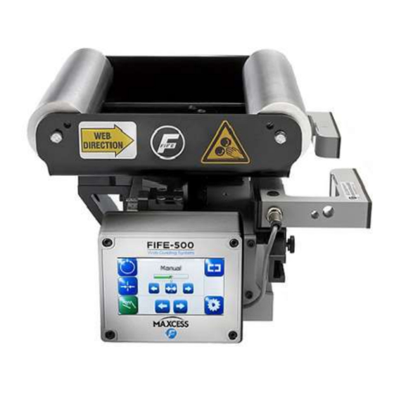
1–2 INTRODUCTION Product overview The FIFE-500-XL web guiding system is a complete offset pivot guide and controller in a compact package with an IP54 environmental rating. The FIFE-500-XL is available in many standard roll face, guide span and roller diameters. -
Page 6: Safety Instructions
The signal word WARNING refers to the danger of moderate to severe bodily injuries. The signal word CAUTION refers to the danger of slight to moderate bodily injuries or material damage. The signal word NOTICE refers to the possibility of damage to equipment. www.maxcessintl.com FIFE-500-XL MI 1-917 1 C... -
Page 7: Symbols Used
WARNING/CAUTION – Danger due to voltage, electric shock Reference to danger of injury caused by electric shock due to voltage. WARNING/CAUTION – Danger due to hot surfaces Reference to risk of injury caused by burning. www.maxcessintl.com FIFE-500-XL MI 1-917 1 C... -
Page 8: Basic Safety Information
WARNING – The web guiding system contains rotating and moving parts which could cause injury due to crushing. Appropriate protective guards must be installed by the user according to his use of this product. www.maxcessintl.com FIFE-500-XL MI 1-917 1 C... - Page 9 Appropriate equipment is to be used and the safety rules of the company must be observed. Decommissioning The web guiding system must be disposed of in accordance with all the applicable national, state and local regulations. www.maxcessintl.com FIFE-500-XL MI 1-917 1 C...
-
Page 10: Installation
WARNING – Death or injury can result from unexpected movement. Protect against unexpected movement by removing electrical power from the FIFE-500-XL and the machine into which the FIFE- 500-XL is installed. WARNING – Danger of injury from crushing. Maintenance and repair tasks on the FIFE-500-XL must be performed only when the machine has been stopped and has been secured from being turned on again. - Page 11 272.5 [10.728] 47.5 [1.870] T-nut block, 6X T-nut channel, 2X Clamping screw, 6X M8x1.25, 15 [0.59] maximum depth, 6X mounting 234.5 [9.232], mounting ‘W’-64 [2.520] maximum, mounting Figure 1. FIFE-500-XL with integrated sensor mounting www.maxcessintl.com FIFE-500-XL MI 1-917 1 C...
-
Page 12: Mounting Dimensions
2) The weight is a maximum with 100 mm rollers and the splice table. The 80 mm rollers reduce the weight by 2% and the removal of the splice table reduces the weight by about 10%. www.maxcessintl.com FIFE-500-XL MI 1-917 1 C... -
Page 13: Guiding Parameters
21.22 [0.84] 500 [19.69] 150 [5.91] 25.16 [0.99] [31.50] 600 [23.62] 137 [5.39] 26.41 [1.04] 400 [15.75] 140 [5.51] 21.22 [0.84] 500 [19.69] 150 [5.91] 25.16 [0.99] [35.43] 600 [23.62] 137 [5.39] 26.41 [1.04] www.maxcessintl.com FIFE-500-XL MI 1-917 1 C... -
Page 14: Pneumatic Connection To Splice Table
6 mm OD pneumatic tube fitting, 2X Adjustable splice table Locking knob 50.8 [2.000], tape width maximum 1.5 [0.059] maximum web thickness Ø76.2 [Ø3.000] tape core Customer provided tape Figure 2. Splice table with tape dispenser www.maxcessintl.com FIFE-500-XL MI 1-917 1 C... -
Page 15: Installing The Operator Interface
Base Assembly. If it is desired to relocate the OI from one end of the Base Assembly to the other, use the following procedure. 1. Disconnect power from the FIFE-500-XL unit. 2. Using a 3 mm Allen wrench, remove the four screws that retain the OI to the Base Assembly end plate. -
Page 16: Panel Mount Model
Units are in millimeters [inches]. 124 [4.882] R4 [0.157] MAX (4X) Operator interface Panel Mounting bracket Panel jack screws Installation cut-out Figure 3. Operator interface panel mount kit installation www.maxcessintl.com FIFE-500-XL MI 1-917 1 C... -
Page 17: Wall Mount Model
Units are in millimeters [inches]. 111 [4.370] M4 x 0.7 (4X) 87.7 [3.453] Operator interface Operator interface shroud Wall igure 4. Operator interface wall mount kit installation www.maxcessintl.com FIFE-500-XL MI 1-917 1 C... -
Page 18: Electrical Installation
See Figure 5. 6. Place the power connector on the mating connector on the web guiding system and secure with the mounting screw. Be sure the gasket is installed at the mating interface of the connectors. www.maxcessintl.com FIFE-500-XL MI 1-917 1 C... -
Page 19: Digital Inputs And Outputs
24 V GND +24 V Section A-A (rear view) 18 AWG wire recommended Gasket Figure 5. FIFE-500-XL power connection Digital inputs and Digital inputs and outputs are available for remote control and signalling functions. There are 6 digital inputs allowing control outputs of the following modes External Lock, Automatic, Manual, Servo- Center, Jog, RGPC, and sensor selection. - Page 20 WARNING – Death or injury can result from unexpected movement. If the timing requirements of the digital inputs are not met, unexpected motion of the guide could result when a sensor selection is misinterpreted as a mode change to Servo Center or Auto. www.maxcessintl.com FIFE-500-XL MI 1-917 1 C...
- Page 21 INSTALLATION Table 2. Digital output matrix default configuration 1 = ACTIVE - = IGNORE OUTPUTS* STATUS LOSS OF NULL (AUTOMATIC MODE) CENTERED (SERVO-CENTER MODE) MOTOR BLOCKED POWER OK * Digitial outputs are active low www.maxcessintl.com FIFE-500-XL MI 1-917 1 C...
-
Page 22: Wiring Diagrams
PAR_13 PAR_I4 PAR_I5 LINESPEED MOTOR_A BLACK X102 MOTOR_B RGPC_LED WHITE BROWN MOTOR_C RS485+ BLACK RS485- BLUE +24V X101 WHITE BLACK POWER OI_+24V INPUT N.C. FEMALE TO OPERATOR INTERFACE Figure 7. FIFE-500-XL basic wiring diagram www.maxcessintl.com FIFE-500-XL MI 1-917 1 C... - Page 23 LINESPEED BLACK MOTOR_A BROWN MOTOR_B X102 RGPC_LED MOTOR_C RS485+ RS485- +24V X101 OI_+24V PARALLEL I/O CABLE N.C. 217497-XXX Figure 8. FIFE-500-XL parallel I/O connections RGPC-50/F WIRING ENC_A +12V ENC_B SENSOR_B SENSOR_A +12V HALL_A X103 HALL_B HALL_C ISCT -12V PAR_O3 PAR_O2...
- Page 24 PAR_I0 PAR_I1 PAR_I2 X104 PAR_13 PAR_I4 PAR_I5 LINESPEED MOTOR_A MOTOR_B X102 RGPC_LED MOTOR_C RS485+ RS485- +24V X101 OI_+24V N.C. Figure 11. FIFE-500-XL sensor connections for sensors SE-11, SE-17, SE-22, SE-23, SE-31-IP, SE-38, SE-42R, SE-44R www.maxcessintl.com FIFE-500-XL MI 1-917 1 C...
- Page 25 +12V CONTROLLER PCB ASSY +12V PAR_I0 PAR_I1 PAR_I2 X104 PAR_13 PAR_I4 PAR_I5 LINESPEED MOTOR_A X102 MOTOR_B RGPC_LED MOTOR_C RS485+ RS485- +24V X101 OI_+24V N.C. Figure 12. FIFE-500-XL sensor connections for sensors SE-26A, SE-46A-C, DSE-17 www.maxcessintl.com FIFE-500-XL MI 1-917 1 C...
-
Page 26: Maintenance
Maintenance WARNING – Death or injury can result from unexpected movement. Protect against unexpected movement by removing electrical power from the FIFE-500-XL and the machine into which the FIFE-500-XL is installed. WARNING – Danger of injury from crushing. Maintenance and repair tasks on the FIFE-500-XL must be performed only when the machine has been stopped and has been secured from being turned on again. -
Page 27: Sensors
Do not directly spray the screen. Compressed air or a shop vacuum may also be used as necessary. www.maxcessintl.com FIFE-500-XL MI 1-917 1 C... -
Page 28: Model Number Key
500 [19.69] 80 [3.150] 100 [3.937] 600 [23.62] 400 [15.75] NONE 800 [31.50] 500 [19.69] 80 [3.150] 100 [3.937] 600 [23.62] 400 [15.75] NONE 900 [35.43] 500 [19.69] 80 [3.150] 100 [3.937] 600 [23.62] www.maxcessintl.com FIFE-500-XL MI 1-917 1 C... - Page 29 [13.78], a guide span of 500 [19.69], a roller diameter of 80 [3.150], a quantity of two SE-23 without Air Sweep sensors, a fine adjustment sensor bracket, a splice table with tape dispenser and rollers with rubber cork tape. www.maxcessintl.com FIFE-500-XL MI 1-917 1 C...
-
Page 30: Specifications
Certifications and environmental compatibility Product certifications – TUV Rheinland of North America to UL61010-1 CAN/CSA-C22.2 No. 61010-1 and CB Certificate to IEC61010-1 Protection class – IP 54 (applies only when all connectors are mated) www.maxcessintl.com FIFE-500-XL MI 1-917 1 C... -
Page 31: Inputs And Outputs
Power cable (18 AWG) – 15 m (50 ft) suggested. (Longer cables may be used if the voltage at the FIFE-500-XL is verified to be within the required 18-30 VDC input range). The suggested maximum length is 20 m (65 ft). - Page 32 When ordering replacement parts, please indicate, where possible, part number, drawing number and model description. If it is necessary to return the FIFE-500-XL for service, care must be taken to properly package the unit to prevent damage during shipment. If possible, use the original shpping containers.
Need help?
Do you have a question about the FIFE-500-XL and is the answer not in the manual?
Questions and answers