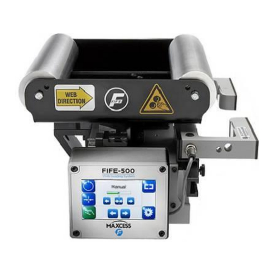
Maxcess FIFE-500 Quick Start Manual
Narrow web guiding system
Hide thumbs
Also See for FIFE-500:
- Installation and service manual (32 pages) ,
- Quick start setup (16 pages) ,
- User manual (80 pages)

Related Manuals for Maxcess FIFE-500


Summary of Contents for Maxcess FIFE-500
- Page 1 FIFE GUIDING SOLUTIONS FIFE-500 Quick-Start Manual Narrow Web Guiding System MI 2-263 1 B...
-
Page 3: Table Of Contents
Display definitions ....................2-1 Button functions and definitions ................2-3 Status bar definitions ..................... 2-4 OPERATION ....................3-1 System setup ......................3-1 Auto setup configuration ..................3-3 Optional manual configuration ................3-5 Changing the guidepoint ..................3-6 www.maxcessintl.com FIFE-500 MI 2-263 1 B... -
Page 4: Introduction
Copyright information All of the information herein is the exclusive proprietary property of Maxcess International, and is disclosed with the understanding that it will be retained in confidence and will neither be duplicated nor copied in whole or in part nor be used for any purpose other than for which disclosed. -
Page 5: Features
FEATURES Display definitions The FIFE-500 uses a QVGA Touchscreen for Operator command inputs and status displays. This Control Panel is divided into 5 sections of information for which a brief description is listed below. Refer to the Figure 1, for the button locations in the standard, horizontal Control Panel. Also... - Page 6 5. The horizontal section along the bottom contains the Sensor Selection and Setup buttons and indicates the current Sensor Mode selection by displaying the proper sensor symbol in the Sensor Select button. Figure 2. FIFE-500 CONTROL PANEL (90° AND 270° ROTATION) www.maxcessintl.com FIFE-500...
-
Page 7: Button Functions And Definitions
FEATURES Button functions and definitions The table below gives the name along with an operational function description of each button displayed on the FIFE-500 Web Guiding System. AUTOMATIC This button initiates the Automatic mode. Correction is applied to the web by moving the guide in response to the output of the sensor(s) that have been selected. -
Page 8: Status Bar Definitions
Status bar definitions The status bar located horizontally across the top of the FIFE-500 Web Guide Operator Level screen remains visible at all times. The number on the left side of the status bar contains the numerical address of the connected motor controller. The number on the right side of the status bar indicates a hierarchical screen number. - Page 9 FEATURES MENU TIMEOUT The menu screens in the FIFE-500 Web Guiding System close automatically after 3 minutes of touch screen inactivity. The inactivity timeout option and the timeout value are configurable. The clock icons will appear during stages of the timeout process as the inactivity timer counts down.
- Page 10 System User Manual, Figure Sheet 2-262. ASC ACTIVE Automatic Sensor Control (ASC) is enabled and the ASC state has been triggered. Automatic guide movement is prohibited. FIFE-500 Web Guiding System See the menu description for ASC in the User Manual, MI 2-262.
-
Page 11: Operation
OPERATION System setup Setup screens Figure 3. FIFE-500 CONTROL PANEL LEVEL 1 SETUP SCREEN Figure 4. FIFE-500 CONTROL PANEL SENSOR CALIBRATION SCREEN 1. Connect +24 VDC Power to the input receptacle, located on the top side of the MI 1-915 Base Assembly. - Page 12 Press the BACK or HOME button to return to the Operator Level screen. In simulation, these buttons are not available. Once this procedure has been performed for each sensor, it does not need to be repeated, unless the web/strip opacity has changed. www.maxcessintl.com FIFE-500 MI 2-263 1 B...
-
Page 13: Auto Setup Configuration
Auto setup configuration NOTE: If Manual Configuration is desired, go to page 3-5. Figure 5. FIFE-500 CONTROL PANEL AUTOSETUP SCREEN 1. Place the web/strip in the proper position and then position the sensor(s) to align the center of the sensor(s) bandwidth with the edge of the web/strip to be guided. - Page 14 Press the Autosetup button to start. The guide will move a short distance and indicate the result as shown in Figure 6 below. Figure 6. FIFE-500 CONTROL PANEL SUCCESSFUL AUTOSETUP COMPLETION 4. Press the ACCEPT button to save the setting.
-
Page 15: Optional Manual Configuration
OPERATION Optional manual configuration Figure 7. FIFE-500 CONTROL PANEL SYSTEM GAIN SETUP SCREEN Setting the gain 1. Press the SETUP button to enter the Setup menus. 2. Press the GAIN icon to enter the Gain menu. 3. Use the + and - ARROW buttons, or use the slider control to adjust the Gain to the desired level. -
Page 16: Changing The Guidepoint
OPERATION Optional manual configuration Figure 8. FIFE-500 CONTROL PANEL GUIDEPOINT SETUP SCREENS Changing the guidepoint while in automatic or manual mode The arrow controls shift the Guidepoint within the active sensor bandwidth. Press the center button near the bar graph to reset the Guidepoint to the default of 50%.
Need help?
Do you have a question about the FIFE-500 and is the answer not in the manual?
Questions and answers