Sign In
Upload
Download
Table of Contents
Contents
Add to my manuals
Delete from my manuals
Share
URL of this page:
HTML Link:
Bookmark this page
Add
Manual will be automatically added to "My Manuals"
Print this page
×
Bookmark added
×
Added to my manuals
Manuals
Brands
Planmeca Manuals
Medical Equipment
Proline EC pan
Technical manual
Planmeca Proline EC pan Technical Manual
Hide thumbs
1
2
Table Of Contents
3
4
5
6
7
8
9
10
11
12
13
14
15
16
17
18
19
20
21
22
23
24
25
26
27
28
29
30
31
32
33
34
35
36
37
38
39
40
41
42
43
44
45
46
47
48
49
50
51
52
53
54
55
56
57
58
59
60
61
62
63
64
65
66
67
68
69
70
71
72
73
74
75
76
77
78
79
80
81
82
83
84
85
86
87
88
89
90
91
92
93
94
95
96
97
98
99
100
101
102
103
104
105
106
107
108
109
110
111
112
113
114
115
116
117
118
119
120
121
122
123
124
125
126
127
128
129
130
131
132
133
134
135
136
137
138
139
140
141
142
143
144
145
146
147
148
149
150
151
152
153
154
155
156
157
158
159
160
161
162
163
164
165
166
167
168
169
170
171
172
173
174
175
176
177
178
179
180
181
182
183
184
185
186
187
188
189
190
191
192
193
194
195
196
197
198
199
200
201
202
203
204
205
206
207
208
209
210
page
of
210
Go
/
210
Contents
Table of Contents
Bookmarks
Table of Contents
Table of Contents
General & Technical Data
Warnings
Manual Versions
Technical Specifications
User's Statement for Planmeca Proline Ec
Panoramic X-Ray
Emc Information
Keyboard Functions & Modes
Keyboard Overview
Normal Mode Keyboard Functions
Normal User Functions
Special User Settings
Automatic Return
Temple Rest Motor Inactivation
Automatic Temple Rest Closing Inactivation
Test Mode
Parameter History Display
Autoprint Settings
Service Mode Keyboard Functions
How to Enter/Exit the Service Mode
Service Mode Keys, Displays & Indicator Lights
Service Mode Settings
Exposure Counter Display
Error History Display
Up/Down Motor Slow Speed Adjustment
Exposure Switch Selection
Panoramic/Cephalostatic Setup
Tube Type Programming
Model Selection
Factory Preset (Recalling Factory Default Quick Exposure Settings
Help & Error Messages
Help Messages
Error Messages
Error Message Explanations
Errors 00-07 (User Related Errors
Errors 10-12 (Recoverable Errors
Errors 21-26 (Time out Errors
Errors 30-33 (Generator Errors
Errors 40-44 (Mechanical Errors
Errors 50-57 (Connector or Cable Errors
Errors 60-61 (Generator Processor and AEC Related Errors
Errors 70-75 (Software Errors
Errors 80-83 (Microprocessor Chip Errors
Errors 90-99 (Other Errors
Adjustment & Calibration
Required Tools
Panoramic X-Ray Beam Adjustment
Checking the Panoramic Beam Position
Primary Slot Adjustment, Planmeca Proline EC Panoramic X-Ray
Primary Slot Adjustment, Planmeca Proline EC Pan/Ceph X-Ray
Patient Positioning Mechanism
Checking the Mechanism
Patient Positioning Mechanism Adjustment
Mechanical Adjustment of the Rotational Part
Guiding Profile and Counterprofile
Adjustment of the Guidance Wheel
Rotation Limits
Focal Trough Positioning Light
Checking the Light
Positioning Light Adjustment
Setting the Clock
Exposure Warning Signal Adjustment
Automatic Exposure Control (Aec) Calibration
Checking/Adjusting the Primary Slot Position
Base Value Adjustment
Adjusting the AEC-Signals
Cephalostat Adjustment
Removing the Cassette Holder Cover
Checking the Head Support Position
Head Support Adjustment
Checking the Soft Tissue Filter
Soft Tissue Filter Adjustment
Checking the Cephalometric Beam Alignment
Dimax3 Digital System Adjustment
Required Tools
Panoramic X-Ray Beam Adjustment
Removing and Attaching the Fixed Sensor Head
Sensor Head with Quick Connector Mechanism - Removing the Covers
Checking the Panoramic Beam Position
Radiation Beam Adjustment, Planmeca Proline EC Panoramic X-Ray
Radiation Beam Adjustment, Planmeca Proline EC Pan/Ceph X-Ray
Calibrating Panoramic Sensor Head
Patient Positioning Mechanism
Checking the Mechanism
Patient Positioning Mechanism Adjustment
Adjusting the Position of the Sensor Head
Patient Positioning Lights
Checking the Lights
Positioning Light Adjustment
Other Panoramic Mode Adjustments
Cephalostat Adjustment
Preparations before Adjustments
Checking the Sensor Head Position
Checking the Cephalometric Beam Alignment
Adjusting the Cephalostat Arm Position
Calibrating the Cephalostat Sensor Head
Checking the Head Support Position
Head Support Adjustment
Checking the Second Primary Slot Position
Second Primary Slot Adjustment
Image Area Shifting
Adjusting the Position of the Frame Cover Fastening Flat Spring
Shifting the Image Area
Preventive Maintenance
System Maintenance
Cleaning
Operator's Checks
Preventive Maintenance Checks
Electrical Checks
X-Ray Tube Feedback System
Mechanical Checks
Service Mode Signals
Error Messages
Flat Battery
Disturbances in Rotation
Rotation Part Does Not Move at All
Stop in the Middle of the Rotation
Rotation Cycle Gets Stuck
Trembles During Rotating Cycle
Abnormal Noise During Rotation
Disturbances in Cassette Movement
Cassette Carriage Does Not Move
Cassette Carriage Stops Suddenly
Trembles During Movement
Abnormal Noise from the Mechanism
Troubles in Adjustment of Focal Trough Movement
Forwards/Backwards Movement Does Not Function
Movement Area Abnormal
Erroneous Position Indication
Disturbances in Temple Support Mechanism
Temple Supports Do Not Move
Temple Supports Function Erroneously
Disturbances in Z-Carriage Up/Down Movement
Z-Carriage Does Not Move
Z-Carriage Moves Only to One Direction
Z-Carriage Gets Stuck
Mechanism Does Not Observe Limits
Problems in Radiographs
Disturbances in Radiographs
No Radiograph
Exposure on - no Picture
Very Light Radiographs
Stripes on the Film
Exposed Area Incorrectly Limited
Parts Replacement & Repair
Covers
Tubehead Covers
Secondary Slot Cover
Cassette Carriage
Rotating Arm Cover
Lower Shelf Cover
Z-Carriage Cover
Upper Shelf Cover
Motors
Z-Motor
Rotating Motor & Gear
Cassette Motor/Gear
Positioning Motors
Circuirt Boards
Power Supply PCB
Keyboard Processor PCB
Keyboard PCB
Layer Hold Limits
Changing the Tubehead
Functional Description
Mechanical Construction and Operation
Rotational Mechanism
Cassette Mechanism, Planmeca Proline EC Panoramic X-Ray Unit
Cassette Mechanism, Planmeca Proline EC Pan/Ceph X-Ray Unit
Tubehead
Collimator/Primary Slot Mechanism, Planmeca Proline EC Panoramic
X-Ray Unit
Collimator/Primary Slot Mechanism, Planmeca Proline EC Pan/Ceph
Positioning Mechanism
Height Adjustment Mechanism
Electrical Parts and Their Functions
Tubehead
Circuit Boards
Motors
Lasers
Wiring Diagram
Advertisement
Quick Links
1
Error Messages
Download this manual
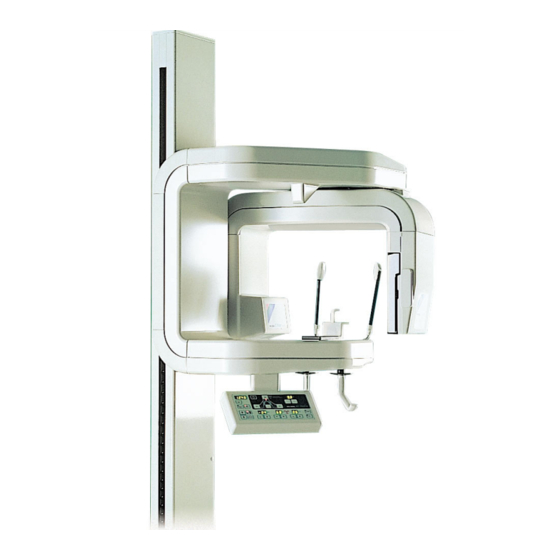
Planmeca Proline EC
pan/ceph/Dimax3
TECHNICAL MANUAL
Publication part number 688403
Version 27
Published 2005-06
En
Table of
Contents
Previous
Page
Next
Page
1
2
3
4
5
Advertisement
Table of Contents
Need help?
Do you have a question about the Proline EC pan and is the answer not in the manual?
Ask a question
Questions and answers
Related Manuals for Planmeca Proline EC pan
Medical Equipment Planmeca Proline XC User Manual
Cephalostat (30 pages)
Medical Equipment Planmeca proline xc Installation Manual
(52 pages)
Medical Equipment Planmeca Proline XC Technical Manual
(258 pages)
Medical Equipment Planmeca Proline EC Panoramic User Manual
(60 pages)
Medical Equipment Planmeca Proline XC Pan Calibration Manual
(42 pages)
Medical Equipment Planmeca ProSensor User Manual
Digital radiography system (28 pages)
Medical Equipment Planmeca ProMax User Manual
Cephalostat (42 pages)
Medical Equipment Planmeca ProMax Technical Manual
(378 pages)
Medical Equipment Planmeca ProMax User Manual
3d max with protouch (66 pages)
Medical Equipment Planmeca ProMax Installation Instructions Manual
(20 pages)
Medical Equipment Planmeca ProX User Manual
(58 pages)
Medical Equipment Planmeca ProOne Technical Manual
(195 pages)
Medical Equipment Planmeca ProOne User Manual
(70 pages)
Medical Equipment Planmeca ProOne User Manual
(116 pages)
Medical Equipment Planmeca ProOne Installation Manual
(48 pages)
Medical Equipment Planmeca Prostyle Intra User Manual
(33 pages)
This manual is also suitable for:
Proline ec ceph
Proline ec dimax3
Table of Contents
Save PDF
Print
Rename the bookmark
Delete bookmark?
Delete from my manuals?
Login
Sign In
OR
Sign in with Facebook
Sign in with Google
Upload manual
Upload from disk
Upload from URL


Need help?
Do you have a question about the Proline EC pan and is the answer not in the manual?
Questions and answers