
Related Manuals for Multitech CommPlete 4000 Series


Summary of Contents for Multitech CommPlete 4000 Series
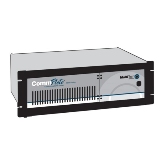
- Page 1 All manuals and user guides at all-guides.com CommPlete 4000 Communications Server User Guide...
- Page 2 MultiExpressFax, and the Multi-Tech logo. CompuServe is a trademark of CompuServe, Inc. Multi-Tech Systems, Inc. 2205 Woodale Drive Mounds View, Minnesota 55112 (612) 785-3500 or (800) 328-9717 Fax (612) 785-9874 Tech Support (800) 972-2439 Internet Address: http://www.multitech.com CommPlete 4000 Communications Server Overview...
-
Page 3: Table Of Contents
All manuals and user guides at all-guides.com Contents 1 System Overview Introduction ............................6 Product Overview ..........................6 RASExpress V5.31 ..........................6 Documentation Set Overview ......................7 Technical Specifications ........................8 Chassis ............................8 Power Supply ........................... 8 AC Input ............................8 DC Output ............................ - Page 4 All manuals and user guides at all-guides.com Limited Warranty ..........................38 Tech Support ..........................38 Recording CommPlete 4000 Information ..................38 Service ............................39 About the Multi-Tech BBS ......................... 39 How to Use the Multi-Tech BBS ....................39 About the Internet ........................... 40 About the Multi-Tech Fax-Back Service ....................
-
Page 5: System Overview
All manuals and user guides at all-guides.com 1 System Overview CommPlete 4000 Communications Server Overview... -
Page 6: Introduction
All manuals and user guides at all-guides.com System Overview Introduction The CommPlete™ 4000 Communications Server is a single-segment, rack mountable communications server. It is customized for dedicated turnkey operation of LAN-based communications and remote access server functions. The CommPlete 4000 is a general purpose, turnkey communications server that easily interfaces to any existing Novell, Windows NT, or IP network. -
Page 7: Documentation Set Overview
All manuals and user guides at all-guides.com RASExpress The CommPlete 4000 is equipped with factory installed RASExpress, an advanced remote access software that enables network managers to configure and manage remote servers via web browsers, through Telnet over an IP network, and via a GUI manager over both IP and IPX networks. -
Page 8: Technical Specifications
Note: 3.3 volts, DC, is available at PCI expansion slots on one side of the backplane only. This does not affect MultiTech ISI cards because they do not require 3.3-volts from the backplane. However, PCI expansion cards made by some other manufacturers may require3.3 volts. Any such boards must be installed in the CommPlete 4000 backplane on the side of the chassis where the Single-Board Computer is located. -
Page 9: Dimensions
All manuals and user guides at all-guides.com side of the backplane, such PCI expansion cards will not operate properly in those positions. Dimensions • Height: 5.25 inches • Width: 19 inches • Depth: 17 inches • Weight: 31 lbs. (14kg) Environmental •... - Page 10 All manuals and user guides at all-guides.com CommPlete 4000 Communications Server Overview...
-
Page 11: Installing Your Commplete 4000
All manuals and user guides at all-guides.com 2 Installing Your CommPlete 4000 CommPlete 4000 Communications Server Overview... -
Page 12: Introduction
All manuals and user guides at all-guides.com Introduction This chapter explains how to set up and connect cables for the CommPlete 4000. This product is ready to be connected to the end-user's Ethernet concentrator. It is preconfigured to operate as a communications server. The operator must make modem/terminal-adapter connections, link up the VGA monitor and keyboard, boot the system, and enter some basic information. -
Page 13: Sbc Board Cabling
All manuals and user guides at all-guides.com If the ISIHP-4S or -4U are used, each ISIHP card accepts as many as four RJ-45 connectors to accommodate ISDN BRI lines. (The modem connections that accommodate analog calls are internal to the ISIHP board. That is, when the V.90 modem module is installed, each ISDN B- channel connects to a V.90 modem via a digital connection. -
Page 14: Isi Board Cabling
Consequently, if both slots are used, they must be occupied with identical devices (and the device drivers must be identical). This is a constraint of PCI bus architecture. Also, the device drivers must support “interrupt-sharing.” The drivers for the MultiTech ISI card do support interrupt-sharing Shared Interrupt for Top Slots. -
Page 15: Nic Cabling
All manuals and user guides at all-guides.com Shipped Configuration Preferred expansion slots Installing expansion card here requires removal of card cage. Figure 2-3c. Convenience of using outer expansion slots before the inner slot NIC Cabling The 10/100Mb PCI EtherNet Network Interface Card is located as shown in Figure 2-4. The NIC has a single RJ-45 connector and three LEDs. -
Page 16: Powering Up
All manuals and user guides at all-guides.com CommPlete 4000 Communications Server Overview... -
Page 17: Getting Started With Rasexpress
All manuals and user guides at all-guides.com 3 Getting Started with RASExpress CommPlete 4000 Communications Server Overview... -
Page 18: Quick Start With Rasexpress
All manuals and user guides at all-guides.com Quick Start with RASExpress MultiTech Systems has preinstalled RASExpress server software on your CommPlete 4000 to make configuration as simple as possible. For your convenience, a copy of the RASExpress Installation program is on the CD-ROM shipped with the CommPlete 4000. Complete the procedure below to put your CommPlete 4000 into operation as a Remote Access Server. - Page 19 All manuals and user guides at all-guides.com A2. Using the provided RS-232C serial cable, connect a terminal (or an auxiliary PC) to the CommPlete 4000’s serial port. Connect RS-232C Serial Cable (female end) here Backplane COM 1 15-Pin Video DB9 male Connector (to External Display Monitor)
- Page 20 All manuals and user guides at all-guides.com A14. If you set the Remote Client IP Address field to the value Configure Per Port, follow these steps when this present Quick Configuration procedure is done: i. From the terminal main menu, select Configuration of server ii.
- Page 21 All manuals and user guides at all-guides.com Connect RS-232C Serial Cable (female end) here Backplane COM 1 15-Pin Video Connector DB9 male (to External Display Monitor) 6-Pin Circular Jack (To External Keyboard) 232C Cable Dumb Terminal Auxiliary PC Figure 3-2: Serial port on the CommPlete 4000 B3.
- Page 22 B11. At the Telnet main menu, select Configuration of server. B12. Set network parameters as described in items A9 through A17 in Method A above. Information on the MultiTech auxiliary software packages for authentication and workstation redirection (RADIUS, WINMCSI, and MCSIWSN) can be found in the appendices of the CommPlete 4000 Quick Start Guide and in the RADIUS Server User Guide.
-
Page 23: Hardware Removal/Replacement
All manuals and user guides at all-guides.com 4 Hardware removal/ Replacement CommPlete 4000 Communications Server Overview... -
Page 24: Introduction
All manuals and user guides at all-guides.com Introduction This chapter’s procedures describe removal and replacement of the main hardware components of the CommPlete 4000. Before removing or replacing any component, disconnect the cables from the back of the CommPlete 4000 and remove the CommPlete 4000 from its rack enclosure per instructions. -
Page 25: Card Cage Removal/Replacement
All manuals and user guides at all-guides.com 6 To re-attach cables and re-mount the CommPlete 4000, follow steps 1-5 in reverse order and sense. That is, a. (Two people are needed.) Attach the CommPlete 4000 to its rack enclosure using the four mounting screws. - Page 26 All manuals and user guides at all-guides.com C h a s s i s M o u n t i n g S c r e w s Fig. 4-4. Chassis Mounting Screw 4 Finish pulling the card cage (including fan enclosure) straight up and out of the chassis. See Figure 4-5.
-
Page 27: Board Removal And Replacement
All manuals and user guides at all-guides.com B la c k B la c k B lu e Y e ll o w B la c k B la c k B l a c k B l a c k B l u e Y e l l o w B l a c k... -
Page 28: Removing Nic Board
All manuals and user guides at all-guides.com COM 1 Mouse COM 2 Connector KBL JP6 EXKB Printer Port Flash Connector Disk JP11 Real Time Clock Floppy Drive BIOS Connector Flash BIOS Chipset Hard Drive Connector 6xx86 Fanned Heatsink Location Chipset SIMM 1 SIMM 2 SIMM 3... -
Page 29: Removing Isi Boards
All manuals and user guides at all-guides.com 2 Remove the top cover from the CommPlete 4000 by removing the seven cover mounting screws located in the back of the CommPlete 4000. See figure 4-3. 3 Remove the two chassis mounting screws from the card cage. See figure 4-4. 4 Being careful to maintain slack in the power cables, lift the card cage up and over so that it rests along side the chassis. -
Page 30: Hard Disk Drive Removal/Replacement
All manuals and user guides at all-guides.com d. Replace top cover (7 screws). e. (Two people are needed.) Replace CommPlete 4000 into rack enclosure. Hard Disk Drive Removal/Replacement 1 Remove the CommPlete 4000 from rack enclosure (two people are needed). Follow the procedure “Disconnecting Cables and Removal from Enclosure”... -
Page 31: Cdrom Removal/Replacement
All manuals and user guides at all-guides.com Note: Before installing card cage, make sure power connectors from power supply to midplane are fully connected (Figure 4-5b). d. Re-install the card cage and attach it to chassis (2 screws). e. Replace top cover (7 screws). f. - Page 32 All manuals and user guides at all-guides.com 4 Partially remove the card cage and remove power cabling at midplane. 5 Remove the power connection from the fanned heatsinkon the SBC (Figure 4-6). 6 Remove power cables from the back of hard drive, floppy drive, and CD ROM drive. 7 Remove the screw that holds the ground wire by the power switch.
-
Page 33: Troubleshooting
All manuals and user guides at all-guides.com 5 Troubleshooting CommPlete 4000 Communications Server Overview... -
Page 34: Introduction
— If problem persists, contact MultiTech's Technical Support department (see Chapter 6). • SBC does not boot correctly or hangs after video appears — Run BIOS Setup Utility to verify correct configuration for system and drives (press DEL as system boots). -
Page 35: Diagnostic Tests
All manuals and user guides at all-guides.com — If problem persists, contact MultiTech's Technical Support department (see Chapter 6). • COM1, COM2, or LPT1 port does not respond correctly — Try COM2. If it also fails, check Setup configuration and verify that the ports are enabled. - Page 36 All manuals and user guides at all-guides.com CommPlete 4000 Communications Server Overview...
-
Page 37: Service, Warranty, And Technical Support
All manuals and user guides at all-guides.com 6 Service, Warranty, and Technical Support CommPlete 4000 Communications Server Overview... -
Page 38: Introduction
All manuals and user guides at all-guides.com Service, Warranty, and Technical Support Introduction This chapter starts out with statements about your CommPlete 4000's 2-year warranty. The next section, Tech Support, should be read carefully if you have questions or problems with your CommPlete 4000. -
Page 39: Service
All manuals and user guides at all-guides.com Service If your tech support specialist decides that service is required, your CommPlete 4000 may be sent (freight prepaid) to our factory. Return shipping charges will be paid by Multi-Tech Systems. Include the following with your CommPlete 4000: •... -
Page 40: About The Internet
Multi-Tech is a commercial user on the Internet, and we retrieve e-mail messages from on a periodic basis. If you prefer to receive e-mail technical support via the Internet, you can contact Tech Support at the following address: http://www.multitech.com/_forms/email_tech_support.htm Multi-Tech's presence includes a Web site at: http://www.multitech.com and an ftp site at: ftp://ftp.multitech.com... -
Page 41: Appendices
All manuals and user guides at all-guides.com Appendices CommPlete 4000 Communications Server Overview... -
Page 42: Appendix A—Back Panel Connector Pinouts
All manuals and user guides at all-guides.com Appendix A—Back Panel Connector Pinouts This appendix provides specifications for the various connectors on the back panel of the MiniArray. VGA 15-Pin Connector This connector provides video analog data and horizontal and vertical synchronization signals for VGA monitors. -
Page 43: 6-Pin Circular Jack
All manuals and user guides at all-guides.com Pin Identification Description RX Data TX Data Ground 6-Pin Circular Jack This connector connects the keyboard to the SBC board. Figure A-3. 6-Pin Mini-DIN Keyboard Connector Pin Identification PinDescription +Keyboard Data +5V DC +Keyboard Clock RJ-45 Connector This connector ties the EN-Series Ethernet board to a 10BASET network. -
Page 44: 34-Pin Floppy Disk Drive Connector
All manuals and user guides at all-guides.com No Connect No Connect 34-Pin Floppy Disk Drive Connector This connector provides signal and data connection between the floppy drive and the SBC board. Figure A-4. Floppy Disk Connector Description Description Ground Direction (Stepper Motor) RPM/RWC Ground Ground... -
Page 45: Printer Port Connector
All manuals and user guides at all-guides.com COM 2 Port Connector This 10-pin connector transfers serial data to and from the COM 2 port. Figure A-6. COM 2 Port Connector PinSignal Name (Direction) Carrier Detect (Input) Data Set Ready (Input) Receive Data (Input) Request To Send (Output) Transmit Data (Output) -
Page 46: Appendix B—Regulatory Information
All manuals and user guides at all-guides.com Appendix B—Regulatory Information FCC Regulations for Telephone Line Interconnection 1. This equipment complies with Part 68 of the Federal Communications Commission (FCC) rules. On the outside surface of this equipment is a label that contains, among other information, the FCC registration number and ringer equivalence number (REN). -
Page 47: Canadian Limitations Notice
All manuals and user guides at all-guides.com Canadian Limitations Notice Notice: The ringer equivalence number (REN) assigned to each terminal device provides an indication of the maximum number of terminals allowed to be connected to a telephone interface. The termination of a interface may consist of any combination of devices subject only to the requirement that the sum of the ringer equivalence numbers of all the devices does not exceed 5. - Page 48 All manuals and user guides at all-guides.com conductive pollution or dry nonconductive pollution which could become conductive due to condensation. Failure to maintain these minimum distances would invalidate approval. a t l t a r ) 8 . ) 8 . ) 0 .
-
Page 49: European Low Voltage Directive
All manuals and user guides at all-guides.com • Modem • PBX timed break register recall European Low Voltage Directive When correctly installed and maintained, the modem will present no hazard to the user. When correctly installed, the modem will be connected to the PSTN or a PW and to a Data Terminal Equipment (DTE) whose modem connections comply with CCITT recommendation V28. -
Page 50: Compliance With Bs6328 Part 1
All manuals and user guides at all-guides.com c. Users are advised to check the numbers entered during the Auto Call set up phase prior to dialing. d. The user should not issue any sequence of commands to the modem which would cause the modem to exceed the maximum allowable pause of 8 seconds from the time the modem goes off hook until dialing begins.
Need help?
Do you have a question about the CommPlete 4000 Series and is the answer not in the manual?
Questions and answers