MacDon M1240 Unloading And Assembly Instructions
Self-propelled windrower
Hide thumbs
Also See for M1240:
- Operator's manual (488 pages) ,
- Unloading and assembly instructions (170 pages) ,
- Software update instructions (52 pages)

Related Manuals for MacDon M1240


Summary of Contents for MacDon M1240
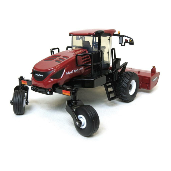
- Page 1 M1240 Self-Propelled Windrower Unloading and Assembly Instructions (North America) 214056 Revision A 2017 Model Year Original Instruction The harvesting specialists.
- Page 2 ® ™ M1240 Self-Propelled Windrower, featuring Dual Direction and Crossflex rear suspension Published November 2016...
- Page 3 This manual contains unloading, assembly, and predelivery information for the MacDon M1240 Self-Propelled Windrower, which when coupled with one of MacDon’s auger or draper headers, provides a package designed to cut and lay a variety of grain, hay, and specialty crops in windrows.
-
Page 5: Table Of Contents
TABLE OF CONTENTS Introduction ............................i Safety ..............................1 Signal Words........................... 1 General Safety ..........................2 Battery Safety..........................4 Safety Signs ............................ 5 Unloading the Windrower........................7 Using One Forklift to Unload Windrower .................... 7 Assembling the Windrower ........................9 Repositioning Right Leg ........................ - Page 6 TABLE OF CONTENTS Navigating the Harvest Performance Tracker..............79 Setting Display Language and Units of Measure ............... 80 Setting Display Time and Date..................81 Setting Windrower Tire Size .................... 82 Checking Header Settings ....................82 5.2.2 Checking Engine Speed ......................83 5.2.3 Checking Exterior Lights ......................
-
Page 7: Safety
1 Safety 1.1 Signal Words Three signal words, DANGER, WARNING, and CAUTION, are used to alert you to hazardous situations. The appropriate signal word for each situation has been selected using the following guidelines: DANGER Indicates an imminently hazardous situation that, if not avoided, will result in death or serious injury. WARNING Indicates a potentially hazardous situation that, if not avoided, could result in death or serious injury. -
Page 8: General Safety
SAFETY 1.2 General Safety CAUTION The following are general farm safety precautions that should be part of your operating procedure for all types of machinery. Protect yourself. • When assembling, operating, and servicing machinery, wear all protective clothing and personal safety devices that could be necessary for job at hand. - Page 9 SAFETY • Wear close-fitting clothing and cover long hair. Never wear dangling items such as scarves or bracelets. • Keep all shields in place. NEVER alter or remove safety equipment. Make sure driveline guards can rotate independently of shaft and can telescope freely. •...
-
Page 10: Battery Safety
SAFETY 1.3 Battery Safety WARNING • Keep all sparks and flames away from batteries, as a gas given off by electrolyte is explosive. • Ventilate when charging in enclosed space. Figure 1.7: Safety around Batteries WARNING • Wear safety glasses when working near batteries. •... -
Page 11: Safety Signs
• If original parts on which a safety sign was installed are replaced, be sure repair part also bears current safety sign. • Safety signs are available from your MacDon Dealer. Figure 1.10: Operator’s Manual Decal 214056 Revision A... -
Page 13: Unloading The Windrower
2 Unloading the Windrower 2.1 Using One Forklift to Unload Windrower CAUTION Equipment used for unloading must meet or exceed the specified requirements. Using inadequate equipment may result in chain breakage, vehicle tipping, or machine damage. Table 2.1 Lifting Vehicle Requirements Minimum Capacity 7037 kg (15,500 lb.) Minimum Fork Length... -
Page 15: Assembling The Windrower
3 Assembling the Windrower Perform all procedures in this chapter in the order in which they are listed. 3.1 Repositioning Right Leg The right (cab-forward) leg requires repositioning from shipping to field configuration. CAUTION Do NOT open the right cab-forward door when the right leg is in shipping configuration. If glass door contacts the leg, it may result in broken glass door and/or damaged door seal. - Page 16 ASSEMBLING THE WINDROWER 4. Adjust jack height until pin (A) is loose. Extract pin from front of frame with a slide hammer (MD #209816) (B) (tool required due to limited space in front of fuel tank). Instructions are included with the tool. NOTE: Removing the pins will be difficult if the jack is not properly positioned to take the weight off the leg.
-
Page 17: Installing Drive Wheels
ASSEMBLING THE WINDROWER 3.2 Installing Drive Wheels 1. Clean mount surface on wheel drive and rim. 2. Position drive wheel (A) against the wheel drive hub (B) so the air valve (C) is on the outside and the tire tread (D) points forward with the windrower in cab-forward orientation. -
Page 18: Installing Caster Wheels
ASSEMBLING THE WINDROWER 3.3 Installing Caster Wheels Some shipping configurations come with caster wheels removed. Follow this procedure to install caster wheels if requried. 1. Support rear of windrower on a stand so that it is approximately level. Stand must be capable of supporting a minimum of 2630 kg (5800 lb.). -
Page 19: Repositioning Walking Beam And Installing Caster Wheel Shocks
ASSEMBLING THE WINDROWER 3.4 Repositioning Walking Beam and Installing Caster Wheel Shocks A narrow walking beam tread width is better suited for smaller headers because it allows more space for the uncut crop and provides more maneuverability around poles, irrigation inlets, and other obstacles. A wider walking beam tread width reduces runover in heavy crops that produce large windrows. - Page 20 ASSEMBLING THE WINDROWER 7. Place support brackets (A) onto walking beam as shown and secure with two M24 x 60 bolts coated with anti-seize compound and M24 flat washers (B). Do NOT fully tighten. Figure 3.14: Anti-Shimmy Brackets 8. Tighten bolts as follows: a.
- Page 21 ASSEMBLING THE WINDROWER 10. Lower windrower to ground. 11. Retrieve caster shock absorbers and hardware from bag in toolbox. NOTE: Use ignition key to unlock toolbox compartment. 12. Attach barrel end of shock absorber (A) to forward hole in support (B) with one M16 x 75 flange head bolt (C) and one M16 tech lock nut (D).
-
Page 22: Lowering Steps
ASSEMBLING THE WINDROWER 3.5 Lowering Steps Lower steps from shipping position to working position as follows: left side shown, right side opposite. 1. Remove stop bolt (A) and discard. 2. Loosen pivot bolts (B) at both sides of step (C). Figure 3.20: Left Step –... -
Page 23: Installing Windshield Access Step
ASSEMBLING THE WINDROWER 3.6 Installing Windshield Access Step The windshield access step is secured on the railing of the right-hand side platform (cab-forward). 1. Remove windshield access step (A) from shipping location on right platform, and remove packing materials (B) from step and railing. 2. -
Page 24: Positioning Mirror Arms
ASSEMBLING THE WINDROWER 3.7 Positioning Mirror Arms The mirror/light support arms require repositioning from shipping position to working position. 1. Loosen retaining nut (A) and pivot nut (B) on support arm (C). 2. Swivel support arm (C) forward 90 degrees from shipping position to working position. -
Page 25: Installing Slow Moving Vehicle (Smv) Signs
ASSEMBLING THE WINDROWER 3.8 Installing Slow Moving Vehicle (SMV) Signs To install the SMV sign onto the mirror/light support and walking beam, proceed as follows: 1. Retrieve SMV signs from inside cab and hardware from toolbox. NOTE: Use ignition key to unlock cab door and toolbox compartment. 2. -
Page 26: Replacing Speed Identification Symbol (Sis) Decal (Us Only)
ASSEMBLING THE WINDROWER 3.9 Replacing Speed Identification Symbol (SIS) Decal (US Only) This topic applies to windrowers used in the United States only. 1. Locate the existing SIS decal bracket on the left mirror/lighting arm. 2. Wipe the existing decal with a clean cloth to remove dirt and grease. -
Page 27: Installing Rear Ballast Package
ASSEMBLING THE WINDROWER 3.10 Installing Rear Ballast Package When windrower operates with a heavy header, ballast needs to be added to the aft end. Use the following table to determine the amount of ballast required. Table 3.1 Ballast Additional Header Additional Description Options... - Page 28 ASSEMBLING THE WINDROWER To install rear ballast, follow these steps: DANGER To avoid bodily injury or death from unexpected startup of the machine, always stop the engine and remove the key from the ignition before leaving the operator’s seat for any reason. 1.
- Page 29 ASSEMBLING THE WINDROWER 7. Separate bezel assembly (A) by removing six fasteners (B). 8. Store center portion of assembly for reinstallation if desired. Figure 3.31: Bezel Assembly CAUTION To avoid injury, keep fingers clear of weight bracket when installing weights. 9.
- Page 30 ASSEMBLING THE WINDROWER Figure 3.34: Three Sets: 489 kg (1080 lb.) 12. Attach left side bezel (A) to frame with four screws (B). 13. Attach right side bezel (C) with four screws. Figure 3.35: Rear Light Bezel 14. Grasp the hood by louver (A) and lower until hood engages latch.
-
Page 31: Lubricating The Windrower
ASSEMBLING THE WINDROWER 3.11 Lubricating the Windrower For grease specification, refer to 6.1 Lubricants, Fluids, and System Capacities, page 3.11.1 Lubrication Procedure DANGER To avoid bodily injury or death from unexpected startup of the machine, always stop the engine and remove the key from the ignition before leaving the operator’s seat for any reason. -
Page 32: Connecting Batteries
ASSEMBLING THE WINDROWER 3.12 Connecting Batteries 1. Move latch (A) towards right cab-forward side of the windrower. 2. Using a louver (B), lift the hood to open. Figure 3.38: Engine Compartment Hood 3. Lift up on the cab end of the cover (A) to disengage it from the retaining tab (B), and swing cover away from the frame. - Page 33 ASSEMBLING THE WINDROWER 7. Swing the cover (A) towards the windrower frame. Lift up on the cab end of the cover until it is secured by the retaining tab (B) on the frame. 8. Grasp the hood by the louver (C) and lower until hood engages latch.
-
Page 34: Starting The Engine
ASSEMBLING THE WINDROWER 3.13 Starting the Engine DANGER • Avoid possible injury or death from a runaway machine. • This machine has safety devices which allow the engine to start only when the ground speed lever is in PARK, the steering wheel is locked in the NEUTRAL position, and the HEADER ENGAGE switch is in the OFF position. - Page 35 ASSEMBLING THE WINDROWER 6. Turn IGNITION switch (A) to the ON position, and the Harvest Performance Tracker (HPT) (B) will illuminate. If HPT is still booting up, wait for Wait to Start (WTS) symbol (C) to disappear before trying to start engine. 7.
- Page 36 ASSEMBLING THE WINDROWER NOTE: When the engine temperature is below 5°C (40°F), the engine will cycle through a period where it appears to labor until the engine warms up. Do NOT operate engine above 1500 rpm until the HPT engine temperature gauge is above the blue range (A).
-
Page 37: Attaching Headers To M1 Series Windrower
4 Attaching Headers to M1 Series Windrower 4.1 A40 D Auger Header 4.1.1 Attaching an A40 D Auger Header This procedure is for 2017 and newer A40 D headers equipped with the Auger Header Compatibility kit (B5998). CAUTION To avoid bodily injury or death from unexpected startup of machine, always stop engine and remove key from ignition before leaving operator’s seat for any reason. - Page 38 ATTACHING HEADERS TO M1 SERIES WINDROWER 3. Press HPT scroll knob (A) to highlight QuickMenu options. 4. Rotate HPT scroll knob (A) to highlight the HEADER FLOAT symbol (B) and press to select. Figure 4.3: HPT Display 5. On Float Adjust page, press soft key 3 (A) to remove float.
- Page 39 ATTACHING HEADERS TO M1 SERIES WINDROWER 8. For hydraulic center-link without self-alignment: Relocate pin (A) in frame linkage as required to raise the center-link (B) until the hook is above the attachment pin on the header. IMPORTANT: If the center-link is too low, it may contact the header as the windrower approaches the header for hookup.
- Page 40 ATTACHING HEADERS TO M1 SERIES WINDROWER CAUTION Check to be sure all bystanders have cleared the area. 14. Press the HEADER UP switch (A) to raise header to maximum height. NOTE: If one end of the header does NOT fully raise, rephase the lift cylinders as follows: a.
- Page 41 ATTACHING HEADERS TO M1 SERIES WINDROWER 18. Remove lynch pin from clevis pin (A) in stand (B). 19. Hold stand (B) and remove pin (A). 20. Move stand to storage position by inverting and relocating onto bracket as shown. Reinsert clevis pin (A) and secure with lynch pin.
-
Page 42: Connecting A40 D Hydraulics
ATTACHING HEADERS TO M1 SERIES WINDROWER NOTE: If not prompted by the HPT display to restore header float, restore header float manually by doing the following: 24. Press rotary scroll knob (A) on HPT to highlight QuickMenu options. 25. Rotate scroll knob (A) to highlight the HEADER FLOAT symbol (B) and press scroll knob to select. - Page 43 ATTACHING HEADERS TO M1 SERIES WINDROWER 3. Retrieve hydraulic multicouplers (A) and electrical harness (B) from the header. 4. Route hose/harness bundle toward the windrower through support (C). Figure 4.18: Hydraulics Hoses in Storage Position 5. Insert hose support (A) into hole in the windrower left leg, and route the header hose bundle (B) under the windrower to the hydraulic and electrical couplers.
-
Page 44: Detaching An A40 D Auger Header
ATTACHING HEADERS TO M1 SERIES WINDROWER 11. Remove cover from receptacle (A), and connect electrical harness from header. Figure 4.21: Electrical Connectors 12. Push latch (A) to unlock the platform (B). Figure 4.22: Platform: Open 13. Push platform (A) towards the cab until it stops and latch engages. - Page 45 ATTACHING HEADERS TO M1 SERIES WINDROWER DANGER To avoid bodily injury from fall of raised header, always engage safety props when working on or around raised header, and before going under header for any reason. 1. Start engine and press header up button (A) on ground speed lever (GSL) to raise header to maximum height.
- Page 46 ATTACHING HEADERS TO M1 SERIES WINDROWER 6. Lower stand (A) by pulling clevis pin (B), inverting stand, and relocating on bracket. Reinsert pin (B) and secure with hairpin. Figure 4.27: Header Stand CAUTION Check to be sure all bystanders have cleared the area. 7.
- Page 47 ATTACHING HEADERS TO M1 SERIES WINDROWER 10. Stop engine and remove key from ignition. 11. Lift hook release (A) and lift hook (B) off header pin. NOTE: If optional center-link self-alignment kit is installed, lift release (C) and then operate the link lift cylinder with the REEL UP switch on the GSL to disengage the center-link from the header.
- Page 48 ATTACHING HEADERS TO M1 SERIES WINDROWER 15. Reinstall clevis pin (B) into header support (C) and secure with hairpin (A). Repeat for opposite side. Figure 4.33: Header Support 214056 Revision A...
-
Page 49: D1X Or D1Xl Series Header
ATTACHING HEADERS TO M1 SERIES WINDROWER 4.2 D1X or D1XL Series Header 4.2.1 Attaching Draper Header Supports Draper header supports are required to attach a D1X or D1XL Series Draper Header to the windrower. DANGER To avoid bodily injury or death from unexpected startup of the machine, always stop the engine and remove the key from the ignition before leaving the operator’s seat for any reason. - Page 50 ATTACHING HEADERS TO M1 SERIES WINDROWER 1. For hydraulic center-link without self-alignment: Relocate pin (A) in frame linkage as required to raise the center-link (B) until the hook is above the attachment pin on the header. IMPORTANT: If the center-link is too low, it may contact the header as the windrower approaches the header for hookup.
- Page 51 ATTACHING HEADERS TO M1 SERIES WINDROWER 4. Press scroll knob (A) on HPT to display the QuickMenu system. 5. Rotate scroll knob (A) to highlight the HEADER FLOAT symbol (B) and press scroll knob to select. Figure 4.39: HPT Display 6.
- Page 52 ATTACHING HEADERS TO M1 SERIES WINDROWER 8. Drive the windrower slowly forward until the draper header supports (A) enter the header legs (B). Continue driving slowly forward until lift linkages contact the support plates in the header legs and the header nudges forward.
- Page 53 ATTACHING HEADERS TO M1 SERIES WINDROWER 11. For hydraulic center-link without self-alignment: a. Press HEADER TILT UP or HEADER TILT DOWN cylinder switches on the GSL to extend or retract center-link cylinder until the hook is aligned with the header attachment pin. b.
- Page 54 ATTACHING HEADERS TO M1 SERIES WINDROWER 15. Install pin (B) through the header leg (engaging U-bracket in draper header support) on both sides and secure with a hairpin (A). 16. Raise header stand (D) to storage position by pulling spring pin (C) and lifting stand into uppermost position. Release spring pin.
-
Page 55: Connecting D1X Or D1Xl Series Hydraulics
ATTACHING HEADERS TO M1 SERIES WINDROWER NOTE: If not prompted by the HPT display to restore header float, restore header float manually by doing the following: 20. Press rotary scroll knob (A) on Harvest Performance Tracker (HPT) to highlight QuickMenu options. 21. - Page 56 ATTACHING HEADERS TO M1 SERIES WINDROWER 1. Pull handle (A) on hose management arm (B) rearwards to disengage arm from support (C). 2. Move arm (B) toward left cab-forward side of windrower. Figure 4.52: Hydraulic Hose Management Arm 3. Ensure cab door is closed on the left cab-forward side of the windrower.
- Page 57 ATTACHING HEADERS TO M1 SERIES WINDROWER 7. Retrieve draper drive and reel control multicoupler (A) from hose management arm. 8. Push knob (B) on hydraulic receptacle and pull handle (C) fully away from windrower. 9. Open cover (D) and position coupler onto receptacle. Align pins in coupler with slots in handle (C) and push handle toward windrower so that coupler is locked onto receptacle and knob (B) snaps out.
-
Page 58: Detaching A D1X Or D1Xl Series Header
ATTACHING HEADERS TO M1 SERIES WINDROWER 17. Ensure hydraulic hose routing is as straight as possible and avoids potential rub/wear points. Figure 4.58: Hydraulic Multicouplers and Hose Routing 4.2.4 Detaching a D1X or D1XL Series Header DANGER To avoid bodily injury or death from unexpected startup of the machine, always stop the engine and remove the key from the ignition before leaving the operator’s seat for any reason. - Page 59 ATTACHING HEADERS TO M1 SERIES WINDROWER NOTE: Firmly hold handle (B) when disconnecting the multicoupler (C). Pressure may cause the handle to kick back with force. 6. Push lock button (A) and pull handle (B) to disengage multicoupler (C) and disconnect the hydraulics from the rear knife/reel drive receptacle.
- Page 60 ATTACHING HEADERS TO M1 SERIES WINDROWER 15. Disconnect hose management arm (A) from windrower by pulling latch lever (B) to open latch. Keep latch open and move hose management arm (A) away from header with handle (C). Figure 4.63: Hose Management Arm 16.
- Page 61 ATTACHING HEADERS TO M1 SERIES WINDROWER Windrowers with self-aligning center-link: 19. Release the center-link latch (A) before returning to the cab. Figure 4.66: Center-Link 20. Disengage safety prop by turning lever (A) downwards until lever locks into the vertical position. 21.
- Page 62 ATTACHING HEADERS TO M1 SERIES WINDROWER Windrowers without self-aligning center-link: 28. Shut off the engine and remove the key. 29. Disconnect center-link by lifting release (B) and lift hook (A) off header. CAUTION Check to be sure all bystanders have cleared the area. 30.
-
Page 63: R85 16-Foot Header
ATTACHING HEADERS TO M1 SERIES WINDROWER 4.3 R85 16-Foot Header 4.3.1 Attaching an R85 16-Foot Header DANGER To avoid bodily injury or death from unexpected startup of the machine, always stop the engine and remove the key from the ignition before leaving the operator’s seat for any reason. 1. - Page 64 ATTACHING HEADERS TO M1 SERIES WINDROWER CAUTION To prevent damage to the header lift linkages when lowering header lift legs without a header or weight box attached to the windrower, ensure the float springs tension is fully released. Figure 4.73: Header Float Spring NOTE: If not prompted by the HPT display to remove header float, remove header float manually by doing the...
- Page 65 ATTACHING HEADERS TO M1 SERIES WINDROWER 7. Press HEADER DOWN switch (E) on the ground speed lever (GSL) to fully retract header lift cylinders. 8. For hydraulic center-link with self-alignment: Press the REEL UP switch (B) on the GSL to raise the center-link until the hook is above the attachment pin on the header.
- Page 66 ATTACHING HEADERS TO M1 SERIES WINDROWER 12. For hydraulic center-link without self-alignment: a. Press HEADER TILT UP or HEADER TILT DOWN cylinder switches on the GSL to extend or retract center-link cylinder until the hook is aligned with the header attachment pin. b.
- Page 67 ATTACHING HEADERS TO M1 SERIES WINDROWER 16. Install clevis pin (A) through support and foot and secure with hairpin (B). Repeat for opposite side. IMPORTANT: Ensure clevis pin (A) is fully inserted and hairpin is installed behind bracket. Figure 4.82: Header support 17.
- Page 68 ATTACHING HEADERS TO M1 SERIES WINDROWER NOTE: If not prompted by the HPT display to restore header float, restore header float manually by doing the following: 20. Press rotary scroll knob (A) on Harvest Performance Tracker (HPT) to highlight QuickMenu options. 21.
-
Page 69: Connecting R85 16-Foot Header Hydraulics
Refer to the following steps to attach the hydraulic hoses and electrical harness from the header to the windrower. Note that these steps are also included in the R85 rotary header operator’s manual. 1. Open the left side platform (A). Figure 4.87: M1240 Windrower 2. Route hose bundle (A) from header to under windrower frame. - Page 70 ATTACHING HEADERS TO M1 SERIES WINDROWER 4. Refer to the following to connect hydraulic hoses with quick disconnect fittings, and electrical connections to the windrower. If hoses are not equipped with quick-disconnect fittings, they can be attached directly to the windrower fittings. Proceed to Step 5., page a.
-
Page 71: Detaching R85 16-Foot Header
ATTACHING HEADERS TO M1 SERIES WINDROWER 4.3.3 Detaching R85 16-Foot Header DANGER To avoid bodily injury or death from unexpected startup of the machine, always stop the engine and remove the key from the ignition before leaving the operator’s seat for any reason. CAUTION Check to be sure all bystanders have cleared the area. - Page 72 ATTACHING HEADERS TO M1 SERIES WINDROWER 6. Remove hairpin (B) from clevis pin (A) and remove clevis pin from header support (C) on both sides of header. Figure 4.94: Header Supports 7. Engage safety prop on the windrower’s lift cylinder as follows: a.
- Page 73 ATTACHING HEADERS TO M1 SERIES WINDROWER 9. Disengage safety prop by turning lever (A) downwards until lever locks into the vertical position. 10. Repeat for the opposite side. Figure 4.97: Safety Props CAUTION Check to be sure all bystanders have cleared the area. 11.
- Page 74 ATTACHING HEADERS TO M1 SERIES WINDROWER 15. For windrowers without self-aligning center-link: Shut off the engine and remove the key. 16. Lift hook release (C) and lift hook (B) off header pin. CAUTION Check to be sure all bystanders have cleared the area. 17.
-
Page 75: Performing Predelivery Checks
5 Performing Predelivery Checks Perform all procedures in this chapter in the order in which they are listed. IMPORTANT: The machine is factory-set and should not require further adjustments; however, perform the following checks to ensure your machine operates at maximum performance. Adjustments should be made only if absolutely necessary and in accordance with the instructions in this manual. -
Page 76: Checking And Adding Wheel Drive Lubricant Level
For optimal performance, drive wheel (A) tire pressures are determined by tire type, header size, and additional options. Refer to Table M1240 Tire Inflation Recommendations, page Caster Wheel Tires: Inflate all caster wheel (B) tires to 110 kPa (16 psi). - Page 77 PERFORMING PREDELIVERY CHECKS Table 5.1 M1240 Tire Inflation Recommendations Pressure Header Type Description Options Weight Kit Tire Type kPa (psi) Draper Header 159 (23) D125X 25-foot, double knife, — — single reel timed Turf 159 (26) 200 (29) 30-foot, double knife,...
-
Page 78: Checking Engine Air Intake
PERFORMING PREDELIVERY CHECKS Pressure Header Type Description Options Weight Kit Tire Type kPa (psi) Rotary Disc Header — 179 (26) 16-foot — — Turf 179 (26) Auger Header — 179 (26) — A40 D 16-foot — Turf 159 (23) — 179 (26) A40 D 18-foot... -
Page 79: Checking And Adding Hydraulic Oil
PERFORMING PREDELIVERY CHECKS 1. Operate the engine at low idle and check for leaks at the filter and drain plug. 2. Shut down the engine and remove the key. Wait about five minutes. 3. Remove the dipstick (A) by turning it counterclockwise to unlock. -
Page 80: Checking Fuel Separator
PERFORMING PREDELIVERY CHECKS 3. Locate the sight glass (A) that is provided on the right side of the tank. It indicates the oil level and any signs of contamination. NOTE: No oil in the sight glass indicates that the oil level is below the add mark on the dipstick. - Page 81 PERFORMING PREDELIVERY CHECKS 1. Move latch (A) towards right cab-forward side of the windrower. 2. Using a louver (B), lift the hood to open. Figure 5.11: Engine Compartment Hood 3. The tank has a MAX and MIN COLD line marker. Coolant level should be kept at the MAX COLD line (A).
-
Page 82: Checking Engine Gearbox Lubricant Level And Adding Lubricant
PERFORMING PREDELIVERY CHECKS 5.1.9 Checking Engine Gearbox Lubricant Level and Adding Lubricant 1. Remove check plug (A) on underside of windrower beneath the main pumps. The lubricant should be visible through the hole or slightly running out. 2. Add lubricant, if required, through the check plug hole (A) using a squeeze bottle, or by removing the breather at the top right side of the gearbox. - Page 83 PERFORMING PREDELIVERY CHECKS 3. With the engine running and the seat base is between locked positions, move the GSL out of PARK. Confirm the engine immediately shuts down and the HPT displays LOCK SEAT BASE and sounds a tone. 4. Shut down the engine and engage HEADER ENGAGE switch. Try starting the engine and confirm the HPT displays DISENGAGE HEADER.
-
Page 84: Performing Operational Checks
PERFORMING PREDELIVERY CHECKS 5.2 Performing Operational Checks 1. Perform the final checks and adjustments listed on the following pages and the Predelivery Checklist, page 111 (yellow sheet attached to this instruction) to ensure the machine is field-ready. 2. Ensure the Operator or the Dealer retains the completed Predelivery Checklist. 5.2.1 Checking Harvest Performance Display (HPT) 1. -
Page 85: Navigating The Harvest Performance Tracker
PERFORMING PREDELIVERY CHECKS Navigating the Harvest Performance Tracker Turning the scroll knob (A) on the Harvest Performance Tracker (HPT) highlights the available options within a menu and increases/decreases the available settings. Pushing the scroll knob selects functions or menu items. Scroll and select functions are duplicated on the ground speed lever (GSL) controls. -
Page 86: Setting Display Language And Units Of Measure
PERFORMING PREDELIVERY CHECKS 6. Press BACK button (A) on HPT to return to previous level within menu structure. 7. Press HOME button (B) on HPT to return to last selected run screen (or header disengaged screen). Figure 5.22: HPT Setting Display Language and Units of Measure 1. -
Page 87: Setting Display Time And Date
PERFORMING PREDELIVERY CHECKS Setting Display Time and Date Whenever the Harvest Performance Tracker (HPT) display boots up, the time and date will display according to your selected configuration. 1. Navigate to the SETTINGS Menu with soft key 5 and the HPT scroll knob. Refer to Navigating the Harvest Performance Tracker, page 79 if required. -
Page 88: Setting Windrower Tire Size
PERFORMING PREDELIVERY CHECKS Setting Windrower Tire Size The Harvest Performance Tracker (HPT) is factory-set for 600/65R28 bar tires. If the windrower has a different tire type, you need to change this setting. Setting the proper tire size is important for accurate tracking of ground speed, acres, and productivity data. -
Page 89: Checking Engine Speed
PERFORMING PREDELIVERY CHECKS 5.2.2 Checking Engine Speed 1. Move throttle to idle position. 2. Check engine speed (A) on Harvest Performance Tracker (HPT) display and compare to value in table. 3. Move throttle to maximum rpm position. Table 5.2 Engine Speed Idle Maximum (No Load) 1000 rpm... -
Page 90: Checking Exterior Lights
PERFORMING PREDELIVERY CHECKS 5.2.3 Checking Exterior Lights 1. For models with LED lighting: Remove plastic film from LED lighting. 2. Rotate operator’s seat to cab-forward mode. 3. Press FIELD LIGHT switch (A). 4. Check that front field lights (B), rear field lights (C), and rear swath lights (D) are functioning. - Page 91 PERFORMING PREDELIVERY CHECKS 5. Press ROAD LIGHT switch (A), and check that front road lights (B) and rear red tail/brake lights (C) are functioning. 6. Press HIGH/LOW switch (D), and check lights (B). 7. Press TURN SIGNAL switches (E) on console, and check amber lights (F).
- Page 92 PERFORMING PREDELIVERY CHECKS 10. Rotate operator’s seat to engine-forward mode. 11. Press ROAD LIGHT switch (A), and check that front road lights (B) and rear red tail/brake lights (C) are functioning. 12. Press HIGH/LOW switch (D) and check lights (B). 13.
-
Page 93: Checking Horn
PERFORMING PREDELIVERY CHECKS 16. Push BEACON SWITCH (A), and check that amber beacons (B) are functioning. 17. Press switch to shut off beacons. Figure 5.33: Beacons 5.2.4 Checking Horn 1. Push HORN button (A) and listen for horn. Figure 5.34: Horn Button 214056 Revision A... -
Page 94: Checking Interior Lights
PERFORMING PREDELIVERY CHECKS 5.2.5 Checking Interior Lights 1. Open cab door and check that interior light (A) illuminates. 2. Enter the cab and close door; light should go off. Figure 5.35: Ingress/Egress Lights 3. Turn IGNITION key to RUN position. 4. - Page 95 PERFORMING PREDELIVERY CHECKS 2. Press AUTO FAN switch (A) (LED light shows orange) and then press RED TEMPERATURE CONTROL switch (B) until warm air enters cab through vents. 3. Press BLUE TEMPERATURE CONTROL switch (C) until cool air is entering the cab. 4.
-
Page 96: Checking Manuals
PERFORMING PREDELIVERY CHECKS 5.3 Checking Manuals Manuals are stored in one of the manual storage cases (A) behind the operator’s seat. Figure 5.39: Manual Storage Case 1. Ensure the following manuals are included with the windrower: • Operator’s Manual • Parts Catalog •... -
Page 97: Performing Final Steps
PERFORMING PREDELIVERY CHECKS 5.4 Performing Final Steps 1. Remove plastic covering from Harvest Performance Tracker (HPT) and seats after predelivery checks are complete. 2. If there is an optional GPS kit included, locate bag inside the cab containing the kit, and install in accordance with the instructions included. -
Page 99: Reference
6 Reference 6.1 Lubricants, Fluids, and System Capacities CAUTION To avoid injury or death, do not allow ANY machine fluids to enter the body. Table 6.1 System Capacities Lubricant/Fluid Location Description Capacity Diesel exhaust Diesel exhaust 28 liters Must meet ISO 22241 requirements. fluid (DEF) fluid tank (7.5 US gallons) - Page 100 REFERENCE ® If Fleetguard ES Compleat is unavailable, use a coolant concentrate or prediluted coolant intended for use with heavy duty diesel engines and with a minimum of the following chemical and physical properties: • Provides cylinder cavitation protection according to fleet study run at or above 60% load capacity. •...
-
Page 101: Fuel Specifications
REFERENCE 6.2 Fuel Specifications Use only ultra low sulphur diesel (ULSD) from a reputable supplier. For most year-round service, No.2 ULSD fuel meeting ASTM specification D975 Grade S15 will provide good performance. Table 6.2 Fuel Specification Water and Sulphur Fuel Specification Sediment Cetane No. -
Page 102: Torque Specifications
REFERENCE 6.3 Torque Specifications The following tables provide correct torque values for various bolts, cap screws, and hydraulic fittings. • Tighten all bolts to torque values specified in charts (unless otherwise noted throughout this manual). • Replace hardware with same strength and grade of bolt. •... - Page 103 REFERENCE Table 6.4 Metric Class 8.8 Bolts and Class 9 Distorted Thread Nut Torque (ft·lbf) Torque (N·m) Nominal (*in·lbf) Size (A) Min. Max. Min. Max. 3-0.5 3.5-0.6 4-0.7 5-0.8 6-1.0 8-1.25 18.8 20.8 *167 *185 Figure 6.2: Bolt Grades 10-1.5 12-1.75 14-2.0 16-2.0...
- Page 104 REFERENCE Table 6.6 Metric Class 10.9 Bolts and Class 10 Distorted Thread Nut Torque (ft·lbf) Torque (N·m) Nominal (*in·lbf) Size (A) Min. Max. Min. Max. 3-0.5 3.5-0.6 4-0.7 5-0.8 6-1.0 10.7 11.8 *105 8-1.25 Figure 6.4: Bolt Grades 10-1.5 12-1.75 14-2.0 16-2.0 20-2.5...
-
Page 105: Metric Bolt Specifications Bolting Into Cast Aluminum
REFERENCE 6.3.2 Metric Bolt Specifications Bolting into Cast Aluminum Table 6.7 Metric Bolt Bolting into Cast Aluminum Bolt Torque Nominal 10.9 Size (A) (Cast Aluminum) (Cast Aluminum) N·m N·m ft·lbf ft·lbf – – – – – – – Figure 6.5: Bolt Grades –... -
Page 106: O-Ring Boss (Orb) Hydraulic Fittings (Adjustable)
REFERENCE 6.3.3 O-Ring Boss (ORB) Hydraulic Fittings (Adjustable) 1. Inspect O-ring (A) and seat (B) for dirt or obvious defects. 2. Back off lock nut (C) as far as possible. Ensure that washer (D) is loose and is pushed toward lock nut (C) as far as possible. - Page 107 REFERENCE Table 6.8 O-Ring Boss (ORB) Hydraulic Fittings (Adjustable) Torque Value SAE Dash Size Thread Size (in.) N·m ft·lbf (*in·lbf) 5/16–24 6–7 *53–62 3/8–24 12–13 *106–115 7/16–20 19–21 14–15 1/2–20 21–33 15–24 9/16–18 26–29 19–21 3/4–16 46–50 34–37 7/8–14 75–82 55–60 1-1/16–12 120–132...
-
Page 108: O-Ring Boss (Orb) Hydraulic Fittings (Non-Adjustable)
REFERENCE 6.3.4 O-Ring Boss (ORB) Hydraulic Fittings (Non-Adjustable) 1. Inspect O-ring (A) and seat (B) for dirt or obvious defects. 2. Check that O-ring (A) is NOT on threads and adjust if necessary. 3. Apply hydraulic system oil to O-ring. 4. -
Page 109: O-Ring Face Seal (Orfs) Hydraulic Fittings
REFERENCE 6.3.5 O-Ring Face Seal (ORFS) Hydraulic Fittings 1. Check components to ensure that sealing surfaces and fitting threads are free of burrs, nicks, scratches, or any foreign material. Figure 6.9: Hydraulic Fitting 2. Apply hydraulic system oil to O-ring (B). 3. - Page 110 REFERENCE Table 6.10 O-Ring Face Seal (ORFS) Hydraulic Fittings Torque Value SAE Dash Size Thread Size (in.) Tube O.D. (in.) N·m ft·lbf Note 3/16 – – 9/16 25–28 18–21 Note – – 5/16 11/16 40–44 29–32 13/16 55–61 41–45 80–88 59–65 1-3/16 115–127...
-
Page 111: Tapered Pipe Thread Fittings
REFERENCE 6.3.6 Tapered Pipe Thread Fittings Assemble pipe fittings as follows: 1. Check components to ensure that fitting and port threads are free of burrs, nicks and scratches, or any form of contamination. 2. Apply pipe thread sealant (paste type) to external pipe threads. 3. -
Page 112: Conversion Chart
REFERENCE 6.4 Conversion Chart Table 6.12 Conversion Chart SI Units (Metric) Inch-Pound Units Quantity Factor Unit Name Abbreviation Unit Name Abbreviation Area hectares x 2.4710 = acres acres US gallons Flow liters per minute L/min x 0.2642 = per minute Force Newtons x 0.2248 =... -
Page 113: Definitions
Diesel exhaust fluid; also called AdBlue in Europe, and AUS 32 in Australia DEF supply module Pump that supplies diesel exhaust fluid through system Dosing module MacDon D130XL, D135XL, D140XL, and D145XL rigid draper headers for D1XL Series header windrowers. Double knife... - Page 114 This style of fitting is also commonly called ORS, which stands for O-ring seal Revolutions per minute R Series header MacDon R80 and R85 rotary disc headers RoHS (Reduction of A directive by the European Union to restrict use of certain hazardous substances...
- Page 115 REFERENCE Term Definition A tightening procedure where fitting is assembled to a precondition (finger tight) and Torque angle then nut is turned farther a number of degrees or a number of flats to achieve its final position The relationship between assembly torque applied to a piece of hardware and axial Torque-tension load it induces in bolt or screw ULSD...
-
Page 117: Predelivery Checklist
Carefully follow the instructions given. Be alert for safety related messages that bring your attention to hazards and unsafe practices. Windrower Serial Number: Engine Serial Number: Table 1 M1240 Self-Propelled Windrower Predelivery Checklist Item Reference Check for shipping damage or missing parts. Be sure all —... - Page 118 PREDELIVERY CHECKLIST Item Reference Check that exterior lights are functioning properly. 5.2.3 Checking Exterior Lights, page 84 Check that hazard and signal lights are 5.2.3 Checking Exterior Lights, page 84 functioning properly. Check that beacons are functioning properly (if installed). 5.2.3 Checking Exterior Lights, page 84 Complete the header’s Predelivery Checklist —...
- Page 120 10708 N. Pomona Avenue Kansas City, Missouri United States 64153-1924 t. (816) 891-7313 f. (816) 891-7323 MacDon Australia Pty. Ltd. A.C.N. 079 393 721 P.O. Box 103 Somerton, Victoria, Australia 3062 54 National Boulevard, Campbellfield, Victoria, Australia 3061 t. 61 3 8301-1911 f.
Need help?
Do you have a question about the M1240 and is the answer not in the manual?
Questions and answers