
Subscribe to Our Youtube Channel
Related Manuals for Aerotech Ensemble LAB


Summary of Contents for Aerotech Ensemble LAB
- Page 1 Ensemble LAB Hardware Manual Revision: 1.02.00 ETHERNET AUX I/O JOYSTICK ESTOP AXIS WARNING: HAZARDOUS VOLTAGE PRESENT UP TO J106 J105 10 MINUTES AFTER TB101 J104 J103 POWER IS DISCONNETED...
- Page 2 This manual contains proprietary information and may not be reproduced, disclosed, or used in whole or in part without the express written permission of Aerotech, Inc. Product names mentioned herein are used for identification purposes only and may be trademarks of their respective companies.
-
Page 3: Table Of Contents
Ensemble LAB Hardware Manual Table of Contents Table of Contents Ensemble LAB Hardware Manual Table of Contents List of Figures List of Tables EU Declaration of Conformity Agency Approvals Safety Procedures and Warnings Quick Installation Guide Chapter 1: Introduction 1.1. Electrical Specifications 1.1.1. -
Page 4: Table Of Contents
Table of Contents Ensemble LAB Hardware Manual Appendix A: Warranty and Field Service Appendix B: Revision History Index www.aerotech.com... -
Page 5: List Of Figures
Ensemble LAB Hardware Manual Table of Contents List of Figures Figure 1-1: Ensemble LAB Controller Figure 1-2: Functional Diagram Figure 1-3: Dimensions Figure 2-1: Power and Control Connections Figure 2-2: Power Switch Figure 2-3: Line Driver Encoder Interface Figure 2-4:... -
Page 6: List Of Tables
Table of Contents Ensemble LAB Hardware Manual List of Tables Table 1-1: Ordering Options Table 1-2: Electrical Specifications Table 1-3: Physical Specifications Table 1-4: Drive and Software Compatibility Table 2-1: Main AC Power Input Voltages and Current Requirements Table 2-2: I/O and Signal Wiring Specifications... -
Page 7: Eu Declaration Of Conformity
Ensemble LAB Hardware Manual Declaration of Conformity EU Declaration of Conformity Manufacturer Aerotech, Inc. Address 101 Zeta Drive Pittsburgh, PA 15238-2897 Product Ensemble LAB Model/Types This is to certify that the aforementioned product is in accordance with the applicable requirements of the... -
Page 8: Agency Approvals
Declaration of Conformity Ensemble LAB Hardware Manual Agency Approvals Aerotech, Inc. Model Ensemble LAB Motion Controllers have been tested and found to be in accordance to the following listed Agency Approvals: Approval / Certification: CUS NRTL Approving Agency: TUV SUD America Inc. -
Page 9: Safety Procedures And Warnings
N O T E : Aerotech continually improves its product offerings; listed options may be superseded at any time. All drawings and illustrations are for reference only and were complete and accurate as of this manual’s release. - Page 10 Safety Procedures and Warnings Ensemble LAB Hardware Manual This page intentionally left blank. www.aerotech.com...
-
Page 11: Quick Installation Guide
This chapter describes the order in which connections and settings should typically be made to the Ensemble LAB. If a custom interconnection drawing was created for your system (look for a line item on your Sales Order under the heading “Integration”), that drawing can be found on your installation device. - Page 12 Quick Installation Guide Ensemble LAB Hardware Manual This page intentionally left blank. www.aerotech.com...
-
Page 13: Chapter 1: Introduction
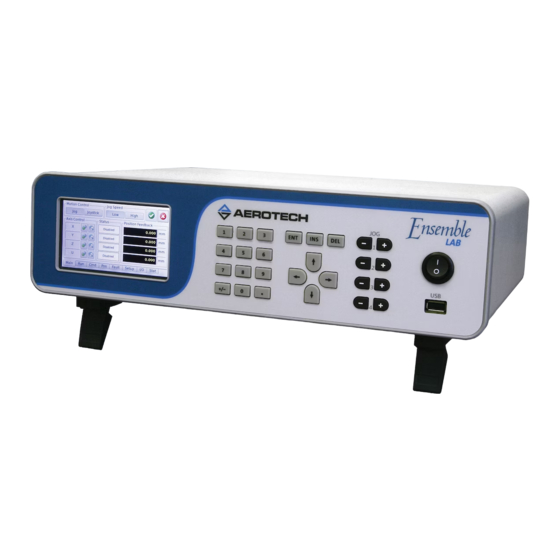
Introduction Chapter 1: Introduction Aerotech’s Ensemble LAB is a one to four axis desktop standalone motion controller with an integrated power supply. The Ensemble LAB is designed for applications where ease of operation is desired without sacrificing overall system capability. -
Page 14: Table 1-1: Ordering Options
Introduction Ensemble LAB Hardware Manual Table 1-1: Ordering Options Number of Axes (required) -2DS Configured for 2 axis DC brush/Stepper motor operation -3DS Configured for 3 axis DC brush/Stepper motor operation -4DS Configured for 4 axis DC brush/Stepper motor operation... - Page 15 Ensemble LAB Hardware Manual Introduction The following block diagram shows a connection summary (refer to Chapter 2 for more detailed connection information). Controller Amplifier Keypad Encoder +5V / Common LCD Touch PSO Output Display SIN, COS, MRK (RS422) 4 Opto Outputs...
-
Page 16: Electrical Specifications
Introduction Ensemble LAB Hardware Manual 1.1. Electrical Specifications The electrical specifications for the Ensemble LAB are listed below. Table 1-2: Electrical Specifications Description Ensemble LAB Power Input Voltage 100 VAC 115 VAC 200 VAC 230 VAC Supply Input Frequency 50-60 Hz... -
Page 17: System Power Requirements
Ensemble LAB Hardware Manual Introduction 1.1.1. System Power Requirements The following equations can be used to determine total system power requirements. The actual power required from the mains supply will be the combination of actual motor power (work), motor resistance losses, and efficiency losses in the power electronics or power transformer. -
Page 18: Mechanical Specifications
Introduction Ensemble LAB Hardware Manual 1.2. Mechanical Specifications The following figure shows the Ensemble LAB package dimensions. ETHERNET AUX I/O JOYSTICK ESTOP AXIS WARNING: HAZARDOUS VOLTAGE PRESENT UP TO J106 J105 10 MINUTES AFTER TB101 J104 J103 POWER IS DISCONNETED 95.6 [3.76]... -
Page 19: Environmental Specifications
Ensemble LAB Hardware Manual Introduction 1.3. Environmental Specifications Ambient Temperature Operating: 0° to 50°C (32° to 122° F) Storage: -30° to 85°C (-22° to 185° F) Humidity Maximum relative humidity is 80% for temperatures up to 31°C. Decreasing linearly to 50% relative humidity at 40°C. Non condensing. -
Page 20: Drive And Software Compatibility
Introduction Ensemble LAB Hardware Manual 1.4. Drive and Software Compatibility The following table lists the available drives and which version of the software first supported the drive. Drives that list a specific version number in the Last Software Version column will not be supported after the listed version. -
Page 21: Chapter 2: Installation And Configuration
Ensure that the antistatic material is not damaged during unpacking. D A N G E R : Cables should not be connected to or disconnected from the Ensemble LAB drive chassis while power is applied, nor should any drive modules be removed or inserted into it with power applied. -
Page 22: Electrical Installation
N O T E : The machine integrator, OEM or end user is responsible for meeting the final protective ground- ing requirements of the system. N O T E : Confirm that the AC power is the correct voltage before turning on power to the Ensemble LAB. Chapter 2... -
Page 23: Ac Power Connection
2.2.1. AC Power Connection AC input power to the Ensemble LAB is applied to the AC power receptacle that is located on the rear panel. The power cord connected to this receptacle also provides the protective earth ground connection and may serve as a Mains disconnect. -
Page 24: Io And Signal Wiring Requirements
Installation and Configuration Ensemble LAB Hardware Manual 2.2.2. IO and Signal Wiring Requirements The I/O, communication, and encoder feedback connections are typically very low power connections. In some applications, especially when there are significant wire distances, a larger wire size may be required to reduce the voltage drop that occurs along the wire. -
Page 25: Minimizing Conducted, Radiated, And System Noise
5. The Ensemble LAB is a component designed to be integrated with other electronics. EMC testing must be conducted on the final product configuration. 6. Ferrite beads or Aerotech’s FBF-1 or FBF-2 filter adapters, may be used on the motor leads to reduce the effects of amplifier EMI/RFI, produced by PWM (pulse width modulation) amplifiers. -
Page 26: Motor And Feedback Connections
Installation and Configuration Ensemble LAB Hardware Manual 2.3. Motor and Feedback Connections Each 25-pin, D-style connector has encoder, limits, and Hall inputs, a 5 V power supply, and motor connections. Table 2-4: Motor Power and Feedback Connector Pin# Description In/Out/Bi Connector... -
Page 27: Encoder Interface
Installation and Configuration 2.3.1. Encoder Interface The Ensemble LAB is equipped with standard and auxiliary encoder feedback channels. The standard encoder interface is accessible through the feedback connector. The standard interface is a line driver encoder that will accept an RS-422 differential line driver signal. If the drive had been purchased with the - MXU or -MXR option, the standard encoder interface has been configured to accept an analog encoder. -
Page 28: Rs-422 Line Driver Encoder (Standard)
Installation and Configuration Ensemble LAB Hardware Manual 2.3.1.1. RS-422 Line Driver Encoder (Standard) The standard encoder interface accepts an RS-422 differential quadrature line driver signal. Invalid or missing signals will cause a feedback fault when the axis is enabled. An analog encoder is used with the -MXU or -MXR option (refer to Section 2.3.1.2. -
Page 29: Analog Encoder Interface
Ensemble LAB Hardware Manual Installation and Configuration 2.3.1.2. Analog Encoder Interface If the -MXU or -MXR option has been purchased, the primary encoder channel will accept an analog encoder input signal. The multiplication (interpolation) factor is determined by the EncoderMultiplicationFactor axis parameter. - Page 30 Installation and Configuration Ensemble LAB Hardware Manual PIN-15 2.43K 33PF 10PF 220PF 4.7K PIN-13 2.43K AD8656 .0018 .0018 4.7K 33PF +2.4V REF 10UF 6.3V PIN-14 2.43K 33PF 10PF 220PF 4.7K PIN-2 2.43K AD8656 .0018 .0018 4.7K 33PF +2.4V REF 10UF 6.3V PIN-16 8.06K...
-
Page 31: Encoder Phasing
Ensemble LAB Hardware Manual Installation and Configuration 2.3.1.3. Encoder Phasing Incorrect encoder polarity will cause the system to fault when enabled or when a move command is issued. Figure 2-6 illustrates the proper encoder phasing for clockwise motor rotation (or positive forcer movement for linear motors). - Page 32 Installation and Configuration Ensemble LAB Hardware Manual Figure 2-7: Position Feedback in the Diagnostic Display Chapter 2 www.aerotech.com...
-
Page 33: Hall-Effect Interface
Ensemble LAB Hardware Manual Installation and Configuration 2.3.2. Hall-Effect Interface The Hall-effect switch inputs are recommended for AC brushless motor commutation but not absolutely required. The Hall-effect inputs accept 5-24 VDC level signals. Table 2-8: Hall-Effect Feedback Interface Pin Assignment... -
Page 34: Thermistor Interface
Installation and Configuration Ensemble LAB Hardware Manual 2.3.3. Thermistor Interface The thermistor input is used to detect an over temperature condition in a motor using a positive temperature coefficient sensor. As the temperature of the sensor increases, so does the resistance. Under normal operating conditions, the resistance of the thermistor is low (i.e., 100 ohms) which will result in a low input... -
Page 35: End Of Travel Limit Input Interface
Ensemble LAB Hardware Manual Installation and Configuration 2.3.4. End of Travel Limit Input Interface End of Travel (EOT) limits are required to define the end of the physical travel on linear axes. Positive or clockwise motion is stopped by the clockwise (CW) end of travel limit input. Negative or counterclockwise motion is stopped by the counterclockwise (CCW) end of travel limit input. -
Page 36: End Of Travel Limit Phasing
Installation and Configuration Ensemble LAB Hardware Manual 2.3.4.1. End of Travel Limit Phasing If the EOT limits are reversed, you will be able to move further into a limit but be unable to move out. To correct this, swap the connections to the CW and CCW inputs at the motor feedback connector. The logic level of the EOT limit inputs may be viewed in the diagnostic display. -
Page 37: Motor Output Interface
Ensemble LAB Hardware Manual Installation and Configuration 2.3.5. Motor Output Interface The Ensemble LAB is capable of driving three motor types: Brushless Motors: refer to Section 2.3.5.1. DC Brush Motors: refer to Section 2.3.5.2. Stepper Motors: refer to Section 2.3.5.3. Table 2-11:... -
Page 38: Brushless Motor Connections
A, B, and C Hall/motor lead sets and indicate the correct connections to the controller. N O T E : If using standard Aerotech motors and cables, motor and encoder connection adjustments are not required. Chapter 2... - Page 39 Ensemble LAB Hardware Manual Installation and Configuration Powered Motor Phasing Refer to the Motor Phasing Calculator in the Configuration Manager for motor, Hall, and encoder phasing. Feedback Monitoring The state of the encoder and Hall-effect device signals can be observed in the Motion Composer.
- Page 40 With the designations of the motor and Hall leads of a third party motor determined, the motor can now be connected to an Aerotech system. Connect motor lead A to motor connector A, motor lead B to motor connector B, and motor lead C to motor connector C. Hall leads should also be connected to their respective feedback connector pins (Hall A lead to the Hall A feedback pin, Hall B to Hall B, and Hall C to Hall C).
-
Page 41: Dc Brush Motor Connections
When the voltmeter indicates a positive value, the motor leads have been identified. 5. Connect the motor lead from the voltmeter to the ØA motor terminal on the Ensemble LAB. Connect the motor lead from the negative lead of the voltmeter to the ØC motor terminal on the Ensemble LAB. -
Page 42: Stepper Motor Connections
Figure 2-20: Clockwise Motor Rotation N O T E : If using standard Aerotech motors and cables, motor and encoder connection adjustments are not required. N O T E : After the motor has been phased, use the ReverseMotionDirection parameter to change the dir- ection of “positive”... -
Page 43: Emergency Stop Sense Input (Tb101)
Ensemble LAB Hardware Manual Installation and Configuration 2.4. Emergency Stop Sense Input (TB101) The ESTOP sense input is used to monitor the state of an external safety circuit only. This state is indicated by the software and may be used to facilitate system restart. This ESTOP sense input is not intended to be a complete safety system. -
Page 44: Auxiliary I/O Connector (J106)
Input (1) Software configured option (2) For PSO, see Section 2.5.2. Mating Connector Aerotech P/N Third Party P/N Connector ECK01259 Kycon K86-AA-26P Backshell ECK01022 Amphenol 17-1725-2 NOTE: These items are provided as a set under the Aerotech P/N: MCK-26HDD. Chapter 2 www.aerotech.com... -
Page 45: Auxiliary Encoder Channel
Ensemble LAB Hardware Manual Installation and Configuration 2.5.1. Auxiliary Encoder Channel The auxiliary encoder interface accepts an RS-422 differential quadrature line driver signal. Invalid or missing signals will cause a feedback fault when the axis is enabled. This encoder channel can be used as an input for master/slave operation (handwheel) or for dual feedback systems. - Page 46 Installation and Configuration Ensemble LAB Hardware Manual AUX SIN- J106-2 AUX SIN+ ADG801 J106-1 ADM1485 ENCODER FAULT DETECTION AUX COS- J106-11 AUX COS+ ADG801 J106-10 ADM1485 AUX MRK- J106-19 AUX MRK+ ADG801 J106-20 ADM1485 Figure 2-22: Auxiliary Encoder Channel Chapter 2...
-
Page 47: Position Synchronized Output (Pso)
Ensemble LAB Hardware Manual Installation and Configuration 2.5.2. Position Synchronized Output (PSO) The PSO can be programmed to generate an output synchronized to the feedback position and is typically used to fire a laser or sequence an external device. Trigger signals may be derived from a feedback channel or a software trigger. - Page 48 Installation and Configuration Ensemble LAB Hardware Manual Single Ended +5 VDC J106 Active Low Output Aux. Marker Active High Output 74AHCT1G125 Differential +5 VDC 120 - 180 Ω (typical) J106 Active Low Aux. Marker Output * Opto-Isolated +5 VDC Isolated Section J106 10 mA 180 Ω...
-
Page 49: Opto-Isolated Outputs
Ensemble LAB Hardware Manual Installation and Configuration 2.5.3. Opto-Isolated Outputs 0-3 The digital outputs are optically-isolated and may be connected in sourcing or sinking configurations. The digital outputs are designed to connect to other ground referenced circuits and are not intended to provide high-voltage isolation. - Page 50 Installation and Configuration Ensemble LAB Hardware Manual N O T E : Outputs must be connected as all sourcing or all sinking. J106 OPTOCOM J106-15 OPTOOUT0 J106-7 LOAD OPTOOUT1 J106-8 LOAD OPTOOUT2 J106-9 5-24 VDC OPTOOUT3 LOAD J106-16 OUTPUT SWITCHES...
-
Page 51: Opto-Isolated Inputs
Ensemble LAB Hardware Manual Installation and Configuration 2.5.4. Opto-Isolated Inputs 0-3 The digital inputs are opto-isolated and may be connected to current sourcing or current sinking devices, as shown in Figure 2-26 Figure 2-27. These inputs are designed to connect to other ground-referenced circuits and are not intended for high-voltage isolation. - Page 52 Installation and Configuration Ensemble LAB Hardware Manual N O T E : Inputs must be connected in the all sourcing or all sinking configuration. J106 INPUT SWITCHES OPTOIN0 J106-17 OPTOIN1 J106-18 OPTOIN2 J106-25 5-24VDC OPTOIN3 J106-26 OPTOINCOM J106-24 Figure 2-26:...
-
Page 53: High-Speed User Inputs
Ensemble LAB Hardware Manual Installation and Configuration 2.5.5. High-Speed User Inputs 4-5 The high speed inputs 4-5 are typically used as a sample signal for data collection. Table 2-23: High-Speed Input Specifications Specification Value Input Voltage 5V or 24 V Input Current... -
Page 54: Analog Output
Installation and Configuration Ensemble LAB Hardware Manual 2.5.6. Analog Output 0 The analog output is set to zero when power is first applied to the system or during a system reset. Table 2-25: Analog Output 0 Specifications Specification Value Output Voltage -10 V to +10 V... -
Page 55: Analog Input
Ensemble LAB Hardware Manual Installation and Configuration 2.5.7. Analog Input 0 To interface to a single-ended (non-differential) voltage source, connect the signal common of the source to the negative input and the analog source signal to the positive input. A floating signal source should be... -
Page 56: Joystick Interface (J105)
2.6. Joystick Interface (J105) Aerotech joysticks JI (NEMA12 (IP54) rated) and JBV are powered from 5V and have a nominal 2.5V output in the center detent position. Three buttons are used to select axis pairs and speed ranges. An optional interlock signal is used to indicate to the controller that the joystick is present. -
Page 57: Table 2-29: Joystick Connector Pin Assignment (J105)
Ensemble LAB Hardware Manual Installation and Configuration Table 2-29: Joystick Connector Pin Assignment (J105) Description In/Out/Bi Connector +5 Volt Power to joystick Output Button A (Axis Select) Input X Potentiometer [Analog Input 1] Input No Connection Reserved / No Connection... -
Page 58: Communication (Ethernet And Usb)
Method 1: Directly connect to the PC with a standard USB cable. The cable connector type must be Type A or Type B male depending on the PC, and Type B male on the Ensemble LAB. Method 2: Connect through a USB hub. The cable connector type must be Type A or Type B male depending on the hub, and Type B male on the Ensemble LAB. -
Page 59: Ethernet Interface
Aerotech recommends Method 2. Method 2 is a more typical configuration. The network can be a local network (the PC and Ensemble LAB are connected through a hub or switch) or remote (the devices are connected through a router). When connecting to a remote network, a crossover cable cannot be used;... -
Page 60: Pc Configuration And Operation Information
Installation and Configuration Ensemble LAB Hardware Manual 2.8. PC Configuration and Operation Information For additional information about PC configuration, hardware requirements, programming, utilities, and system operation refer to the Ensemble Help file. Chapter 2 www.aerotech.com... -
Page 61: Chapter 3: Maintenance
Cleaning The Ensemble LAB chassis can be wiped with a clean, dry, soft cloth. The cloth may be slightly moistened if required with water or isopropyl alcohol to aid in cleaning if necessary. In this case, be careful not to allow moisture to enter the Ensemble LAB or onto exposed connectors / components. - Page 62 Maintenance Ensemble LAB Hardware Manual This page intentionally left blank. Chapter 3 www.aerotech.com...
- Page 63 Aerotech makes no warranty that its products are fit for the use or purpose to which they may be put by the buyer, whether or not such use or purpose has been disclosed to Aerotech in specifications or drawings previously or subsequently provided, or whether or not Aerotech’s...
- Page 64 Aerotech's approval. On-site Warranty Repair If an Aerotech product cannot be made functional by telephone assistance or by sending and having the customer install replacement parts, and cannot be returned to the Aerotech service center for repair, and if Aerotech determines the problem could be warranty-related, then the following policy applies:...
- Page 65 Ensemble LAB Hardware Manual Revision History Appendix B: Revision History Rev # Description 1.02.00 The following sections have been updated: EU Declaration of Conformity Agency Approvals Section 2.2.2. IO and Signal Wiring Requirements Section 2.3. Motor and Feedback Connections Section 2.3.1.1. RS-422 Line Driver Encoder (Standard) Section 2.3.1.2.
- Page 66 Revision History Ensemble LAB Hardware Manual This page intentionally left blank. Appendix B www.aerotech.com...
- Page 67 Ensemble LAB Hardware Manual Index Index Emergency Stop Sense Input (TB101) Encoder Interface 2014/35/EU Encoder Phasing End of Travel Limit Input Interface AC Power Connection End of Travel Limit Phasing Altitude Environmental Specifications Ambient Temperature ESTOP Analog Encoder Interface Ethernet Interface...
- Page 68 Index Ensemble LAB Hardware Manual Minimum Load Resistance Stepper Motor Connections Mode of Operation Stepper Motor Phasing Motor and Feedback Connections Support Motor Connections 38,41-42 Motor Output Interface TB101 Motor Phasing 39,41-42 Technical Support Motor Phasing Oscilloscope Example Thermistor Interface...
Need help?
Do you have a question about the Ensemble LAB and is the answer not in the manual?
Questions and answers