Table of Contents
Advertisement
Quick Links
®
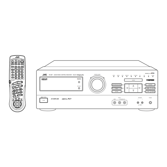
AUDIO/VIDEO CONTROL RECEIVER
!"#$%&'
RX-80PGD
RM-SR80U REMOTE CONTROL
TV
VCR
DVD
AUDIO
POWER
POWER
MULTI
POWER
VIDEO1 VIDEO2
VCR1
TAPE/VCR
TV
FM/AM
CD
PHONO
SOUND
DELAY
CNTR
DVD
MENU
1
2
3
CD
TEST
ENTER
REAR (L)
DISC
4
5
6
VCD
EFFECT
(REAR R)
DISC
7
8
9
RX-80P
AUDIO/VIDEO CONTROL RECEIVER
/P
VCR
SEA MODE
DAP MODE SURR MODE
CONTROL
10
0
+10
RETURN
FM MODE/MUTING
TV / VCR / TUNER
/ CD / DVD / VCD
SOUND
CONTROL
CONTROL
STANDBY
TAPE
VCR
MENU
MENU
EXIT
SET
POWER
MASTER VOLUME
VIDEO1
VIDEO2
ONE TOUCH
OPERATION
–
+
DAP/SURROUND MODE
DVD MULTI
DAP/SURROUND/DVD MULTI
ADJUST
SETTING
VIDEO 2
VIDEO
INSTRUCTIONS
!"
JAPAN
DESIGNED BY JVC
VCR1
TAPE/VCR
DVD
TV SOUND
FM
AM
CD
PHONO
SOURCE
SEA MODE
SEA
MEMORY
ADJUST
TUNER
MEMORY
SPEAKERS
PHONES
L
AUDIO
R
1
2
_ON —OFF
For Customer Use:
Enter below the Model No. and Serial
No. which are located either on the rear,
bottom or side of the cabinet. Retain this
information for future reference.
Model No.
Serial No.
LVT0101-001B
[UF]
Advertisement
Table of Contents

Related Manuals for JVC RX-80PGD


Summary of Contents for JVC RX-80PGD
- Page 1 DAP/SURROUND/DVD MULTI ADJUST SETTING VIDEO 2 SPEAKERS VIDEO AUDIO _ON —OFF !" JAPAN DESIGNED BY JVC PHONO SEA MODE MEMORY ADJUST TUNER MEMORY PHONES For Customer Use: Enter below the Model No. and Serial No. which are located either on the rear, bottom or side of the cabinet.
- Page 2 Warnings, Cautions and Others / Caution –– POWER switch! Disconnect the mains plug to shut the power off completely. The POWER switch in any position does not disconnect the mains line. The power can be remote controlled. CAUTION To reduce the risk of electrical shocks, fire, etc.: 1.
- Page 3 No obstructions, place on the level surface. In addition, maintain the best possible air circulation as illustrated. Wall or obstructions !"# !"#$%&' !"#$%&'()*+, !"#$%&' !"#$ %&'()*+,-./01 Spacing 15 cm or more RX-80PGD Floor !"#$%&'() !"#$%&'() !"#$%&'() !"#$%&'() !"#$%&' !( Front Stand height 15 cm or more...
-
Page 4: Table Of Contents
Using the On-Screen Display to Control the Receiver ... 37 COMPU LINK Remote Control System ... 41 AV COMPU LINK Remote Control System ... 42 Using the Remote Control for Operating JVC’s Audio/Video Components ... 44 Operating Other Manufactures’ TV ... 48 Troubleshooting ... 50 Specifications ... -
Page 5: Getting Started
Getting Started This section explains how to connect audio/video components and speakers to the receiver, and how to connect the power supply. Before Installation General • Be sure your hands are dry. • Turn the power off to all components. -
Page 6: Switches, Buttons And Controls
Switches, Buttons and Controls Become familiar with the main switches and controls on your receiver before use. RX-80P AUDIO/VIDEO CONTROL RECEIVER STANDBY POWER Refer to the pages in parentheses for details. Front Panel 1 Remote sensor (11) 2 Display (12) - Page 7 Remote Control RM-SR80U REMOTE CONTROL AUDIO POWER POWER MULTI POWER VIDEO1 VIDEO2 VCR1 TAPE/VCR FM/AM PHONO SOUND DELAY CNTR MENU TEST ENTER REAR (L) DISC EFFECT (REAR R) DISC SEA MODE DAP MODE SURR MODE CONTROL RETURN FM MODE/MUTING TV /VCR /TUNER / CD / DVD / VCD SOUND CONTROL...
-
Page 8: Connecting The Fm And Am Antennas
Connecting the FM and AM Antennas FM Antenna Connections ANTENNA (75 ) LOOP How to strip the 75 coaxial cable and connect it to the FM terminals 1. Strip back the outside covering of the 75 coaxial cable to expose the braided metallic mesh about 20 mm. 2. -
Page 9: Connecting The Speakers
R I G Notes: • To obtain the best possible output power from the receiver, and to prevent the receiver from • When you connect two pairs of the speakers to the FRONT SPEAKERS terminals, use the Right Speaker... - Page 10 Connecting the rear and center speakers Cut, twist and remove the insulation at the end of each speaker signal cable first, and then, connect rear speakers to the REAR SPEAKERS terminals and a center speaker to the CENTER SPEAKER terminals by using the cables.
-
Page 11: Connecting Audio/Video Components
To audio output If your audio components have a COMPU LINK-3 terminal The COMPU LINK remote control system allows you to control other JVC audio components from the receiver or vice versa. Connect your audio components and the receiver with the cable (monaural mini-plug supplied with those components) as well as the connection above. - Page 12 – If you use the AV COMPU LINK remote control system to operate the TV, connect the receiver to the Video Input 2 jack on the TV. – If you do not use the AV COMPU LINK remote control system to operate TV, connect the receiver to the Video Input 1 jack on the TV.
- Page 13 _ON —OFF If your video components have an AV COMPU LINK terminal The AV COMPU LINK remote control system allows you to control other JVC video components from the receiver or vice versa. For detailed information about the connection and the AV COMPU LINK remote control system, see page 42.
-
Page 14: Connecting The Power Cord
Connecting the Power Cord Before plugging the receiver into an AC outlet, make sure that all connections have been made. When the power cord is connected, the STANDBY lamp above the POWER button lights up. Keep the power cord away from the connecting cables for the TV, VCR, and antenna. The power cord may cause noise or screen interference. -
Page 15: Basic Operations
Basic Operations The following operations are commonly used when you play any sound source. TV / VCR / TUNER IMPORTANT / CD / DVD / VCD When using the Remote Control, check to see if its remote control mode selector is set to the “TV / VCR / TUNER / CD / DVD / VCD”... -
Page 16: Adjusting The Volume
FM/AM* TAPE/VCR* PHONO* Note: When you press one of the Source selecting buttons marked above with an asterisk (*), the receiver automatically turns on. Adjusting the Volume MASTER VOLUME When you change the volume level, the volume level is shown on the display. -
Page 17: Muting The Sound
Remote Control Recording a Source You can record any source playing through the receiver to the cassette deck (or VCR) connected to the TAPE/ VCR jacks and the VCR connected to the VCR1 jacks at the same time. While recording, you can listen to the selected sound source at whatever sound level you like, without affecting the sound levels of the recording. -
Page 18: Basic Settings
Basic Settings Some of the following settings are required after connecting and positioning your speakers in your listening room, while others will make operations easier. Adjusting the Front Speaker Output Balance If the sounds you hear from the front right and left speakers are unequal, you can adjust the speaker output balance. -
Page 19: Using The Sleep Timer
Using the Sleep Timer Using the Sleep Timer, you can fall asleep to music and know the receiver will turn off by itself rather than play all night. On the front panel only: 1. Press SETTING so that the Control % / fi / @ / # buttons work for setting the Sleep Timer SETTING The lamp next to the button lights up. -
Page 20: Selecting The Center Speaker Size
Selecting the Center Speaker Size You can register the information on the center speaker after all connections are completed. If you do this registration first, you do not have to adjust the center speaker mode when you want to activate the surround sound. -
Page 21: Using Visual Confirmation
Using Visual Confirmation When you operate the receiver, you can see what you are doing, by showing it on the TV screen. To use this function, you need to connect the TV to the MONITOR OUT jack on the rear panel (see page 9), and set the TV’s input mode to the proper position to which the receiver is connected. -
Page 22: One Touch Operation
About the One Touch Operation JVC’s One Touch Operation function is used to assign and store different sound settings for each different playing source. By using this function, you don’t have to change the settings every time you change the source. -
Page 23: Receiving Radio Broadcasts
Receiving Radio Broadcasts You can browse through all the stations or use the preset function to go immediately to a particular station. Tuning in Stations Manually On the front panel only: 1. Press TUNER so that the Control % / fi / @ / # buttons work for tuner settings. TUNER MEMORY The lamp next to the button lights up. -
Page 24: Using Preset Tuning
Storing a new station on a used number erases the previously stored one. CAUTION: Preset stations may be erased when power is cut off to the receiver, as when it is unplugged from the AC outlet or a power failure occurs. If the preset stations are lost, simply set the stations again. -
Page 25: Selecting The Fm Reception Mode
From the remote control: FM/AM 1. Press FM/AM. Each time you press the button, the band alternates between FM and AM. 2. Press 10 keys to select a preset channel number. DELAY CNTR • For channel number 5, press 5. MENU •... -
Page 26: Assigning Names To Preset Stations
Assigning Names to Preset Stations You can assign a name of up to five characters to each preset station (from preset channel number 1 to 20). When a preset station is tuned in, its assigned name will appear on the display. On the front panel only: 1. -
Page 27: Using The Sea Modes
Using the SEA Modes The SEA (Sound Effect Amplifier) modes give you control of the way your music sounds. Note: The SEA modes cannot be used for recording. Selecting Your Favorite SEA Mode On the front panel: 1. Press SEA MODE so that the Control % / fi buttons work for selecting the SEA mode. SEA MODE The lamp next to the button lights up. -
Page 28: Creating Your Own Sea Mode
Creating Your Own SEA Mode You can adjust and store your own SEA adjustment into memory (USERMODE). On the front panel only: If you do not want to store your adjustment, but rather want to adjust the SEA temporarily, skip step 3 below. 1. -
Page 29: Activating The Surround Sounds
Activating the Surround Sounds The receiver can reproduce the sounds of the DVD player with its the analog discrete output mode turned on. Moreover, the built-in digital surround processor provides two groups of programs — DAP (Digital Acoustic Processor) modes and surround modes (Dolby Surround and JVC Theater Surround). -
Page 30: Using The Dap Modes
Using the DAP Modes You can use five DAP modes — “Dance Club, Live Club, Hall, Pavilion, and Headphones.” These modes (except “Headphones”) require the front speakers and the rear speakers, but do not require a center speaker to enlarge the sound field. Among the DAP modes, “Headphones”... - Page 31 From the remote control: 1. Set the remote control mode selector to the “SOUND CONTROL” position. TV / VCR / TUNER / CD / DVD / VCD 10 keys are activated for adjusting the sounds. SOUND CONTROL 2. Press DAP MODE until the DAP mode you want appears on the display. The DAP indicator also lights up on the display.
-
Page 32: Using The Dvd Multi Playback Mode
Using the DVD MULTI Playback Mode This receiver provides the DVD MULTI playback mode for reproducing the analog discrete output mode of the DVD player. Before playing back a DVD, refer also to the manual supplied with the DVD player. - Page 33 5. Press Control @ / # to adjust the center speaker output level. • Pressing Control @ decreases the output level up to –10 dB. • Pressing Control # increases the output level up to +10 dB. 6. Press Control % / fi until “–REAR L+” appears on the display. 7.
-
Page 34: Using The Surround Modes
Using the Surround Modes With this receiver, you can use two types of the surround mode — Dolby Surround and JVC Theater Surround Speaker arrangements for surround mode The following illustrations show how to obtain the optimum sound environment for surround modes. Try to find the speaker direction and location to create the optimum sound field. - Page 35 Preparing for the surround mode Once you have set the surround modes, you can use the same adjustment every time you want to activate the surround you want. The receiver memorizes surround adjustments for each mode. Note: When you select “DVDMULTI” as the source to play, you cannot select or adjust the surround mode.
- Page 36 5. Press Control % / fi until “CNT MODE” (Center Mode) appears on the display. 6. Press Control @ / # to select the center mode. Each time you press the button, the center modes change as follows: WIDE: NORMAL: PHANTOM: OFF: Notes:...
- Page 37 The center tone cannot be adjusted when sounds do not come out of the center speaker. If you have selected the JVC Theater Surround, go to the following steps. 14. Press Control % / fi until “–EFFECT+” appears on the display.
- Page 38 6. Press TEST again to stop the test tone. TEST If you have selected the JVC Theater Surround, go to the following steps. 7. Press EFFECT to adjust the effect level. EFFECT Each time you press the button, the effect level changes as follows: Remote Control As the number increases, the surround mode becomes stronger.
- Page 39 Activating the surround modes Once you have set the surround modes, you can use the same adjustment every time you want to enjoy the surround you want. The receiver memorizes surround adjustments for each mode. Note: When you select “DVDMULTI” as the source to play, the surround mode is canceled temporarily.
-
Page 40: Using The On-Screen Display To Control The Receiver
To use this function, you need to connect the TV to the MONITOR OUT jack on the rear panel (see page 9), and set the TV’s input mode to the appropriate position to which the receiver is connected. When the TV’s input mode is for TV, you cannot see the on-screen display. - Page 41 Listening at Low Volume (Loudness) 1. Press MENU SET. The MAIN MENU appears on the TV. 2. Press % / fi to move to “SETTING,” then press @ / #. The SETTING menu appears. 3. Press % / fi to move to “LOUDNESS.”...
- Page 42 Operating the Tuner 1. Press MENU SET. The MAIN MENU appears on the TV. 2. Press % / fi to move to “TUNER,” then press @ / #. The TUNER menu appears. 3. Press % / fi to move to the item you want to set or adjust, then press @ / #. On the TUNER menu, you can do the following: “CH.”: Select a preset channel station.
- Page 43 “TEST”: Output a test tone. “CENTER”: Adjust the center speaker output level. “CENTER TONE”: Select the center tone. For JVC Theater Surround: “CENTER MODE”: Select the center mode. “TEST”: Output a test tone. “CENTER”: Adjust the center speaker output level.
-
Page 44: Compu Link Remote Control System
Automatic Source Selection When you press the play (3 3 3 3 3 ) button on a connected component or on its own remote control, the receiver automatically turns on and changes the source to the component. On the other hand, if you select a new source on the receiver or the remote control, the selected component begins playing immediately. -
Page 45: Av Compu Link Remote Control System
AV COMPU LINK Remote Control System The AV COMPU LINK remote control system allows you to operate JVC video components (TV, VCR, and DVD player) through the receiver. CONNECTIONS: To use this remote control system, you need to connect the video components you want to operate, following the procedures below. - Page 46 Automatic Selection of TV’s Input Mode • When you select “TV SOUND” as the source to play on the receiver, the TV automatically changes the input mode to the TV tuner so that you can watch TV. • When you select “VIDEO1,” “VIDEO2,” or “TAPE/VCR” as the source to play on the receiver, the TV automatically changes the input mode to the Video Input 2 so that you can watch the playback picture.
-
Page 47: Using The Remote Control For Operating Jvc's Audio/Video Components
Using the Remote Control for Operating JVC’s Audio/Video Components You can operate JVC’s audio and video components with this receiver’s remote control, since control signals for JVC components are preset in the remote control. Notes: • If you use the buttons on the front panel or the menu function to choose a source, the remote control will not operate that source. - Page 48 CD player RM-SR80U REMOTE CONTROL After pressing CD (with the remote control mode selector set to the “TV / VCR / TUNER / CD / DVD / VCD” AUDIO POWER POWER MULTI POWER position), you can perform the following operations on a CD player: VIDEO1 VIDEO2 VCR1 TAPE/VCR...
- Page 49 To operate JVC’s video components using this remote control: • Some JVC VCR can accept two types of the control signals — remote code “A” and “B.” Before using this remote control, make sure that the remote control code of the VCR connected to the VCR1 jacks is set to code “A.”...
- Page 50 Video CD player After pressing VCD DISC or VCD CONTROL (with the remote control mode selector set to the “TV / VCR / TUNER / CD / DVD / VCD” position) while playing back a Video CD player, you can perform the following operations: PLAY: ¢...
-
Page 51: Operating Other Manufactures' Tv
4. Follow the procedures on this page and the following page again. If you want to use the remote control to operate JVC’s components, you do not need to follow this step. To change the transmittable signals for operating another manufacturer’s TV 1. - Page 52 Manufacturers’ codes for TV Aiwa Beijing Changhong 05, 06, 16, 25 Daewoo Ferguson Finlux Funai Grundig Hitachi Jinxing Konka LG (Goldstar) Mitsubishi Mivar Noblex Nokia Panasonic Peijin Peony 23, 24, 25 Philips Samsung Sanyo Sharp Sony 16, 28 Thomson Toshiba Manufacturers’...
-
Page 53: Troubleshooting
Troubleshooting Use this chart to help you solve daily operational problems. If there is any problem you cannot solve, contact your JVC service center. PROBLEM The display does not light No sound from speakers. Sound from one speaker only. Continuous hiss or buzzing during FM reception. -
Page 54: Specifications
60 watts per channel, min. RMS, driven into 8 ohms at 1 kHz, with no more than 5 % total harmonic distortion. 0.02 %* at 90 watts output (* Measured by JVC Audio Analysis System) 2.5 mV/47 k ohms 230 mV/47 k ohms... - Page 55 FM tuner (IHF) Tuning Range Usable Sensitivity Monaural 50 dB Quieting Sensitivity Monaural Stereo Signal-to-Noise Ratio Monaural (IHF-A weighted) Stereo Total Harmonic Distortion Monaural Stereo Stereo Separation at REC OUT Capture Ratio Alternate Channel Selectivity Frequency Response AM tuner Tuning Range Usable Sensitivity Loop antenna External antenna...
- Page 56 ® VICTOR COMPANY OF JAPAN, LIMITED ® Registered Trademark owned and licensed by VICTOR COMPANY OF JAPAN, LTD. 1098OFMMDWJSC EN, CH...
Need help?
Do you have a question about the RX-80PGD and is the answer not in the manual?
Questions and answers