
Related Manuals for Culligan ClearLink PRO


Summary of Contents for Culligan ClearLink PRO
- Page 1 Cat. No. 01033136 Rev. D 05/19/21 DCO # 210095 ClearLink Wireless Filtration Control Models from 2021 Installation, Operation, and Service Instructions with Parts Lists © 2021 Culligan International Company...
- Page 2 We encourage Culligan users to learn about Culligan products, but we believe that product knowledge is best obtained by consulting with your Culligan dealer. Untrained individuals who use this manual assume the risk of any resulting property damage or personal injury.
-
Page 3: Table Of Contents
Introduction ................ Culligan Connect App Installation for Aquasential About this Manual ............® ClearLink™ PRO ............Safe Practices..............Culligan Connect App Installation for all other Serial Numbers ............... ClearLink™ products ............ ClearLink PRO .............. ™ Pairing to Smart Device ........... - Page 4 This page intentionally left blank. Culligan ClearLink Cat. No. 01033136 ®...
-
Page 5: Read This Manual First
Introduction Read this Manual First Before you operate the Culligan ClearLink systems, read this manual to become ® ™ familiar with the device and its capabilities. The Aquasential ClearLink PRO, ClearLink PRO, ClearLink Connect, and ® ™ ™ ™ Drinking Water Connect manifolds are certified by WQA against CSA B483.1, NSF/ ANSI 372 for low lead requirement, NSF/ANSI 42 and NSF/ANSI 58 for material safety and structural integrity. -
Page 6: About This Manual
This publication is based on information available when approved for printing. Continuing design refinement could cause changes that may not be included in this publication. NOTE Do not remove or destroy the serial number. It must be referenced on request for warranty repair or replacement. Culligan ClearLink Cat. No. 01033136 ®... -
Page 7: Clearlink ™ Pro
This Wi-Fi enabled ClearLink keeps all of the same functionality of the ClearLink PRO but adds the ability to connect to the Culligan Connect App. Track water consumption,... -
Page 8: Drinking Water Connect
Culligan Connect App. Track water consumption, contaminants being removed, filter / membrane life and if a leak is detected from anywhere, using the convenience of an app. -
Page 9: Aquasential ® Clearlink ™ Pro
RO drinking water system available. This version of the ClearLink allows you to keep the great features of the ClearLink PRO all while being integrated directly into your Smart RO system, giving you more information at your fingertips. Outlet to ClearLink PRO top side port Outlet to tank... -
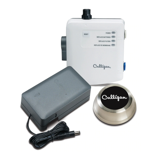
Page 10: Parts Included
Pressure Range: 30-120 psi (207-827 kPa) Temperature Range: 40-100º F (4.4 - 37.7º C) Precautions WARNING! Follow all precautions indicated in the manual provided with the Culligan water treatment system. WARNING! For systems using a booster or distribution pump, the pressure of the treated water cannot exceed the pressure of the cold water supply. -
Page 11: Setting Capacity And Tds Function (All Models)
Setting Capacity and TDS Function (All Models) NOTE This section does not apply to Aquasential ClearLink PRO Find the dip switches on the front of the circuit board. SW2 and SW3 set the time and capacity for the filter reminder. -
Page 12: Installation (All Models)
Disconnect the cold water line from the cold water shut-off valve. NOTE If rigid plumbing pipe (metal or plastic) is used, you may need to shorten the pipe using a hacksaw or pipe cutter to accommodate the control box. Culligan ClearLink Cat. No. 01033136 ®... - Page 13 Connect the control box to the cold water shut-off valve and the water line to the Faucet as shown. Culligan recommends 1/2 - 3/4 additional turns past finger-tight. CAUTION! The stationary hex nut on the outlet of the ClearLink should not be used to over-tighten the hose fitting.
- Page 14 WARNING! Install the air gap as high as possible using air gap installation bracket. WARNING! Failure to mount the air gap device vertically will cause it to leak water. Culligan ClearLink Cat. No. 01033136 ®...
- Page 15 Connect the drain line coming from the RO system to the 1/4” connection of the air gap device. NOTE Drain line adapters are available through Culligan Marketplace that can be used when considering the best drain line connection. Outlet to ClearLink top side port...
-
Page 16: External Flow Switch For A Secondary Outlet
External Flow Switch for a Secondary Outlet For use with ClearLink Connect and as an optional accessory on the Drinking Water Connect. Not available for use with ClearLink PRO or the Aquasential ClearLink PRO. "Routing Guides" on page NOTE External flow switch must be installed after the post filter. - Page 17 Flow Switch Wiring NOTE The standard length of the flow switch wire is 3’. If needed, a 40’ wire extension is available separately. 10. Reinsert screws. Remove Screws Remove the back cover. Push on orange tab, insert wire, then let go of orange tab.
-
Page 18: Flow Switch 40' Wire Extension Kit (If Applicable)
Insert wires into the connector on the PCB, see "Leak Sensor Installation". Leak Sensor Installation NOTE For use with ClearLink Connect and Drinking Water Connect. Not available for use with ClearLink PRO or the Aquasential ClearLink Pro. Plug in Leak Sensor Culligan ClearLink Cat. No. 01033136 ®... - Page 19 System Startup Confirm that the bypass valve is in the closed position (pointed down). NOTE When in the open position, the bypass valve simply allows incoming water to flow straight to the outlet without having to pass through the solenoid junction. When the bypass valve is open, it is possible for treated water to mix with the unfiltered water depending...
- Page 20 This should cause the leak sensor light on the control box (page 19) to flash, the unit to beep and the Culligan Connect App (if setup) to notify the user of the error. Dry pins and place at the lowest point in the cabinet or under the ClearLink Control Box.
- Page 21 Use the provided screw to hang the battery box on the side of the cabinet. Figure 6. Hang Battery Box on Side of Cabinet Install two AAA batteries (not included) into the remote button. 7a. Burp air after assembling battery cover. To relieve air, lift back one edge of the base, press center of rubber down, release edge.
-
Page 22: Button Display Guide
Filter Capacity Lights: Shows from 1-6 lights depending on filter capacity remaining, 6 lights => 80% and 1 light =<10%. Culligan Logo: Flashes when treated water is not available from the faucet. Stays solid while treated water is being dispensed from the faucet. - Page 23 Control Box Operation ClearLink™ Power: Flashes green at power up, filter capacity reset, and while dispensing filtered water. Continues to flash for 1 minute after the flow of filtered water has stopped. Replace Batteries: Flashes red when the batteries for the control box need to be replaced.
-
Page 24: Culligan Connect App Installation For Aquasential
Download and install “Culligan Connect” app from the Google Play Store to the customer’s smart device. Log in if the customer has an existing Culligan Connect app or create a new account if they do not. Verify through the email on the customer's tablet/phone. - Page 25 Select your local Wi-Fi network, enter Wi-Fi password (if applicable) and connect device. Using a paper clip, press and release the Wi-Fi Reset to complete setup (the Wi-Fi LED will begin flashing). 10. Your App and device will now pair. 11.
-
Page 26: Pair To Iphone Or Ipad
Pair to iPhone or iPad Go to Apple's App Store to download and install “Culligan Connect” app to the customer’s smart device. Go to device settings and connect to their local Wi-Fi network. Launch Culligan Connect App. Create a new account by selecting “Create an account”. -
Page 27: Viewing Device On C-Port
Viewing Device On C-Port To ensure you are able to monitor your device on C-Port you must enter your dealer number within the app. Select settings icon in upper Select “Settings” at bottom Select “Dealer” tab and enter corner of home screen. of the screen. -
Page 28: Best Practices For Installations
• If possible, use the optional 01029455 AC Adapter instead of batteries for the installation. Note that this adapter is only for use with the ClearLink PRO, ClearLink Connect and Drinking Water Connect. • Using name brand high-quality alkaline batteries can greatly extend battery life and product functionally. -
Page 29: Troubleshooting Guide
Leak Detected and 1 beep when the water is turned off. Blue (Bottom Window) Wi-Fi Enabled and Paired Power light on Aquasential ClearLink PRO No power to Aquasential Ensure Aquasential Smart RO unit is powered on control box is not on ClearLink PRO control box and rechargeable battery has sufficient charge. -
Page 30: Service
Service ClearLink PRO and ClearLink Connect Components Descriptions Out to Faucet Flow Switch: Check Valve • Magnet is pushed up when water is flowing and • Prevents untreated water from detected by reed switch. Shown in the up position. entering RO tank/filter pack. -
Page 31: Flow Path Diagrams
Flow Path Diagrams ClearLink PRO, Aquasential ClearLink PRO, and ClearLink Connect Unfiltered Water Out to Faucet Bypass Open Filtered Water Out to Faucet Out to Faucet Inlet from Cold Water Line From Solenoid closed, untreated water blocked from faucet Inlet from... - Page 32 Drinking Water Connect Out to RO Faucet Out to Faucet From RO To RO Inlet from Cold Water Line Culligan ClearLink Cat. No. 01033136 ®...
-
Page 33: Routing Guides
Routing Guides ClearLink Connect: Under Sink Install with Secondary Line Tank Flow Switch KITCHEN BASEMENT Cat. No. 01033136 Troubleshooting... - Page 34 ClearLink Connect: Remote Install with Secondary Line Plugged KITCHEN BASEMENT Flow Switch Wire To Drain Flow Switch Tank Culligan ClearLink Cat. No. 01033136 ®...
- Page 35 Drinking Water Connect: Under Sink Install with Secondary Line To Drain To Air Gap Tank KITCHEN BASEMENT Cat. No. 01033136 Troubleshooting...
- Page 36 Drinking Water Connect: Remote Install with Secondary Line KITCHEN BASEMENT To Drain Cap outlet or run to wash tub faucet or similar Tank Culligan ClearLink Cat. No. 01033136 ®...
-
Page 37: Installation Fittings And Replacement Parts List
D, E, F, G Leak Sensor** 01040530 — Aquasential Clearlink Pro Ext cable, 24' 01035431‡ — Solenoid Replacement Kit *Not shown **Not designed to work with ClearLink PRO ‡ Recommended Spare Parts Cat. No. 01033136 Installation Fittings and Replacement Parts List... - Page 38 Air Gap – Twin Inlet, 1/2"MIPT, 5/8" Barb Insert MS028703 Decorative Cap MS028704 Air Gap – Twin Inlet, No Fitting, No Cover MS028705 Drain Adapter Fitting – 3/8” Push-Connect MS028706 Drain Adapter Fitting – Universal, 3/8" Push-Connect Culligan ClearLink Cat. No. 01033136 ®...
-
Page 39: Two-Year Limited Warranty
2 full years from the original date of delivery. Culligan will replace any part which in Culligan’s opinion is defective, unless: (1) any part of the unit has been subjected to any type of tampering, alteration, or improper use after delivery, or (2) it has been repaired by anyone not approved by Culligan. -
Page 40: Index
Button Display Parts List Power Precautions Capacity ClearLink ClearLink Connect 7, 23, 34, 35 Remote Install 35, 37 ClearLink Pro Replace Batteries Components Replace Filters Control Box Replacement Parts List Control Box Lights Replace RO Membrane Control Box Operation Reset Button...
Need help?
Do you have a question about the ClearLink PRO and is the answer not in the manual?
Questions and answers
How much is a new clear link button, I was told that mine wasn't under warranty and it would be $500.00 for a new one