Culligan ClearLink Pro Installation And Operating Instructions Manual
Wireless filtration control, drinking water, agua potable
Hide thumbs
Also See for ClearLink Pro:
Table of Contents
Troubleshooting

Subscribe to Our Youtube Channel
Related Manuals for Culligan ClearLink Pro


Summary of Contents for Culligan ClearLink Pro
- Page 1 DRINKING WATER | AGUA POTABLE ClearLink Pro ™ Wireless Filtration Control Installation and operating instructions ClearLink Pro ™ Control de Filtración de Agua Inalámbrico Instrucciones de instalación y operación...
-
Page 2: Tools And Materials Required
40 –100°F (4.4 – 37.7°C) PRECAUTIONS WARNING: Follow all precautions indicated in the manual provided with the Culligan water treatment system. WARNING: For systems using a booster or distribution pump, the pressure of the treated water cannot exceed the pressure of the cold water supply. -
Page 3: Parts Included
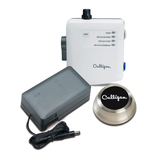
UNIVERSAL WIRELESS FILTRATION CONTROL PARTS INCLUDED: Remote Button Button Part No.: 01029450 Trim Ring Part Nos.: Chrome 01029452 Brushed Nickel 01029453 Oil Rubbed Bronze 01029454 Control Box Part No.: 01029449 Battery Box Part No.: 01029451 Tube Adapter 3/8" x 1/4" Mounting Screws Air Gap... -
Page 4: Installation
SET TING CAPACITY AND TDS FUNCTION NOTE: Set capacity and TDS function before starting installation. NOTE: To access the dip switches for setting capacity and TDS function, open the control box by removing the three screws in the rear cover. Find the dip switches on the front of the circuit board. - Page 5 Tighten the control box to the cold water shut-off Connect the inlet on the RO/Filter system to the > valve as shown. Tighten the lower end of cold water port marked "RO/Filter ." Wet the end of the line onto the top of the control box. plastic tubing with water and push it into the quick connect fitting adapter approximately 5/8˝...
- Page 6 RO AIR GAP INSTALLATION NOTE: These steps are only for RO installations using an air gap. NOTE: If your filtration system is not an RO, skip to System Startup on Page NOTE: Install the drain connection to the drain plumbing according to the manual provided with your RO system.
-
Page 7: System Start-Up
SYSTEM STARTUP Turn on the cold water supply and check for leaks. Confirm that the bypass valve is in the closed position (pointed down). If it leaks, refer to troubleshooting. Install four C batteries (not included) into the Use the provided screw to hang the battery box on battery box and plug into the jack on the bottom the side of the cabinet. - Page 8 SYSTEM STARTUP Turn on the faucet to full cold and push the button to activate the system. NOTE: The blue capacity lights should appear if the button and control box are communicating. NOTE: The button can be turned off with a second push or by turning off the faucet.
-
Page 9: Control Box Operation
Filter Capacity Lights: Shows from 1-6 lights depending on filter capacity remaining, 6 lights = >80% and 1 light = <10%. Culligan Logo: Flashes when treated water is not available from the faucet. Stays solid while treated water is being dispensed from the faucet. - Page 10 The bypass valve can be used to allow unfiltered water flow to the faucet while the issue is being corrected. THE CLEARLINK PRO IS CERTIFIED BY WQA AGAINST CSA B483.1, NSF/ANSI 372 FOR LOW LEAD REQUIREMENT, NSF/ANSI 42 AND NSF/ANSI 58 FOR MATERIAL SAFETY AND STRUCTURAL...
-
Page 11: One-Year Limited Warranty
1 full year from the original date of delivery. Culligan will replace any part which in Culligan’s opinion is defective, unless: (1) any part of the unit has been subjected to any type of tampering, alteration, or improper use after delivery, or (2) it has been repaired by anyone not approved by Culligan. -
Page 12: Herramientas Ymateriales Requeridos
PRECAUCIONES ADVERTENCIA: Siga todas las precauciones indicadas en el manual provisto con el sistema de tratamiento de agua de Culligan. ADVERTENCIA: Para sistemas empleando una bomba de refuerzo o de distribución, la presión del agua no tratado no puede exceder la presión del agua fría del suministro. -
Page 13: Piezas Incluidas
CONTROL DE FILTRACIÓN INALÁMBRICO UNIVERSAL PIEZAS INCLUIDAS: Botón del Control Remoto Botón Núm.: 01029450 Opciones de Anillo de Borde: Cromo 01029452 Níquel Cepillado 01029453 Bronce de Aceite Frotado 01029454 Caja de Control Parte Núm.: 01029449 Caja de Batería Parte Núm.: 01029451 Adaptadore de Tubo 3/8"... -
Page 14: Instalación
PROGRAMAR LA CAPACIDAD Y LA FUNCIÓN TDS NOTA: Favor de programar la capacidad y la función TDS antes de comenzar la instalación. NOTA: Para obtener acceso a los interruptores DIP para la capacidad y la función TDS, abra la caja de control por medio de retirar los tres tornillos de la cubierta trasera. Localice los interruptores DIP en la parte frontal de la placa de circuito. - Page 15 Aprieta la caja de control a la válvula de cierre de Conecte la entrada del sistema de filtración al agua fría según la diagrama. Aprieta la parte inferior puerto titulado "RO/Filter>" de la caja de control. de la línea de agua fría a la parte superior de la Moje el extremo del tubo de plástico con agua caja de control.
- Page 16 INSTALACIÓN DE ENTREHIERRO PARA OSMOSIS INVERSO NOTA: Los siguientes pasos aplican únicamente a instalaciones de osmosis inverso empleando un entrehierro. NOTA: Si su sistema de filtración no es de osmosis inverso, brinque a la sección de Inicio del Sistema en la página NOTA: Instale el conectador de drenaje al drenaje de acuerdo con el manual provisto con sú...
-
Page 17: Inicio Del Sistema
INICIO DEL SISTEMA Asegúrese que la válvula de derivación esté en la Abra el suministro de agua fría para averiguar posición cerrada (apuntada hacia abajo). si se derrama agua o no. Si el sistema está derramando agua, consulte la sección de Solución de Problemas. - Page 18 INICIO DEL SISTEMA Abra el grifo de agua fría completamente y empuja el botón para activar el sistema. NOTA: La luces azules de capacidad deben encenderse si el botón y la caja de control están comunicándose. NOTA: El botón se puede apagar con un Instale dos baterías AAA (no incluidas) en el botón segundo empujón o apagando el grifo.
- Page 19 6 luces = >80% y 1 luz = <10%. Logo Culligan: Enciende cuando agua filtrada no esté disponible desde el grifo. Permanece encendido mientras agua filtrada corra desde el grifo.
-
Page 20: Solución De Problemas
LAS CLEARLINK PRO HA SIDO CERTIFICADOS POR LA WQA SEGÚN LAS NORMAS CSA B483.1, NSF/ ANSI 372 PARA EL REQUISITO DE PLOMO BAJO, NSF/ANSI 42 Y NSF/ANSI 58 PARA LA SEGURIDAD... -
Page 21: Garantía Limitada De Un Año
La garantía se aplica al botón y la caja de batería. La garantía cubre los defectos en el material y la fabricación por un año completo desde la fecha original de entrega. Culligan reemplazará cualquier pieza que se considere defectuosa, con las siguientes excepciones: (1) si algún componente de la unidad estuvo sujeto a algún tipo de manipulación, alteración o uso inapropiado después de la... - Page 22 Culligan International Company Rosemont, Illinois 60018 www.culligan.com 847-430-2800 ©2015 Culligan International Company 01029457 B...
- Page 23 DRINKING WATER | AGUA POTABLE ClearLink Pro ™ Wireless Filtration Control Installation and operating instructions ClearLink Pro ™ Control de Filtración de Agua Inalámbrico Instrucciones de instalación y operación...
-
Page 24: Tools And Materials Required
40 –100°F (4.4 – 37.7°C) PRECAUTIONS WARNING: Follow all precautions indicated in the manual provided with the Culligan water treatment system. WARNING: For systems using a booster or distribution pump, the pressure of the treated water cannot exceed the pressure of the cold water supply. -
Page 25: Parts Included
UNIVERSAL WIRELESS FILTRATION CONTROL PARTS INCLUDED: Remote Button Button Part No.: 01029450 Trim Ring Part Nos.: Chrome 01029452 Brushed Nickel 01029453 Oil Rubbed Bronze 01029454 Control Box Part No.: 01029449 Battery Box Part No.: 01029451 Tube Adapter 3/8" x 1/4" Mounting Screws Air Gap... -
Page 26: Installation
SET TING CAPACITY AND TDS FUNCTION NOTE: Set capacity and TDS function before starting installation. NOTE: To access the dip switches for setting capacity and TDS function, open the control box by removing the three screws in the rear cover. Find the dip switches on the front of the circuit board. - Page 27 Tighten the control box to the cold water shut-off Connect the inlet on the RO/Filter system to the > valve as shown. Tighten the lower end of cold water port marked "RO/Filter ." Wet the end of the line onto the top of the control box. plastic tubing with water and push it into the quick connect fitting adapter approximately 5/8˝...
- Page 28 RO AIR GAP INSTALLATION NOTE: These steps are only for RO installations using an air gap. NOTE: If your filtration system is not an RO, skip to System Startup on Page NOTE: Install the drain connection to the drain plumbing according to the manual provided with your RO system.
-
Page 29: System Start-Up
SYSTEM STARTUP Turn on the cold water supply and check for leaks. Confirm that the bypass valve is in the closed position (pointed down). If it leaks, refer to troubleshooting. Install four C batteries (not included) into the Use the provided screw to hang the battery box on battery box and plug into the jack on the bottom the side of the cabinet. - Page 30 SYSTEM STARTUP Turn on the faucet to full cold and push the button to activate the system. NOTE: The blue capacity lights should appear if the button and control box are communicating. NOTE: The button can be turned off with a second push or by turning off the faucet.
-
Page 31: Control Box Operation
Filter Capacity Lights: Shows from 1-6 lights depending on filter capacity remaining, 6 lights = >80% and 1 light = <10%. Culligan Logo: Flashes when treated water is not available from the faucet. Stays solid while treated water is being dispensed from the faucet. -
Page 32: Troubleshooting
TROUBLESHOOTING LEAKS AT FILTER/RO INLET OR OUTLET CONNECTION: A rolled o-ring can block the tube from fully inserting. Use small screw driver to re-seat the o-ring and then confirm that the end of the tubing has a clean, square cut. LOW FILTERED WATER FLOW/SYSTEM RETURNS TO UNFILTERED FLOW AUTOMATICALLY: Low flow rates may not activate the control box electronics. -
Page 33: One-Year Limited Warranty
1 full year from the original date of delivery. Culligan will replace any part which in Culligan’s opinion is defective, unless: (1) any part of the unit has been subjected to any type of tampering, alteration, or improper use after delivery, or (2) it has been repaired by anyone not approved by Culligan. -
Page 34: Herramientas Ymateriales Requeridos
PRECAUCIONES ADVERTENCIA: Siga todas las precauciones indicadas en el manual provisto con el sistema de tratamiento de agua de Culligan. ADVERTENCIA: Para sistemas empleando una bomba de refuerzo o de distribución, la presión del agua no tratado no puede exceder la presión del agua fría del suministro. -
Page 35: Piezas Incluidas
CONTROL DE FILTRACIÓN INALÁMBRICO UNIVERSAL PIEZAS INCLUIDAS: Botón del Control Remoto Botón Núm.: 01029450 Opciones de Anillo de Borde: Cromo 01029452 Níquel Cepillado 01029453 Bronce de Aceite Frotado 01029454 Caja de Control Parte Núm.: 01029449 Caja de Batería Parte Núm.: 01029451 Adaptadore de Tubo 3/8"... -
Page 36: Instalación
PROGRAMAR LA CAPACIDAD Y LA FUNCIÓN TDS NOTA: Favor de programar la capacidad y la función TDS antes de comenzar la instalación. NOTA: Para obtener acceso a los interruptores DIP para la capacidad y la función TDS, abra la caja de control por medio de retirar los tres tornillos de la cubierta trasera. Localice los interruptores DIP en la parte frontal de la placa de circuito. - Page 37 Aprieta la caja de control a la válvula de cierre de Conecte la entrada del sistema de filtración al agua fría según la diagrama. Aprieta la parte inferior puerto titulado "RO/Filter>" de la caja de control. de la línea de agua fría a la parte superior de la Moje el extremo del tubo de plástico con agua caja de control.
- Page 38 INSTALACIÓN DE ENTREHIERRO PARA OSMOSIS INVERSO NOTA: Los siguientes pasos aplican únicamente a instalaciones de osmosis inverso empleando un entrehierro. NOTA: Si su sistema de filtración no es de osmosis inverso, brinque a la sección de Inicio del Sistema en la página NOTA: Instale el conectador de drenaje al drenaje de acuerdo con el manual provisto con sú...
-
Page 39: Inicio Del Sistema
INICIO DEL SISTEMA Asegúrese que la válvula de derivación esté en la Abra el suministro de agua fría para averiguar posición cerrada (apuntada hacia abajo). si se derrama agua o no. Si el sistema está derramando agua, consulte la sección de Solución de Problemas. - Page 40 INICIO DEL SISTEMA Abra el grifo de agua fría completamente y empuja el botón para activar el sistema. NOTA: La luces azules de capacidad deben encenderse si el botón y la caja de control están comunicándose. NOTA: El botón se puede apagar con un Instale dos baterías AAA (no incluidas) en el botón segundo empujón o apagando el grifo.
- Page 41 6 luces = >80% y 1 luz = <10%. Logo Culligan: Enciende cuando agua filtrada no esté disponible desde el grifo. Permanece encendido mientras agua filtrada corra desde el grifo.
-
Page 42: Solución De Problemas
SOLUCIÓN DE PROBLEMAS FUGAS DE AGUA POR ENTRADA O SALIDA DEL FILTRO/SISTEMA DE OSMOSIS INVERSO: Una arendala doblada podría estorbar en entrada completa del tubo. Use un destornillador pequeño para asentar la arendala de nuevo, y entonces asegurarse de que el extremo del tubo tenga una cortada cuadrada, y limpia. -
Page 43: Garantía Limitada De Un Año
La garantía se aplica al botón y la caja de batería. La garantía cubre los defectos en el material y la fabricación por un año completo desde la fecha original de entrega. Culligan reemplazará cualquier pieza que se considere defectuosa, con las siguientes excepciones: (1) si algún componente de la unidad estuvo sujeto a algún tipo de manipulación, alteración o uso inapropiado después de la... - Page 44 Culligan International Company Rosemont, Illinois 60018 www.culligan.com ©2015 Culligan International Company 01029457 A...
- Page 45 DRINKING WATER | AGUA POTABLE ClearLink ™ Wireless Filtration Control Installation and operating instructions Model US-CL ClearLink ™ Control de Filtración de Agua Inalámbrico Instrucciones de instalación y operación Modelo US-CL...
-
Page 46: Tools And Materials Required
English PARTS TOOLS & MATERIALS REQUIRED INCLUDED: • C Batteries x • Remote Button • AAA Batteries x • Control Box • Screwdriver • Battery Box • Adjustable Wrench • Tube Adapters 3/8" x 1/4" • Towels • Mounting Screws •... -
Page 47: Parts Included
UNIVERSAL WIRELESS FILTRATION CONTROL PARTS INCLUDED: Remote Button Control Box Battery Box Tube Adpaters 3/8" x 1/4" Mounting Screws Air Gap... -
Page 48: Installation
INSTALLATION NOTE: Refer to the manual provided with your filter/RO for installation instructions specific to that system. NOTE: Some installations may require adapters and fittings not included with the product. Review the manual and your installation before beginning. NOTE: Consult your local plumbing codes and install accordingly. Turn off cold water shut-off valve then turn on Disconnect the cold water line from the cold water the kitchen faucet and allow all water to drain... - Page 49 Tighten the control box to the cold water shut-off Connect the inlet on the RO/Filter system to the > valve as shown. Tighten the lower end of cold water blue port marked "RO/Filter ." Wet the end of line onto the top of the control box. the plastic tubing with water and push it into the quick connect fitting adapter approximately 5/8˝...
- Page 50 RO AIR GAP INSTALLATION NOTE: These steps are only for RO installations using an air gap. NOTE: Not all systems require an air gap. Only systems using a drain connection require the use of an air gap. NOTE: If your filtration system does not have a drain connection, skip to System Startup on Page NOTE: Install the drain connection to the drain plumbing according to the manual provided with your RO system.
-
Page 51: System Start-Up
SYSTEM STARTUP Confirm that the bypass valve is in the closed Turn on the cold water supply and check for leaks. position (pointed down). If it leaks, refer to troubleshooting. Install four C batteries (not included) into the Use the provided screw to hang the battery box on battery box and plug into the jack on the bottom the side of the cabinet. - Page 52 SYSTEM STARTUP Turn on the faucet to full cold and push the button to activate the system. NOTE: The blue capacity lights should appear if the button and control box are communicating. NOTE: The button can be turned off with a second push or by turning off the faucet.
-
Page 53: Control Box Operation
Filter Capacity Lights: Shows from 1-6 lights depending on filter capacity remaining, 6 lights = >80% and 1 light = <10%. Culligan Logo: Flashes when treated water is not available from the faucet. Stays solid while treated water is being dispensed from the faucet. -
Page 54: Troubleshooting
Call technical support at 1-800-721-7360. PRODUCT REGISTRATION Please be sure to go online within 30 days of purchase and register your product at www.register.culligan.com. Model: CulRF-M used in devices ClearLink PB, ClearLink RI and ClearLink R Contains the FCC ID: V7U-010291CL and IC: 6510B-010291CL This device complies with Industry Canada licence-exempt RSS standard(s). -
Page 55: One-Year Limited Warranty
1 full year from the original date of delivery. Culligan will replace any part which in Culligan’s opinion is defective, unless: (1) any part of the unit has been subjected to any type of tampering, alteration, or improper use after delivery, or (2) it has been repaired by anyone not approved by Culligan. -
Page 56: Herramientas Ymateriales Requeridos
PRECAUCIONES ADVERTENCIA: Siga todas las precauciones indicadas en el manual provisto con el sistema de tratamiento de agua de Culligan. ADVERTENCIA: Para sistemas empleando una bomba amplificador o de distribución, la presión del agua no tratado no puede exceder la presión del agua fría del suministro. -
Page 57: Piezas Incluidas
CONTROL DE FILTRACIÓN INALÁMBRICO UNIVERSAL PIEZAS INCLUIDAS: Botón del Control Remoto Caja de Control Caja de Batería Adaptadores de Tubo 3/8" x 1/4" Tornillos de Montaje Entrehierro... -
Page 58: Instalación
INSTALACIÓN NOTA: Favor de referirse al manual provisto con su filtro/sistema de osmosis inverso para las instrucciones de instalación especificadas para sú sistema de filtración. NOTA: Algunas instalaciones exigen adaptadores u otras piezas no incluidas con este producto. Repase el manual y el proceso de instalación antes de comenzar. NOTA: Consulte y instale de acuerdo con los códigos de plomería locales. - Page 59 Aprieta la caja de control a la válvula de cierre de Conecte la entrada del sistema de filtración al agua fría según la diagrama. Aprieta la parte inferior puerto azul titulado "RO/Filter>" de la caja de de la línea de agua fría a la parte superior de la control.
- Page 60 INSTALACIÓN DE ENTREHIERRO PARA OSMOSIS INVERSO NOTA: Los siguientes pasos aplican únicamente a instalaciones de osmosis inverso empleando un entrehierro. NOTA: No se exige un entrehierro con todos los sistemas. Sólamente los sistemas usando una conexión de drenaje necesitan el uso de un entrehierro. NOTA: Si su sistema de filtración no es de osmosis inverso, brinque a la sección de Inicio del Sistema en la página NOTA: Instale el conectador de drenaje al drenaje de acuerdo con el manual provisto...
-
Page 61: Inicio Del Sistema
INICIO DEL SISTEMA Asegúrese que la válvula de derivación esté en la Abra el suministro de agua fría para averiguar posición cerrada (apuntada hacia abajo). si se derrama agua o no. Si el sistema está derramando agua, consulte la sección de Solución de Problemas. - Page 62 INICIO DEL SISTEMA Abra el grifo de agua fría completamente y empuja el botón para activar el sistema. NOTA: La luces azules de capacidad deben encenderse si el botón y la caja de control están comunicándose. NOTA: El botón se puede apagar con un Instale dos baterías AAA (no incluidas) en el botón segundo empujón o apagando el grifo.
- Page 63 6 luces = >80% y 1 luz = <10%. Logo Culligan: Enciende cuando agua filtrada no esté disponible desde el grifo. Permanece encendido mientras agua filtrada corra desde el grifo.
-
Page 64: Solución De Problemas
REGISTRO DE PRODUCTO Asegúrese de registrar la compra de su producto en línea dentro de los 30 días a partir de la compra en www.register.culligan.com. LAS US-CL HA SIDO CERTIFICADOS POR LA WQA SEGÚN LAS NORMAS CSA B483.1, NSF/ANSI 372... -
Page 65: Garantía Limitada De Un Año
(2) si había sido reparado por una agencia no aprobada por Culligan. Culligan no asume responsabilidad alguna por los daños durante el transporte, y en caso de algún reclamo debido a dichos daños, el cliente deberá... - Page 66 Culligan International Company Rosemont, Illinois 60018 www.culligan.com Technical Support M–F 8:00AM–4:30PM (CST) Ayuda Técnica disponible de lunes a viernes, de 8:00 A.M. a 4:30 P.M. (CST) 1-800-721-7360 ©2015 Culligan International Company 01029484 B...
- Page 67 DRINKING WATER | AGUA POTABLE ClearLink ™ Wireless Filtration Control Installation and operating instructions Model US-CL ClearLink ™ Control de Filtración de Agua Inalámbrico Instrucciones de instalación y operación Modelo US-CL...
- Page 68 English PARTS TOOLS & MATERIALS REQUIRED INCLUDED: • C Batteries x • Remote Button • AAA Batteries x • Control Box • Screwdriver • Battery Box • Adjustable Wrench • Tube Adapters 3/8" x 1/4" • Towels • Mounting Screws •...
- Page 69 UNIVERSAL WIRELESS FILTRATION CONTROL PARTS INCLUDED: Remote Button Control Box Battery Box Tube Adpaters 3/8" x 1/4" Mounting Screws Air Gap...
- Page 70 INSTALLATION NOTE: Refer to the manual provided with your filter/RO for installation instructions specific to that system. NOTE: Some installations may require adapters and fittings not included with the product. Review the manual and your installation before beginning. NOTE: Consult your local plumbing codes and install accordingly. Turn off cold water shut-off valve then turn on Disconnect the cold water line from the cold water the kitchen faucet and allow all water to drain...
- Page 71 Tighten the control box to the cold water shut-off Connect the inlet on the RO/Filter system to the > valve as shown. Tighten the lower end of cold water blue port marked "RO/Filter ." Wet the end of line onto the top of the control box. the plastic tubing with water and push it into the quick connect fitting adapter approximately 5/8˝...
- Page 72 RO AIR GAP INSTALLATION NOTE: These steps are only for RO installations using an air gap. NOTE: Not all systems require an air gap. Only systems using a drain connection require the use of an air gap. NOTE: If your filtration system does not have a drain connection, skip to System Startup on Page NOTE: Install the drain connection to the drain plumbing according to the manual provided with your RO system.
-
Page 73: System Start-Up
SYSTEM STARTUP Confirm that the bypass valve is in the closed Turn on the cold water supply and check for leaks. position (pointed down). If it leaks, refer to troubleshooting. Install four C batteries (not included) into the Use the provided screw to hang the battery box on battery box and plug into the jack on the bottom the side of the cabinet. - Page 74 SYSTEM STARTUP Turn on the faucet to full cold and push the button to activate the system. NOTE: The blue capacity lights should appear if the button and control box are communicating. NOTE: The button can be turned off with a second push or by turning off the faucet.
- Page 75 Filter Capacity Lights: Shows from 1-6 lights depending on filter capacity remaining, 6 lights = >80% and 1 light = <10%. Culligan Logo: Flashes when treated water is not available from the faucet. Stays solid while treated water is being dispensed from the faucet.
- Page 76 Call technical support at 1-800-721-7360. PRODUCT REGISTRATION Please be sure to go online within 30 days of purchase and register your product at www.register.culligan.com. Model: CulRF-M used in devices ClearLink PB, ClearLink RI and ClearLink R Contains the FCC ID: V7U-010291CL and IC: 6510B-010291CL This device complies with Industry Canada licence-exempt RSS standard(s).
- Page 77 1 full year from the original date of delivery. Culligan will replace any part which in Culligan’s opinion is defective, unless: (1) any part of the unit has been subjected to any type of tampering, alteration, or improper use after delivery, or (2) it has been repaired by anyone not approved by Culligan.
- Page 78 PRECAUCIONES ADVERTENCIA: Siga todas las precauciones indicadas en el manual provisto con el sistema de tratamiento de agua de Culligan. ADVERTENCIA: Para sistemas empleando una bomba amplificador o de distribución, la presión del agua no tratado no puede exceder la presión del agua fría del suministro.
- Page 79 CONTROL DE FILTRACIÓN INALÁMBRICO UNIVERSAL PIEZAS INCLUIDAS: Botón del Control Remoto Caja de Control Caja de Batería Adaptadores de Tubo 3/8" x 1/4" Tornillos de Montaje Entrehierro...
- Page 80 INSTALACIÓN NOTA: Favor de referirse al manual provisto con su filtro/sistema de osmosis inverso para las instrucciones de instalación especificadas para sú sistema de filtración. NOTA: Algunas instalaciones exigen adaptadores u otras piezas no incluidas con este producto. Repase el manual y el proceso de instalación antes de comenzar. NOTA: Consulte y instale de acuerdo con los códigos de plomería locales.
- Page 81 Aprieta la caja de control a la válvula de cierre de Conecte la entrada del sistema de filtración al agua fría según la diagrama. Aprieta la parte inferior puerto azul titulado "RO/Filter>" de la caja de de la línea de agua fría a la parte superior de la control.
- Page 82 INSTALACIÓN DE ENTREHIERRO PARA OSMOSIS INVERSO NOTA: Los siguientes pasos aplican únicamente a instalaciones de osmosis inverso empleando un entrehierro. NOTA: No se exige un entrehierro con todos los sistemas. Sólamente los sistemas usando una conexión de drenaje necesitan el uso de un entrehierro. NOTA: Si su sistema de filtración no es de osmosis inverso, brinque a la sección de Inicio del Sistema en la página NOTA: Instale el conectador de drenaje al drenaje de acuerdo con el manual provisto...
-
Page 83: Inicio Del Sistema
INICIO DEL SISTEMA Asegúrese que la válvula de derivación esté en la Abra el suministro de agua fría para averiguar posición cerrada (apuntada hacia abajo). si se derrama agua o no. Si el sistema está derramando agua, consulte la sección de Solución de Problemas. - Page 84 INICIO DEL SISTEMA Abra el grifo de agua fría completamente y empuja el botón para activar el sistema. NOTA: La luces azules de capacidad deben encenderse si el botón y la caja de control están comunicándose. NOTA: El botón se puede apagar con un Instale dos baterías AAA (no incluidas) en el botón segundo empujón o apagando el grifo.
- Page 85 6 luces = >80% y 1 luz = <10%. Logo Culligan: Enciende cuando agua filtrada no esté disponible desde el grifo. Permanece encendido mientras agua filtrada corra desde el grifo.
- Page 86 Si las fugas de agua persisten, o si hay otras fugas de agua de la caja de control, favor de apagar el suministro de agua. Sírvase llamar para ayuda técnica a 1-800-721-7360. REGISTRO DE PRODUCTO Asegúrese de registrar la compra de su producto en línea dentro de los 30 días a partir de la compra en www.register.culligan.com.
- Page 87 (2) si había sido reparado por una agencia no aprobada por Culligan. Culligan no asume responsabilidad alguna por los daños durante el transporte, y en caso de algún reclamo debido a dichos daños, el cliente deberá...
- Page 88 Culligan International Company Rosemont, Illinois 60018 www.culligan.com Technical Support M–F 8:00AM–4:30PM (CST) Ayuda Técnica disponible de lunes a viernes, de 8:00 A.M. a 4:30 P.M. (CST) 1-800-721-7360 ©2015 Culligan International Company 01029484 A...
Need help?
Do you have a question about the ClearLink Pro and is the answer not in the manual?
Questions and answers
clearlink button not communicating with box. No light on box . Have reset but dead
The Culligan ClearLink Pro may not be communicating with the control box and showing no light due to the following reasons:
1. Interference with Wireless Signal – Some materials could be blocking the wireless signal. Try moving the button closer to the under-sink control box.
2. Low Batteries – The control box batteries may be low, affecting communication. Consider replacing them or using the optional AC adapter if applicable.
3. Battery Installation Issues – Ensure the button is properly burped after battery cover assembly. Using high-quality alkaline batteries can improve functionality.
If the issue persists, checking for any tampering or improper use may also help diagnose the problem.
This answer is automatically generated
Clearpath is showing and yellow light and it is not turning