AUMA SAEx 07.2 Manual
Multi-turn actuators
Hide thumbs
Also See for SAEx 07.2:
- Manual (116 pages) ,
- Operation instructions manual (104 pages) ,
- Operation manual (60 pages)
Table of Contents
Advertisement
Quick Links
Multi-turn actuators
SAEx 07.2
SAEx 16.2
SAREx 07.2
SAREx 16.2
Control unit: electronic (MWG)
with actuator controls
ACExC 01.2 Non-Intrusive
Multiport valve version
Control
Parallel
Profibus DP
Profinet
Modbus RTU
Modbus TCP/IP
Foundation Fieldbus
HART
Operation instructions
Assembly and commissioning
Advertisement
Table of Contents

Related Manuals for AUMA SAEx 07.2


Summary of Contents for AUMA SAEx 07.2
- Page 1 Multi-turn actuators SAEx 07.2 SAEx 16.2 SAREx 07.2 SAREx 16.2 Control unit: electronic (MWG) with actuator controls ACExC 01.2 Non-Intrusive Multiport valve version Control Parallel Profibus DP Profinet Modbus RTU Modbus TCP/IP Foundation Fieldbus HART Operation instructions Assembly and commissioning...
-
Page 2: Table Of Contents
This document contains information for assembly, commissioning and maintenance staff. Reference documents: Manual (Operation and setting) of actuator controls ACExC 01.2 Modbus TCP/IP Manual (Fieldbus device integration) of actuator controls ACExC 01.2 Modbus TCP/IP Reference documents are available on the Internet at: http://www.auma.com. Table of contents Page Safety instructions......................... - Page 3 8.1. Indications during commissioning 8.2. Indications in the display 8.2.1. Feedback signals from actuator and valve 8.2.2. Status indications according to AUMA classification 8.2.3. Status indications according to NAMUR recommendation 8.3. Indication lights of local controls Signals (output signals)......................9.1.
- Page 4 Technical data Actuator controls 13.3. Tightening torques for screws Spare parts..........................14.1. Multi-turn actuators SAEx 07.2 SAEx 16.2/SAREx 07.2 SAREx 16.2 KES-Exd Motor (only for V... motors incl. ref. no. 14.2. ACExC 01.2 actuator controls with KES electrical connection Index............................
-
Page 5: Safety Instructions
SAEx 07.2 SAEx 16.2 / SAREx 07.2 SAREx 16.2 Control unit: electronic (MWG) ACExC 01.2 Non-Intrusive Modbus TCP/IP Safety instructions Safety instructions 1.1. Prerequisites for the safe handling of the product The end user or the contractor must ensure that all legal requirements, directives,... -
Page 6: Range Of Application
1, 2, 21, and 22. If temperatures >40 °C are to be expected at the valve flange or the valve stem (e.g. due to hot media), please consult AUMA. Temperatures > 40 °C are not considered with regard to the non-electrical explosion protection. -
Page 7: Warnings And Notes
SAEx 07.2 SAEx 16.2 / SAREx 07.2 SAREx 16.2 Control unit: electronic (MWG) ACExC 01.2 Non-Intrusive Modbus TCP/IP Safety instructions 1.3. Warnings and notes The following warnings draw special attention to safety-relevant procedures in these operation instructions, each marked by the appropriate signal word (DANGER, WARNING, CAUTION, NOTICE). -
Page 8: Short Description
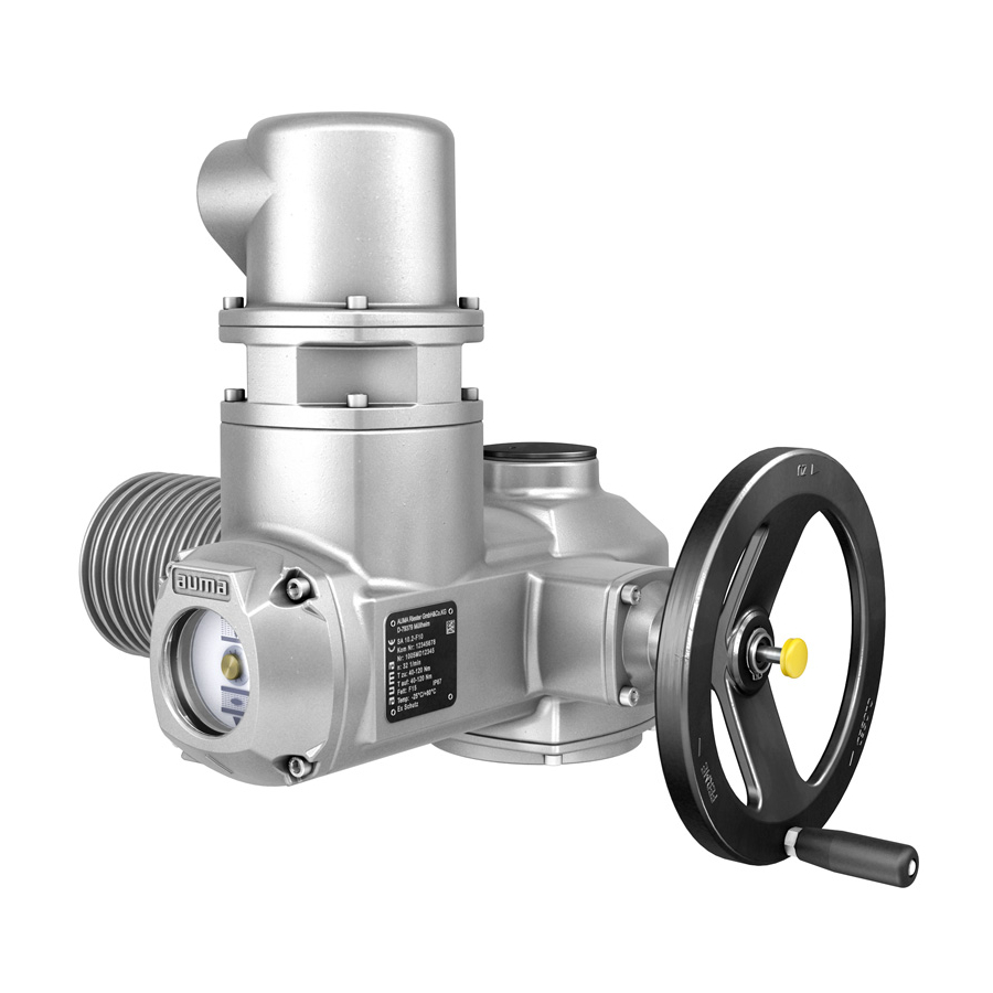
A multi-turn actuator is an actuator which transmits torque to a valve for at least one full revolution. AUMA multi-turn actuat- Figure 1: AUMA multi-turn actuator SAEx 10.2 Multi-turn actuator with motor and handwheel Actuator controls Local controls with display, (a) selector switch and (b) push button Valve connection, e.g. - Page 9 AUMA actuators at moderate cost. AUMA Cloud The AUMA Cloud collects all device data of all actuators within one site and provides a clear overview at a glance. Detailed analysis provides valuable information on potential maintenance requirements.
-
Page 10: Name Plate
SAEx 07.2 SAEx 16.2 / SAREx 07.2 SAREx 16.2 Control unit: electronic (MWG) Name plate ACExC 01.2 Non-Intrusive Modbus TCP/IP Name plate Figure 4: Arrangement of name plates Actuator name plate Actuator controls name plate Motor name plate Explosion protection approval plate Additional plate, e.g. - Page 11 Figure 6: Actuator controls name plate (= manufacturer logo) Type designation Order number Serial number Actuator terminal plan Actuator controls terminal plan Mains voltage AUMA power class for switchgear Permissible ambient temperature Enclosure protection [10] Control [11] Data Matrix code Motor name plate Figure 7: Motor name plate (example) (= manufacturer logo);...
- Page 12 Threads for line bushings at electrical connection Not used Descriptions referring to name plate indications Type designation Table 1: Description of type designation actuator (in our example: SAEx 07.2-F10) SAEx 07.2 -F10 SAEx Type SAEx = Multi-turn actuators for open-close duty Type SAREx = Multi-turn actuators for modulating duty 07.2...
- Page 13 The rated power (nominal power) of the actuator motor is indicated in kW on the motor name plate. For the assignment of the AUMA power classes to the nominal power of the motor types, refer to the separate electrical data sheets.
-
Page 14: Transport And Storage
Perform lift trial at low height to eliminate any potential danger e.g. by tilting. Figure 10: Example: Lifting the actuator Weights Table 6: Weight for ACExC 01.2 actuator controls with electrical connection type: Weight approx. [kg] AUMA Ex plug/socket connector with terminal blocks (KES), 16.5 flameproof enclosure Ex d... - Page 15 SAREx 16.2 ADX... Refer to motor name plate Indicated weight includes AUMA NORM multi-turn actuator with 3-phase AC motor, electrical con- nection in standard version, output drive type B1 and handwheel. For other output drive types, heed additional weights. Table 8: Weights of multi-turn actuators SAEx 07.2...
-
Page 16: Storage
SAEx 07.2 SAEx 16.2 / SAREx 07.2 SAREx 16.2 Control unit: electronic (MWG) Transport and storage ACExC 01.2 Non-Intrusive Modbus TCP/IP Table 9: Weights for output drive type Type designation Flange size [kg] A 07.2 A 10.2 A 14.2 A 16.2 11.7... -
Page 17: Assembly
SAEx 07.2 SAEx 16.2 / SAREx 07.2 SAREx 16.2 Control unit: electronic (MWG) ACExC 01.2 Non-Intrusive Modbus TCP/IP Assembly Assembly 5.1. Mounting position When using grease as lubricant, the product described herein can be operated in any mounting position. When using oil instead of grease within the actuator gear housing, perpendicular mounting position is specified whereby the flange is pointing downward. -
Page 18: Overview Of Output Drive Types
SAEx 07.2 SAEx 16.2 / SAREx 07.2 SAREx 16.2 Control unit: electronic (MWG) Assembly ACExC 01.2 Non-Intrusive Modbus TCP/IP 5.3.1. Overview of output drive types Table 10: Overview on output drive types Valve attachment Application Description Assembly for rising, non-rotating valve stem ➭... -
Page 19: 5.3.2.1. Multi-Turn Actuator With Output Drive Type A: Mount
SAEx 07.2 SAEx 16.2 / SAREx 07.2 SAREx 16.2 Control unit: electronic (MWG) ACExC 01.2 Non-Intrusive Modbus TCP/IP Assembly 5.3.2.1. Multi-turn actuator with output drive type A: mount If output drive type A is already mounted to the multi-turn actuator: Loosen screws [3] and remove output drive type A [2]. - Page 20 SAEx 07.2 SAEx 16.2 / SAREx 07.2 SAREx 16.2 Control unit: electronic (MWG) Assembly ACExC 01.2 Non-Intrusive Modbus TCP/IP Fit multi-turn actuator on the valve stem so that the stem nut dogs engage into the output drive sleeve. Figure 15: The flanges are flush with each other if properly engaged.
-
Page 21: 5.3.2.2. Stem Nut For Output Drive Type A: Finish Machining
This working step is only required if stem nut is supplied unbored or with pilot bore. Information For exact product version, please refer to the order-related technical data sheet or the AUMA Assistant App. Figure 17: Output drive type A Stem nut Axial needle roller bearing [2.1] Axial bearing washer... -
Page 22: Output Drive Types B/C/D And E
SAEx 07.2 SAEx 16.2 / SAREx 07.2 SAREx 16.2 Control unit: electronic (MWG) Assembly ACExC 01.2 Non-Intrusive Modbus TCP/IP 5.3.3. Output drive types B/C/D and E Figure 18: Mounting principle Flange multi-turn actuator (e.g. F07) Hollow shaft Output drive sleeve (illustration examples) -
Page 23: 5.3.3.1. Multi-Turn Actuator With Output Drive Type B: Mount
SAEx 07.2 SAEx 16.2 / SAREx 07.2 SAREx 16.2 Control unit: electronic (MWG) ACExC 01.2 Non-Intrusive Modbus TCP/IP Assembly 5.3.3.1. Multi-turn actuator with output drive type B: mount Figure 19: Mounting output drive types B Multi-turn actuator Valve/gearbox Valve/gearbox shaft Check if mounting flanges fit together. -
Page 24: Accessories For Assembly
SAEx 07.2 SAEx 16.2 / SAREx 07.2 SAREx 16.2 Control unit: electronic (MWG) Assembly ACExC 01.2 Non-Intrusive Modbus TCP/IP 5.4. Accessories for assembly 5.4.1. Stem protection tube for rising valve stem Figure 20: Assembly of the stem protection tube Protective cap for stem protection tube (fitted) -
Page 25: Mounting Positions Of Local Controls
SAEx 07.2 SAEx 16.2 / SAREx 07.2 SAREx 16.2 Control unit: electronic (MWG) ACExC 01.2 Non-Intrusive Modbus TCP/IP Assembly 5.4.2. Mounting positions of local controls Figure 22: Mounting positions The mounting position of the local controls is implemented according to the order. -
Page 26: Electrical Connection
The pertaining wiring diagram/terminal plan (in German or English) is attached to the device in a weather-proof bag, together with these operation instructions. It can plan also be requested from AUMA (state order number, refer to name plate) or downloaded directly from the Internet (http://www.auma.com). Permissible networks The actuators are suitable for use in TN and TT networks with directly grounded star point for nominal voltages up to maximum 690 V AC. - Page 27 5.5 kW 63 A (g/R) I²t<5,000A²s The AUMA power class (A1, B1, ...) is indicated on the actuator controls name plate Consider the motor starting current (IA) (refer to electrical data sheet) when selecting the circuit breaker. We recommend tripping characteristics D or K for circuit breakers in accordance with IEC 60947-2.
-
Page 28: Kes Electrical Connection
SAEx 07.2 SAEx 16.2 / SAREx 07.2 SAREx 16.2 Control unit: electronic (MWG) Electrical connection ACExC 01.2 Non-Intrusive Modbus TCP/IP For connecting cables exposed to UV radiation (outdoor installation), use UV resistant cables. For the connection of position transmitters, screened cables must be used. -
Page 29: Terminal Compartment: Open
SAEx 07.2 SAEx 16.2 / SAREx 07.2 SAREx 16.2 Control unit: electronic (MWG) ACExC 01.2 Non-Intrusive Modbus TCP/IP Electrical connection Cable entry via the connection frame. Cover in KES-Ex d version for terminal compartment in type of protection Ex d (flameproof enclosure). -
Page 30: Cable Connection
SAEx 07.2 SAEx 16.2 / SAREx 07.2 SAREx 16.2 Control unit: electronic (MWG) Electrical connection ACExC 01.2 Non-Intrusive Modbus TCP/IP Insert cable glands suitable for connecting cables. Information: When selecting cable glands, observe type of protection (with Ex e or Ex d approval) and enclosure protection IP (Refer to name plate). -
Page 31: Industrial Ethernet Cable: Connect
Power supply Cable connection For connecting cables to RJ-45 connectors, proceed in compliance with the connector manufacturer specifications. When using the RJ-45 connector supplied by AUMA, please heed the assembly instructions provided. Connect RJ-45 connector to port for Ethernet cable [1]. -
Page 32: Terminal Compartment: Close
SAEx 07.2 SAEx 16.2 / SAREx 07.2 SAREx 16.2 Control unit: electronic (MWG) Electrical connection ACExC 01.2 Non-Intrusive Modbus TCP/IP 6.2.4. Terminal compartment: close Figure 29: Close terminal compartment Cover (illustration shows type of protection Ex d) Screws for cover... -
Page 33: Accessories For Electrical Connection
SAEx 07.2 SAEx 16.2 / SAREx 07.2 SAREx 16.2 Control unit: electronic (MWG) ACExC 01.2 Non-Intrusive Modbus TCP/IP Electrical connection Figure 31: Earth connection for wall bracket External earth connection (U-bracket) for connection to equipotential compensation. Application Table 20: Terminal cross sections and earth connection tightening torques... -
Page 34: Parking Frame
The permissible cable length between actuator controls on wall bracket and the actuator amounts to 100 m maximum. We recommend using an AUMA “LSW” cable set. If the AUMA cable set is not used: Use suitable flexible and screened connecting cables. -
Page 35: Operation
SAEx 07.2 SAEx 16.2 / SAREx 07.2 SAREx 16.2 Control unit: electronic (MWG) ACExC 01.2 Non-Intrusive Modbus TCP/IP Operation Operation 7.1. Manual operation For purposes of setting and commissioning, in case of motor or power failure, the actuator may be operated manually. Manual operation is engaged by an internal change-over mechanism. -
Page 36: Motor Operation
SAEx 07.2 SAEx 16.2 / SAREx 07.2 SAREx 16.2 Control unit: electronic (MWG) Operation ACExC 01.2 Non-Intrusive Modbus TCP/IP Figure 35: Handwheel without/with overload protection Handwheel without overload protection (standard) Handwheel with overload protection/safety hub (option) 7.2. Motor operation Valve damage due to incorrect basic setting! Prior to electric actuator operation, perform the basic settings for “type of seating”... -
Page 37: Actuator Operation From Remote
SAEx 07.2 SAEx 16.2 / SAREx 07.2 SAREx 16.2 Control unit: electronic (MWG) ACExC 01.2 Non-Intrusive Modbus TCP/IP Operation Hot surfaces, e.g. possibly caused by high ambient temperatures or strong direct sunlight! Risk of burns Verify surface temperature and wear protective gloves. -
Page 38: Menu Layout And Navigation
SAEx 07.2 SAEx 16.2 / SAREx 07.2 SAREx 16.2 Control unit: electronic (MWG) Operation ACExC 01.2 Non-Intrusive Modbus TCP/IP Figure 37: [1 4] Push buttons or navigation support Selector switch Display Table 22: Important push button functions for menu navigation... -
Page 39: User Level, Password
SAEx 07.2 SAEx 16.2 / SAREx 07.2 SAREx 16.2 Control unit: electronic (MWG) ACExC 01.2 Non-Intrusive Modbus TCP/IP Operation Figure 39: Marking with ID ID starts with = status menu ID starts with = main menu It is possible to select between status menu S and main menu M: Group selection For this, set selector switch to 0 (OFF), hold down push button C for approx. -
Page 40: Password Entry
SAEx 07.2 SAEx 16.2 / SAREx 07.2 SAREx 16.2 Control unit: electronic (MWG) Operation ACExC 01.2 Non-Intrusive Modbus TCP/IP Table 23: User levels and authorisations Designation (user level) Authorisation/password Observer (1) Verify settings No password required Operator (2) Change settings... -
Page 41: Timeout For Incorrect Password Entry
A timeout for incorrect password entry is provided with actuator controls.This prevents unauthorised access by systematic trials. The timeout is active for incorrect entries via the local controls as well as incorrect entries via our software tools (AUMA CDT, AUMA Assistant App). After five subsequent incorrect trials, further entry is inhibited for one minute. - Page 42 SAEx 07.2 SAEx 16.2 / SAREx 07.2 SAREx 16.2 Control unit: electronic (MWG) Operation ACExC 01.2 Non-Intrusive Modbus TCP/IP The bottom row of the display indicates: Save → continue with step 10 Edit → continue with step 6 Press Edit.
-
Page 43: Indications
If no entry is made over a longer period of time (approx. 1 minute), the display automatically returns to the first status indication. 8.2. Indications in the display Menus and functions depend on the actuator controls firmware version! Should menus or functions be unavailable, please contact the AUMA Service. -
Page 44: Feedback Signals From Actuator And Valve
SAEx 07.2 SAEx 16.2 / SAREx 07.2 SAREx 16.2 Control unit: electronic (MWG) Indications ACExC 01.2 Non-Intrusive Modbus TCP/IP The status bar (first row in the display) indicates the operation mode [1], the presence Status bar of an error [2] and the ID number [3] of the current display indication. - Page 45 SAEx 07.2 SAEx 16.2 / SAREx 07.2 SAREx 16.2 Control unit: electronic (MWG) ACExC 01.2 Non-Intrusive Modbus TCP/IP Indications The bar graph display appears after approx. 3 seconds. Figure 51: Torque allows to select the unit displayed (percent %, Newton metre Nm...
- Page 46 SAEx 07.2 SAEx 16.2 / SAREx 07.2 SAREx 16.2 Control unit: electronic (MWG) Indications ACExC 01.2 Non-Intrusive Modbus TCP/IP Figure 54: Indication for setpoint control (positioner) Position setpoint Actual position value The pivot points and their operation behaviour (operation profile) are shown on the Pivot point axis pivot point axis by means of symbols.
-
Page 47: Status Indications According To Auma Classification
SAREx 16.2 Control unit: electronic (MWG) ACExC 01.2 Non-Intrusive Modbus TCP/IP Indications 8.2.2. Status indications according to AUMA classification These indications are available if the parameter Diagnostic classific. M0539 is set to AUMA. Warnings (S0005) If a warning has occurred, the display shows S0005: the number of warnings occurred a blinking question mark after approx. - Page 48 SAEx 07.2 SAEx 16.2 / SAREx 07.2 SAREx 16.2 Control unit: electronic (MWG) Indications ACExC 01.2 Non-Intrusive Modbus TCP/IP the number of indications occurred a blinking triangle with question mark after approx. 3 seconds Figure 60: Out of specification For further information, please also refer to <Corrective action>.
-
Page 49: Indication Lights Of Local Controls
SAEx 07.2 SAEx 16.2 / SAREx 07.2 SAREx 16.2 Control unit: electronic (MWG) ACExC 01.2 Non-Intrusive Modbus TCP/IP Indications Figure 63: Failure For further information, please also refer to <Corrective action>. 8.3. Indication lights of local controls Figure 64: Arrangement and signification of indication lights... -
Page 50: Signals (Output Signals)
SAEx 07.2 SAEx 16.2 / SAREx 07.2 SAREx 16.2 Control unit: electronic (MWG) Signals (output signals) ACExC 01.2 Non-Intrusive Modbus TCP/IP Signals (output signals) 9.1. Status signals via output contacts (digital outputs) Output contacts are only available if a parallel interface is provided in addition to the Conditions communication interface. -
Page 51: Commissioning (Basic Settings)
The actuator type is set in the factory but can be modified at a later date. Required user level: Specialist (4) or higher. Customer settings M0041 Multiport valve M1140 Actuator type M1142 Default value: Actuator type set in the factory Setting ranges: Selection list of all AUMA actuators... -
Page 52: Gear Reduction Ratio: Set/Check
Required user level: Specialist (4) or higher. Customer settings M0041 Multiport valve M1140 Reduction ratio M1143 Default values: GS50.3 Setting values: Table 25: Selection of gearboxes supported by AUMA Sizes GS 50.3 GS 125.3 Sizes GS160.3 GS 250.3 GS50.3 GS160.3 GS63.3... -
Page 53: Positions (Of Valve Ports): Define/Check
SAEx 07.2 SAEx 16.2 / SAREx 07.2 SAREx 16.2 Control unit: electronic (MWG) ACExC 01.2 Non-Intrusive Modbus TCP/IP Commissioning (basic settings) Multiport valve M1140 MPV home port M1162 Set? Successful homeport setting is visualised by a black circle on the actuator controls display: . -
Page 54: Operate To Position Via Push Buttons Of The Local Controls
SAEx 07.2 SAEx 16.2 / SAREx 07.2 SAREx 16.2 Control unit: electronic (MWG) Commissioning (basic settings) ACExC 01.2 Non-Intrusive Modbus TCP/IP Position 7 = 270.0 Position 8 = 315.0 The positions must be set in subsequent sequence (descending/ascending). 10.1.6. Operate to position via push buttons of the local controls To operate to a position via push buttons of the local controls, status indication S0017 must be shown (refer to <Indications in the display>). -
Page 55: Operate To Position From Remote
SAEx 07.2 SAEx 16.2 / SAREx 07.2 SAREx 16.2 Control unit: electronic (MWG) ACExC 01.2 Non-Intrusive Modbus TCP/IP Commissioning (basic settings) Symbol Set positions (of valve ports) (P1, P2, ...) selected position (1, 2, ...) / N/A No position has been selected. -
Page 56: Dead Band
SAEx 07.2 SAEx 16.2 / SAREx 07.2 SAREx 16.2 Control unit: electronic (MWG) Commissioning (basic settings) ACExC 01.2 Non-Intrusive Modbus TCP/IP A digital input is used to select the desired operation to the next port including the direction of operation. Thus, up to 16 ports can be approached in both directions, even without fieldbus connection with only 2 inputs. -
Page 57: 10.1.12. Hysteresis For Signalling Intermediate Positions: Set
Figure 70: Switching behaviour for signalling behaviours B, C, D and hysteresis 3.0°. Switch-on point ( ● ) Switch-off point (○) Pulse duration = 2 times XT + hysteresis Required user level: AUMA (6). Customer settings M0041 Multiport valve M1140 Hysteresis M1148... -
Page 58: Torque Switching: Set
SAEx 07.2 SAEx 16.2 / SAREx 07.2 SAREx 16.2 Control unit: electronic (MWG) Commissioning (basic settings) ACExC 01.2 Non-Intrusive Modbus TCP/IP Default values: 0.5° for all 16 intermediate positions Setting range:0.0° to 5.0° (degree) 10.2. Torque switching: set Once the set torque is reached, the torque switches will be tripped (overload protection of the valve). -
Page 59: Fieldbus Address (Slave Address), Baud Rate, Parity And Monitoring Time: Set
Parity/stop bit = Even, 1 stop bit Monitoring time = 15 seconds Information Parameter MD2 slave address is only available if AUMA redundancy I (option) is available. For further settings and information e.g. on redundancy, refer to Manual (Device integration). -
Page 60: Test Run
SAEx 07.2 SAEx 16.2 / SAREx 07.2 SAREx 16.2 Control unit: electronic (MWG) Commissioning (basic settings) ACExC 01.2 Non-Intrusive Modbus TCP/IP Table 26: Default setting of the IP interface: Address Type Static IP Static IP Address 192.168.255.1 Subnet Mask 255.255.0.0 Default Gateway 192.168.0.1... -
Page 61: Limit Switching: Check
SAEx 07.2 SAEx 16.2 / SAREx 07.2 SAREx 16.2 Control unit: electronic (MWG) ACExC 01.2 Non-Intrusive Modbus TCP/IP Commissioning (basic settings) 10.4.2. Limit switching: check Set selector switch to position Local control (LOCAL). Operate actuator using push buttons OPEN, STOP, CLOSE. -
Page 62: Corrective Action
SAEx 07.2 SAEx 16.2 / SAREx 07.2 SAREx 16.2 Control unit: electronic (MWG) Corrective action ACExC 01.2 Non-Intrusive Modbus TCP/IP Corrective action 11.1. Faults during commissioning Table 27: Faults during operation/commissioning Fault Description/cause Remedy Mechanical position indicator cannot Reduction gearing is not suitable for turns/stroke Set gear stage of the reduction gearing. - Page 63 SAEx 07.2 SAEx 16.2 / SAREx 07.2 SAREx 16.2 Control unit: electronic (MWG) ACExC 01.2 Non-Intrusive Modbus TCP/IP Corrective action Table 29: Warnings and Out of specification Indication on display Description/cause Remedy Config. warning Collective signal 06: Press push button...
- Page 64 SAEx 07.2 SAEx 16.2 / SAREx 07.2 SAREx 16.2 Control unit: electronic (MWG) Corrective action ACExC 01.2 Non-Intrusive Modbus TCP/IP Table 30: Faults and Failure Indication on display Description/cause Remedy Configuration error Collective signal 11: Press push button Details to display a list of de- Configuration error has occurred.
- Page 65 Selector switch is not in position REMOTE. Set selector switch to position REMOTE. Service active Operation via service interface (Bluetooth) and Exit service software. AUMA CDT service software. Disabled Actuator is in operation mode Disabled. Check setting and status of function <Local controls enable>.
-
Page 66: Fuses
SAEx 07.2 SAEx 16.2 / SAREx 07.2 SAREx 16.2 Control unit: electronic (MWG) Corrective action ACExC 01.2 Non-Intrusive Modbus TCP/IP Not ready REMOTE and Function check (collective signal 04) Indication on display Description/cause Remedy Interlock bypass By-pass function is interlocked. -
Page 67: Test/Replace Fuses
SAEx 07.2 SAEx 16.2 / SAREx 07.2 SAREx 16.2 Control unit: electronic (MWG) ACExC 01.2 Non-Intrusive Modbus TCP/IP Corrective action Figure 72: Pull fuse holder out of pin carrier, open fuse cover and replace old fuses by new ones. 11.3.2.2. Test/replace fuses F3/F4 Loosen screws [1] and remove cover [2] on the rear of the actuator controls. - Page 68 SAEx 07.2 SAEx 16.2 / SAREx 07.2 SAREx 16.2 Control unit: electronic (MWG) Corrective action ACExC 01.2 Non-Intrusive Modbus TCP/IP The motor has to cool down before operation can be resumed. Depending on the parameter setting (motor protection behaviour), the fault signal is either automatically reset or the fault signal has to be acknowledged.
-
Page 69: Servicing And Maintenance
Therefore, we recommend contacting our service. Only perform servicing and maintenance tasks when the device is switched off. AUMA AUMA offers extensive service such as servicing and maintenance as well as Service & Support customer product training. For the contact addresses, refer to our website (www.auma.com). -
Page 70: Disconnection From The Mains
Remove electrical connection. For electrical connections of KES type, cover [1] and connection frame [4] remain assembled. Seal open plug/socket connection, e.g. using AUMA protection cover and parking frame. Fitting the plug: Clean sealing faces of plug/socket connector and housing. -
Page 71: Disposal And Recycling
Electrical connection cables must be placed properly and in perfect condition. Thoroughly touch up any possible damage to painting to prevent corrosion. Original paint in small quantities can be supplied by AUMA. Cables and wire entries, blanking plug, cable glands, plugs etc. have to be checked for correct tightness and sealing. - Page 72 SAEx 07.2 SAEx 16.2 / SAREx 07.2 SAREx 16.2 Control unit: electronic (MWG) Servicing and maintenance ACExC 01.2 Non-Intrusive Modbus TCP/IP Greases and oils are hazardous to water and must not be released into the environment. Arrange for controlled waste disposal of the disassembled material or for sep- arate recycling according to materials.
-
Page 73: Technical Data
Information on the customer-specific version, refer to the order-related data sheet. The technical data sheet can be downloaded from the Internet in both German and English at ht- tp://www.auma.com (please state the order number). 13.1. Technical data Multi-turn actuators Features and functions... - Page 74 Pollution degree 4 (when closed), pollution degree 2 (internal) 60664-1 Vibration resistance according to 2 g, 10 to 200 Hz (AUMA NORM), 1 g, 10 to 200 Hz (for actuators with AMExC or ACExC actuator IEC 60068-2-6 controls) Resistant to vibration during start-up or for failures of the plant. However, a fatigue strength may not be derived from this.
-
Page 75: Technical Data Actuator Controls
The reversing contactors are designed for a lifetime of 2 million starts. For applications requiring a high number of starts, we recommend the use of thyristor units. For the assignment of AUMA power classes, please refer to electrical data on actuator. Control and feedback signals... - Page 76 Bluetooth class II chip, version 2.1: With a range up to 10 m in industrial environments, supports the SPP Bluetooth profile (Serial Port Profile). Communication interface Required accessories: AUMA CDT (Commissioning and Diagnostic Tool for Windows-based PC) AUMA Assistant App (Commissioning and Diagnostic Tool) Application functions Standard:...
- Page 77 Option: Thermal overload relay in controls combined with thermoswitches within actuator Electrical connection Standard: AUMA Ex plug/socket connector with terminal blocks (KES), flameproof enclosure Ex d Options: AUMA Ex plug/socket connector (KT); screw-type motor terminals; push-in type control terminals Threads for cable entries...
- Page 78 SAEx 07.2 SAEx 16.2 / SAREx 07.2 SAREx 16.2 Control unit: electronic (MWG) Technical data ACExC 01.2 Non-Intrusive Modbus TCP/IP General Modbus TCP/IP data Communication protocol Modbus TCP/IP according to IEC 61158 and IEC 61784 Network topology Star topology/ point-to-point topology Transmission medium IEC IEEE 802.3, cable recommendation: Cat.
-
Page 79: Tightening Torques For Screws
Enclosure protection in accordance IP68 with IEC 60529 According to AUMA definition, enclosure protection IP68 meets the following requirements: Depth of water: Maximum 8 m head of water Continuous immersion in water: maximal 96 hours For exact version, refer to actuator controls name plate. -
Page 80: Spare Parts
SAEx 07.2 SAEx 16.2 / SAREx 07.2 SAREx 16.2 Control unit: electronic (MWG) Spare parts ACExC 01.2 Non-Intrusive Modbus TCP/IP Spare parts 14.1. Multi-turn actuators SAEx 07.2 SAEx 16.2/SAREx 07.2 SAREx 16.2 KES-Exd Motor (only for V... motors incl. ref. no. - Page 81 SAEx 07.2 SAEx 16.2 / SAREx 07.2 SAREx 16.2 Control unit: electronic (MWG) ACExC 01.2 Non-Intrusive Modbus TCP/IP Spare parts...
- Page 82 ACExC 01.2 Non-Intrusive Modbus TCP/IP Please state device type and our order number (see name plate) when ordering spare parts. Only original AUMA spare parts should be used. Failure to use original spare parts voids the warranty and exempts AUMA from any liability. Representation of spare parts may slightly vary from actual delivery.
-
Page 83: Acexc 01.2 Actuator Controls With Kes Electrical Connection
SAEx 07.2 SAEx 16.2 / SAREx 07.2 SAREx 16.2 Control unit: electronic (MWG) ACExC 01.2 Non-Intrusive Modbus TCP/IP Spare parts 14.2. ACExC 01.2 actuator controls with KES electrical connection... - Page 84 ACExC 01.2 Non-Intrusive Modbus TCP/IP Please state device type and our order number (see name plate) when ordering spare parts. Only original AUMA spare parts should be used. Failure to use original spare parts voids the warranty and exempts AUMA from any liability. Representation of spare parts may slightly vary from actual delivery.
-
Page 85: Index
SAEx 07.2 SAEx 16.2 / SAREx 07.2 SAREx 16.2 Control unit: electronic (MWG) ACExC 01.2 Non-Intrusive Modbus TCP/IP Index Index Earth connection Electrical connection Accessories (electrical con- Enclosure protection 10, 11, 11, 74, 79 nection) Error - indication on display... - Page 86 SAEx 07.2 SAEx 16.2 / SAREx 07.2 SAREx 16.2 Control unit: electronic (MWG) Index ACExC 01.2 Non-Intrusive Modbus TCP/IP Main menu Parity Mains frequency 11, 11 Parking frame Mains voltage 11, 11, 26 Password Maintenance 6, 69, 70 Password change...
- Page 87 SAEx 07.2 SAEx 16.2 / SAREx 07.2 SAREx 16.2 Control unit: electronic (MWG) ACExC 01.2 Non-Intrusive Modbus TCP/IP Index Safety instructions Wall bracket Safety instructions/warnings Warnings - indication on dis- Safety measures play Safety standards Wiring diagram 13, 26 Screw plugs...
- Page 88 AUMA Riester GmbH & Co. KG P.O. Box 1362 DE 79373 Muellheim Tel +49 7631 809 - 0 Fax +49 7631 809 - 1250 info@auma.com www.auma.com Y009.610/003/en/1.22 For detailed information on AUMA products, refer to the Internet: www.auma.com...
Need help?
Do you have a question about the SAEx 07.2 and is the answer not in the manual?
Questions and answers