AUMA SAEx 07.2 Operation Manual
Multi-turn actuators
Hide thumbs
Also See for SAEx 07.2:
- Manual (116 pages) ,
- Operation instructions manual (104 pages) ,
- Assembly instructions (3 pages)

Related Manuals for AUMA SAEx 07.2


Summary of Contents for AUMA SAEx 07.2
- Page 1 Multi-turn actuators SAEx 07.2 SAEx 16.2 SAREx 07.2 SAREx 16.2 AUMA NORM (without controls) Version FM/CSAEX (Class/Division system) Operation manual Assembly, operation, commissioning...
-
Page 2: Table Of Contents
SAEx 07.2 SAEx 16.2 / SAREx 07.2 SAREx 16.2 Table of contents Read operation manual first. Observe safety instructions. This operation manual is part of the product. Preserve operation manual during product life. Pass on manual to any subsequent user or owner of the product. - Page 3 SAEx 07.2 SAEx 16.2 / SAREx 07.2 SAREx 16.2 Table of contents 5.3.1. Parking frame 5.3.2. Protection cover 5.3.3. External PE connection Operation..........................6.1. Manual operation 6.1.1. Manual operation: engage 6.1.2. Manual operation: disengage 6.2. Motor operation Indications..........................7.1. Mechanical position indicator/running indication on indicator mark on cover Signals.............................
- Page 4 SAEx 07.2 SAEx 16.2 / SAREx 07.2 SAREx 16.2 Table of contents Spare parts..........................13.1. Multi-turn actuators SAEx 07.2 SAEx 16.2/SAREx 07.2 SAREx 16.2 KES Exd Certificates..........................14.1. Certificate of compliance, FM Approval Index............................Addresses..........................
-
Page 5: Safety Instructions
Any device modification requires prior consent of the manufacturer. 1.2. Range of application AUMA multi-turn actuators are designed for the operation of industrial valves, e.g. globe valves, gate valves, butterfly valves, and ball valves. The devices described below are approved for use in hazardous classified locations... -
Page 6: Warnings And Notes
SAEx 07.2 SAEx 16.2 / SAREx 07.2 SAREx 16.2 Safety instructions Other applications require explicit (written) confirmation by the manufacturer. The following applications are not permitted, e.g.: Industrial trucks Lifting appliances Passenger lifts Service lifts Escalators Continuous duty Buried service... -
Page 7: References And Symbols
SAEx 07.2 SAEx 16.2 / SAREx 07.2 SAREx 16.2 Safety instructions 1.4. References and symbols The following references and symbols are used in these instructions: Information The term Information preceding the text indicates important notes and information. Symbol for CLOSED (valve closed) Symbol for OPEN (valve open) Important information before the next step. -
Page 8: Identification
SAEx 07.2 SAEx 16.2 / SAREx 07.2 SAREx 16.2 Identification Identification 2.1. Name tag Each device component (actuator, motor) is equipped with a name tag. Figure 1: Arrangement of name tags Motor name tag Actuator name tag Additional plate, e.g. KKS plate (Power Plant Classification System) - Page 9 Flange size Ex marking Type and size This manual applies to the following device types and sizes: Multi-turn actuators for open-close duty: SAEx 07.2, 07.6, 10.2, 14.2, 14.6, 16.2 Multi-turn actuators for modulating duty: SAREx 07.2, 07.6, 10.2, 14.2, 14.6, 16.2...
-
Page 10: Short Description
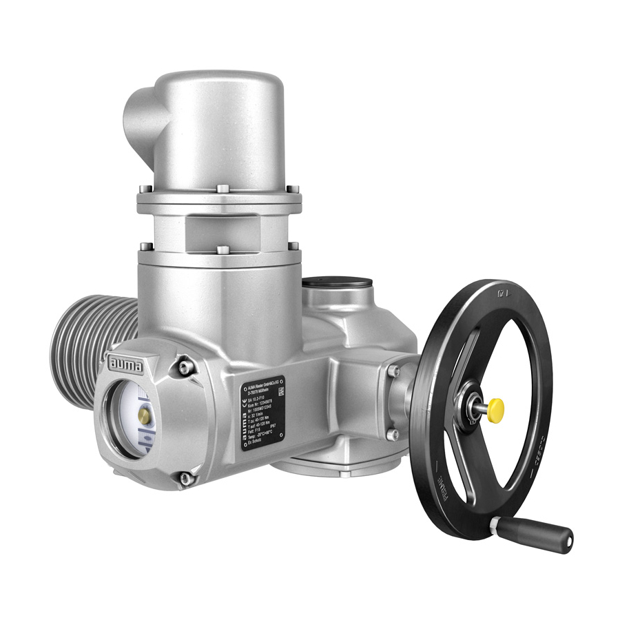
A multi-turn actuator is an actuator which transmits to the valve a torque for at least one full revolution. It is capable of withstanding thrust. AUMA multi-turn actuators are driven by an electric motor and are capable of withstanding thrust in combination with output drive type A. For manual operation, a handwheel is provided. -
Page 11: Transport, Storage And Packaging
SAEx 07.2 SAEx 16.2 / SAREx 07.2 SAREx 16.2 Transport, storage and packaging Transport, storage and packaging 3.1. Transport For transport to place of installation, use sturdy packaging. Hovering load! Death or serious injury possible. Do NOT stand below hovering load. -
Page 12: Assembly
SAEx 07.2 SAEx 16.2 / SAREx 07.2 SAREx 16.2 Assembly Assembly 4.1. Mounting position The product described in this document can be operated without restriction in any mounting position. 4.2. Handwheel fitting Information For transport reason, handwheels with a diameter 15.7 inches (400 mm) and larger are supplied separately within the scope of delivery. -
Page 13: 4.3.1.1. Stem Nut: Finish Machining
SAEx 07.2 SAEx 16.2 / SAREx 07.2 SAREx 16.2 Assembly Figure 6: Design of output drive type A Output mounting flange Stem nut with dog coupling Valve stem Information To adapt the actuators to available output drive types A with flanges FA10 and FA14 (year of manufacture: 2009 and earlier), an adapter is required. -
Page 14: 4.3.1.2. Multi-Turn Actuator (With Output Drive Type A): Mount To Valve
SAEx 07.2 SAEx 16.2 / SAREx 07.2 SAREx 16.2 Assembly Remove stem nut [1] together with axial needle roller bearings [2]. Remove axial bearing washers [2.1] and axial needle roller and cage assemblies [2.2] from stem nut [1]. Drill and bore stem nut [1] and cut thread. -
Page 15: Output Drive Types B
SAEx 07.2 SAEx 16.2 / SAREx 07.2 SAREx 16.2 Assembly Rotate multi-turn actuator until alignment of the mounting holes. Reinstall multi-turn actuator with screws [3]. 10. Reinstall screws [3] crosswise with a torque according to table. Table 3: Tightening torques for screws... -
Page 16: 4.3.2.1. Multi-Turn Actuator With Output Drive Types B: Mount To Valve/Gearbox
SAEx 07.2 SAEx 16.2 / SAREx 07.2 SAREx 16.2 Assembly Figure 9: Output drive type B Multi-turn actuator flange (e.g. FA07) Hollow shaft Output drive sleeve (illustration examples) [3] B/B1/B2 and [3]* B3/B4, respectively with bore and keyway Gearbox/valve shaft Information Spigot at valve flanges should be loose fit. -
Page 17: Accessories For Assembly
SAEx 07.2 SAEx 16.2 / SAREx 07.2 SAREx 16.2 Assembly Apply a small quantity of grease to the valve or gearbox stem [3]. Fit multi-turn actuator [1]. Information: Ensure that the spigot fits uniformly in the recess and that the mounting faces are in complete contact. - Page 18 SAEx 07.2 SAEx 16.2 / SAREx 07.2 SAREx 16.2 Assembly Push down the sealing ring [3] onto the housing. Information: For mounting segments, push down seals of segments down to the sleeve (connecting piece). Check whether protective cap for stem protection tube [2] is available, in perfect...
-
Page 19: Electrical Connection
SAEx 07.2 SAEx 16.2 / SAREx 07.2 SAREx 16.2 Electrical connection Electrical connection 5.1. Basic information Danger due to incorrect electrical connection Failure to observe this warning can result in death, serious injury, or property damage. The electrical connection must be carried out exclusively by suitably qualified per- sonnel. -
Page 20: Connecting Via Ex Plug & Socket Connector With Terminal Blocks (Kes)
SAEx 07.2 SAEx 16.2 / SAREx 07.2 SAREx 16.2 Electrical connection Figure 12: Motor name tag (example) Type of current Mains voltage Mains frequency (for 3-ph and 1-ph AC motors) Use suitable (voltage-proof) cables. Specify cables for the highest occurring rated Connecting cables voltage. -
Page 21: Cable Connection
SAEx 07.2 SAEx 16.2 / SAREx 07.2 SAREx 16.2 Electrical connection Hazardous voltage! Risk of electric shock. Disconnect device from the mains before opening. Loosen screws [2] and remove cover [1]. Insert cable glands suitable for connecting cables. Information: When selecting cable glands observe type of protection (with Ex d approval) and type of protection NEMA... - Page 22 SAEx 07.2 SAEx 16.2 / SAREx 07.2 SAREx 16.2 Electrical connection In case of a fault: Hazardous voltage while protective earth conductor is NOT connected! Risk of electric shock. Connect all protective earth conductors. Connect PE connection to external protective earth conductor of connecting cables.
-
Page 23: Terminal Compartment: Close
SAEx 07.2 SAEx 16.2 / SAREx 07.2 SAREx 16.2 Electrical connection 5.2.3. Terminal compartment: close Figure 16: Close terminal compartment Cover Screws for cover O-ring Blanking plugs Cable gland Frame Clean sealing faces of cover [1] and frame [6]. Preserve joint surfaces with an acid-free corrosion protection agent. -
Page 24: Protection Cover
SAEx 07.2 SAEx 16.2 / SAREx 07.2 SAREx 16.2 Electrical connection Figure 17: Parking frame and Ex plug & socket connector with terminal blocks (KES) 5.3.2. Protection cover Option Application Protection cover for plug compartment when plug is removed. The open terminal compartment can be closed using a protective cover (not illustrated). -
Page 25: Operation
SAEx 07.2 SAEx 16.2 / SAREx 07.2 SAREx 16.2 Operation Operation 6.1. Manual operation For purposes of setting and commissioning, in case of motor failure or power failure, the actuator may be operated manually. Manual operation is engaged by an internal change-over mechanism. -
Page 26: Indications
SAEx 07.2 SAEx 16.2 / SAREx 07.2 SAREx 16.2 Indications Indications 7.1. Mechanical position indicator/running indication on indicator mark on cover Option Figure 19: Mechanical position indicator via indicator mark on cover End position OPEN reached End position CLOSED reached... -
Page 27: Signals
SAEx 07.2 SAEx 16.2 / SAREx 07.2 SAREx 16.2 Signals Signals 8.1. Feedback signals from actuator Information The switches can be provided as single switches (1 NC and 1 NO), as tandem switches (2 NC and 2 NO) or as triple switches (3 NC and 3 NO). The precise version is indicated in the terminal plan or on the order-related technical data sheet. -
Page 28: Commissioning
SAEx 07.2 SAEx 16.2 / SAREx 07.2 SAREx 16.2 Commissioning Commissioning 9.1. Switch compartment: open The switch compartment must be opened to perform the following settings (options). Flameproof enclosure, danger of explosion! Risk of death or serious injury. Before opening, ensure that there is no explosive gas and no voltage. -
Page 29: Limit Switch Setting
SAEx 07.2 SAEx 16.2 / SAREx 07.2 SAREx 16.2 Commissioning Valve damage due to excessive tripping torque limit setting! The tripping torque must suit the valve. Only change the setting with the consent of the valve manufacturer. Figure 20: Torque measuring heads... -
Page 30: End Position Closed (Black Section): Set
SAEx 07.2 SAEx 16.2 / SAREx 07.2 SAREx 16.2 Commissioning Figure 21: Setting components for limit switches Closed section black: Setting spindle: End position CLOSED Pointer: End position CLOSED Mark: End position CLOSED is set Open section white Setting spindle: End position OPEN... -
Page 31: Intermediate Positions: Set
SAEx 07.2 SAEx 16.2 / SAREx 07.2 SAREx 16.2 Commissioning As soon as the pointer [5] moves to mark [6]: Stop turning and release setting spindle. The end position OPEN setting is complete. If you override the tripping point inadvertently (ratchet click is heard after the pointer has snapped): Continue turning the setting spindle in the same direction and repeat setting process. -
Page 32: Running Direction Open (White Section): Set
SAEx 07.2 SAEx 16.2 / SAREx 07.2 SAREx 16.2 Commissioning As soon as the pointer [2] moves to mark [3]: Stop turning and release setting spindle. The intermediate position setting in running direction CLOSE is complete. If you override the tripping point inadvertently (ratchet click is heard after the pointer has rotated): Continue turning the setting spindle in the same direction and repeat setting process. - Page 33 SAEx 07.2 SAEx 16.2 / SAREx 07.2 SAREx 16.2 Commissioning With indicator disc: Observe direction of rotation. The direction of rotation is correct, if the actuator moves in direction CLOSE and: For position indication with symbols OPEN/CLOSED = indicator disk turns counterclockwise.
-
Page 34: Limit Switch Checking
SAEx 07.2 SAEx 16.2 / SAREx 07.2 SAREx 16.2 Commissioning 9.5.2. Limit switch checking Move actuator manually into both end positions of the valve. The limit switches are set correctly if: LSC switch trips in end position CLOSED LSO switch trips in end position OPEN the switches release the contacts after turning back the handwheel If the end position setting is incorrect: Reset limit switches. -
Page 35: Measuring Range: Set
SAEx 07.2 SAEx 16.2 / SAREx 07.2 SAREx 16.2 Commissioning The output current (measuring range 0 20 mA) can be checked at measuring points [1] and [2]. Table 8: Short overview on push button functions Push buttons Function [S1] + [S2] →... -
Page 36: Current Values: Adjust
SAEx 07.2 SAEx 16.2 / SAREx 07.2 SAREx 16.2 Commissioning Operate valve into opposite end position. The value set in end position (0/4 mA or 20 mA) does not change during travel in setting mode. Perform setting in the second end position following the same steps. -
Page 37: Potentiometer Setting
SAEx 07.2 SAEx 16.2 / SAREx 07.2 SAREx 16.2 Commissioning Figure 26: View on control unit Potentiometer 9.7.1. Potentiometer setting Information Due to the ratio of the reduction gearing, the complete resistance range/stroke is not always covered. Therefore, external adjustment (setting potentiometer) must be provided. -
Page 38: Measuring Range: Set
SAEx 07.2 SAEx 16.2 / SAREx 07.2 SAREx 16.2 Commissioning Figure 27: View on control unit when switch compartment is open Potentiometer (travel sensor) Potentiometer min. (0/4 mA) Potentiometer max. (20 mA) Measuring point (+) 0/4 20 mA Measuring point ( ) 0/4... -
Page 39: Switch Compartment: Close
SAEx 07.2 SAEx 16.2 / SAREx 07.2 SAREx 16.2 Commissioning Turn lower indicator disc until symbol (CLOSED) is in alignment with the mark on the cover. Move actuator to end position OPEN. Hold lower indicator disc in position and turn upper disc with symbol... - Page 40 SAEx 07.2 SAEx 16.2 / SAREx 07.2 SAREx 16.2 Commissioning Flameproof enclosure, danger of explosion! Risk of death or serious injury. Handle cover and housing parts with care. Joint surfaces must not be damaged or soiled in any way. Do not jam cover during fitting.
-
Page 41: Corrective Action
SAEx 07.2 SAEx 16.2 / SAREx 07.2 SAREx 16.2 Corrective action Corrective action 10.1. Faults during commissioning Table 11: Faults during commissioning Fault Description/cause Remedy Mechanical position indicator cannot Reduction gearing is not suitable for turns/stroke of Exchange reduction gearing. - Page 42 SAEx 07.2 SAEx 16.2 / SAREx 07.2 SAREx 16.2 Corrective action Overload, running time exceeded, max. number of starts exceeded, ambient temperature Possible causes is too high. Check cause, eliminate if possible. Remedy...
-
Page 43: Servicing And Maintenance
Only perform servicing and maintenance tasks when the device is switched off. AUMA AUMA offers extensive service such as servicing and maintenance as well as customer Service & Support product training. For the relevant contact addresses, please refer to <Addresses> in this document or to the Internet (www.auma-usa.com) -
Page 44: Disconnection From The Mains
Removing the plug: Remove plug & socket connector. For plug & socket connectors of KES type, cover [1] and frame [4] remain assembled. Seal open plug & socket connections, e.g. using AUMA protection covers and parking frames. Reinstalling the plug &... -
Page 45: Maintenance
11.4. Disposal and recycling AUMA devices have a long lifetime. However, they have to be replaced at one point in time. The devices have a modular design and may, therefore, easily be separated and sorted according to materials used, i.e.:... -
Page 46: Technical Data
The following tables include standard and optional features. For detailed information on the customer-specific version, refer to the order-specific data sheet. This technical data sheet can be downloaded from the Internet in both German and English at http://www.auma.com (please state the order number [commission number]). 12.1. Technical data Multi-turn actuators... - Page 47 SAEx 07.2 SAEx 16.2 / SAREx 07.2 SAREx 16.2 Technical data Electromechanical control unit Limit switches Counter gear mechanism for end positions OPEN and CLOSED Turns per stroke: 2 to 500 (standard) or 2 to 5,000 (option) Standard: Tandem switch (2 NC and 2 NO) for each end position, switches galvanically isolated...
- Page 48 Coating Double layer powder coating Two-component iron-mica combination Color Standard: AUMA silver-gray (similar to RAL 7037) Option: Available colors on request Lifetime The multi-turn actuators meet or exceed the lifetime requirements of EN 15714-2. Detailed information can be provided on request.
- Page 49 SAEx 07.2 SAEx 16.2 / SAREx 07.2 SAREx 16.2 Spare parts Spare parts 13.1. Multi-turn actuators SAEx 07.2 – SAEx 16.2/SAREx 07.2 – SAREx 16.2 KES Exd...
- Page 50 Spare parts Please state device type and our order number (see name tag) when ordering spare parts. Only original AUMA spare parts should be used. Failure to use original spare parts voids the warranty and exempts AUMA from any liability. Delivered spare parts may slightly vary from the representation in these instructions.
- Page 51 SAEx 16.2 / SAREx 07.2 SAREx 16.2 Certificates Certificates Information Certificates are valid as from the indicated date of issue. Subject to changes without notice. The latest versions are available for download at http://www.auma.com. 14.1. Certificate of compliance, FM Approval...
- Page 52 SAEx 07.2 SAEx 16.2 / SAREx 07.2 SAREx 16.2 Certificates...
- Page 53 SAEx 07.2 SAEx 16.2 / SAREx 07.2 SAREx 16.2 Certificates...
- Page 54 SAEx 07.2 SAEx 16.2 / SAREx 07.2 SAREx 16.2 Certificates...
- Page 55 SAEx 07.2 SAEx 16.2 / SAREx 07.2 SAREx 16.2 Index Index Identification Indications Indicator disc Accessories (electrical con- Indicator mark nection) Intermediate positions Accessories for assembly Inverse operation (0/20 Ambient temperature 8, 48 Applications Approval plate Assembly LED end position signaling...
- Page 56 SAEx 07.2 SAEx 16.2 / SAREx 07.2 SAREx 16.2 Index Range of application Recycling Running indication Safety instructions Safety instructions/warnings Serial number 8, 10 Service Servicing Short-circuit protection Signals Size Spare parts Speed Standards Stem nut Stem protection tube Storage...
- Page 57 GRØNBECH & SØNNER A/S AUMA BENELUX B.V. DK 2450 København SV NL 2314 XT Leiden Tel +45 33 26 63 00 Tel +31 71 581 40 40 AUMA Riester GmbH & Co. KG GS@g-s.dk office@auma.nl www.g-s.dk www.auma.nl Location Muellheim DE 79373 Muellheim IBEROPLAN S.A.
- Page 58 MANZ INCORPORATED LTD. info@arfajengg.com NG Port Harcourt Asia www.arfajengg.com Tel +234-84-462741 mail@manzincorporated.com AUMA Actuators UAE Support Office TOO “Armaturny Center” www.manzincorporated.com KZ 060005 Atyrau AE 287 Abu Dhabi Tel +971 26338688 Tel +7 7122 454 602 AUMA South Africa (Pty) Ltd.
- Page 59 Top Advance Enterprises Ltd. TW Jhonghe City, Taipei Hsien (235) Tel +886 2 2225 1718 support@auma-taiwan.com.tw www.auma-taiwan.com.tw AUMA Vietnam Hanoi RO VN Hanoi +84 4 37822115 chiennguyen@auma.com.vn Australia BARRON GJM Pty. Ltd. AU NSW 1570 Artarmon Tel +61 2 8437 4300 info@barron.com.au...
- Page 60 AUMA Actuators, Inc. 100 Southpointe Blvd USA Canonsburg PA 15317 Tel +1 724-743-2862 Fax +1 724-743-4711 mailbox@auma-usa.com www.auma-usa.com Y007.280/065/us/1.16 For detailed information on AUMA products, refer to the Internet: www.auma.com...
Need help?
Do you have a question about the SAEx 07.2 and is the answer not in the manual?
Questions and answers