AUMA SAEx 07.2 Operation Instructions Manual
Multi-turn actuators
Hide thumbs
Also See for SAEx 07.2:
- Manual (116 pages) ,
- Operation instructions manual (104 pages) ,
- Operation manual (60 pages)

Related Manuals for AUMA SAEx 07.2


Summary of Contents for AUMA SAEx 07.2
- Page 1 Multi-turn actuators SAEx 07.2 SAEx 16.2 SAREx 07.2 SAREx 16.2 AUMA NORM actuator (without controls) Operation instructions Assembly, operation, commissioning...
-
Page 2: Table Of Contents
Multi-turn actuator with output drive type B: mount 5.4. Accessories for assembly 5.4.1. Stem protection tube for rising valve stem Electrical connection......................6.1. Basic information 6.2. Overview of AUMA electrical connections 6.3. KT/KM electrical connection 6.3.1. Terminal compartment: open 6.3.2. Cable connection 6.3.3. Terminal compartment: close 6.4. - Page 3 SAEx 07.2 SAEx 16.2 / SAREx 07.2 SAREx 16.2 Table of contents 6.6. External earth connection 6.7. Accessories for electrical connection 6.7.1. Parking frame Operation..........................7.1. Manual operation 7.1.1. Manual valve operation 7.2. Motor operation Indications (optional)......................8.1. Mechanical position indication via indicator mark Signals (output signals)......................
- Page 4 SAEx 07.2 SAEx 16.2 / SAREx 07.2 SAREx 16.2 Table of contents Spare parts..........................15.1. Multi-turn actuators SA(V)Ex 07.2 SA(V)Ex 16.2/SAR(V)Ex 07.2 SAR(V)Ex 16.2 KT/KM 15.2. Multi-turn actuators SA(V)Ex 07.2 SA(V)Ex 16.2 / SAR(V)Ex 07.2 SAR(V)Ex 16.2 KP 15.3. Multi-turn actuators SA(V)Ex 07.2 SA(V)Ex 16.2 / SAR(V)Ex 07.2...
-
Page 5: Safety Instructions
SAEx 07.2 SAEx 16.2 / SAREx 07.2 SAREx 16.2 Safety instructions Safety instructions 1.1. Prerequisites for the safe handling of the product The end user or the contractor must ensure that all legal requirements, directives, Standards/directives guidelines, national regulations and recommendations with respect to assembly, electrical connection, commissioning and operation are met at the place of installation. -
Page 6: Range Of Application
1, 2, 21, and 22. If temperatures >40 °C are to be expected at the valve flange or the valve stem (e.g. due to hot media), please consult AUMA. Temperatures > 40 °C are not considered with regards to the non-electrical explosion protection. -
Page 7: Warnings And Notes
SAEx 07.2 SAEx 16.2 / SAREx 07.2 SAREx 16.2 Safety instructions 1.3. Warnings and notes The following warnings draw special attention to safety-relevant procedures in these operation instructions, each marked by the appropriate signal word (DANGER, WARNING, CAUTION, NOTICE). Indicates an imminently hazardous situation with a high level of risk. Failure to observe this warning results in death or serious injury. -
Page 8: Short Description
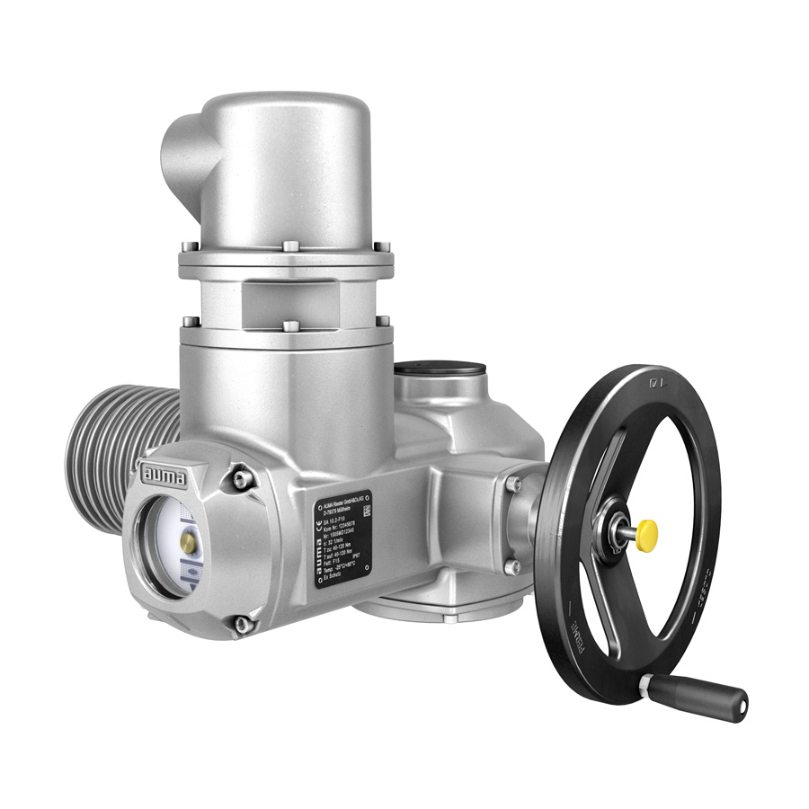
A handwheel is available for setting and emergency operation. Actuator controls are required to operate or process the actuator signals. Actuators without controls can be equipped with AUMA actuator controls at a later date. For more information, please state our order number (refer to actuator name plate). -
Page 9: Name Plate
SAEx 07.2 SAEx 16.2 / SAREx 07.2 SAREx 16.2 Name plate Name plate Figure 2: Arrangement of name plates Motor name plate Actuator name plate Additional plate, e.g. KKS plate (Power Plant Classification System) Explosion protection approval plate Actuator name plate Figure 3: Actuator name plate (example) (= manufacturer logo);... - Page 10 SAEx 07.2 SAEx 16.2 / SAREx 07.2 SAREx 16.2 Name plate Motor name plate Figure 4: Motor name plate (example) (= manufacturer logo); (= CE mark) Motor type Motor article number Serial number Current type, mains voltage Rated power Nominal current...
- Page 11 Internal number for unambiguous product identification Data Matrix code When registered as authorised user, you may use our AUMA Assistant App to scan the Data Matrix code and directly access the order-related product documents without having to enter order number or serial number.
-
Page 12: Transport And Storage
Perform lift trial at low height to eliminate any potential danger e.g. by tilting. Figure 7: Example: Lifting the actuator Weights Table 4: Weights of multi-turn actuators SAEx 07.2 SAEx 16.2 / SAREx 07.2 SAREx 16.2 with 3-phase AC motors... - Page 13 SAREx 16.2 ADX... Refer to motor name plate Indicated weight includes AUMA NORM multi-turn actuator with 3-phase AC motor, electrical con- nection in standard version, output drive type B1 and handwheel. For other output drive types, heed additional weights. Table 5: Weights of multi-turn actuators SAEx 07.2...
-
Page 14: Storage
SAEx 07.2 SAEx 16.2 / SAREx 07.2 SAREx 16.2 Transport and storage 4.2. Storage Danger of corrosion due to inappropriate storage! Store in a well-ventilated, dry room. Protect against floor dampness by storage on a shelf or on a wooden pallet. -
Page 15: Assembly
SAEx 07.2 SAEx 16.2 / SAREx 07.2 SAREx 16.2 Assembly Assembly 5.1. Mounting position When using grease as lubricant, the product described herein can be operated in any mounting position. When using oil instead of grease within the actuator gear housing, perpendicular mounting position is specified whereby the flange is pointing downward. -
Page 16: Overview Of Output Drive Types
SAEx 07.2 SAEx 16.2 / SAREx 07.2 SAREx 16.2 Assembly 5.3.1. Overview of output drive types Table 7: Overview on output drive types Valve attachment Application Description Assembly for rising, non-rotating valve stem ➭ page 16, Output drive type A ➭... -
Page 17: 5.3.2.1. Multi-Turn Actuator With Output Drive Type A: Mount
SAEx 07.2 SAEx 16.2 / SAREx 07.2 SAREx 16.2 Assembly 5.3.2.1. Multi-turn actuator with output drive type A: mount If output drive type A is already mounted to the multi-turn actuator: Loosen screws [3] and remove output drive type A [2]. - Page 18 SAEx 07.2 SAEx 16.2 / SAREx 07.2 SAREx 16.2 Assembly Fit multi-turn actuator on the valve stem so that the stem nut dogs engage into the output drive sleeve. Figure 12: The flanges are flush with each other if properly engaged.
-
Page 19: 5.3.2.2. Stem Nut For Output Drive Type A: Finish Machining
This working step is only required if stem nut is supplied unbored or with pilot bore. Information For exact product version, please refer to the order-related technical data sheet or the AUMA Assistant App. Figure 14: Output drive type A Stem nut Axial needle roller bearing [2.1] Axial bearing washer... -
Page 20: Output Drive Types B /C /D And E
SAEx 07.2 SAEx 16.2 / SAREx 07.2 SAREx 16.2 Assembly 5.3.3. Output drive types B /C /D and E Figure 15: Mounting principle Flange multi-turn actuator (e.g. F07) Hollow shaft Output drive sleeve (illustration examples) Gearbox/valve shaft Connection between hollow shaft and valve or gearbox via output drive sleeve fixed Short description to the hollow shaft of the multi-turn actuator via retaining ring. -
Page 21: 5.3.3.1. Multi-Turn Actuator With Output Drive Type B: Mount
SAEx 07.2 SAEx 16.2 / SAREx 07.2 SAREx 16.2 Assembly 5.3.3.1. Multi-turn actuator with output drive type B: mount Figure 16: Mounting output drive types B Multi-turn actuator Valve/gearbox Valve/gearbox shaft Procedure Check if mounting flanges fit together. Check if output drive of multi-turn actuator [1] matches the output drive of valve/gearbox or valve/gearbox valve shaft [2/3]. -
Page 22: Accessories For Assembly
SAEx 07.2 SAEx 16.2 / SAREx 07.2 SAREx 16.2 Assembly 5.4. Accessories for assembly 5.4.1. Stem protection tube for rising valve stem Figure 17: Assembly of the stem protection tube Protective cap for stem protection tube (fitted) [1]* Option: Protective cap made of steel (screwed) -
Page 23: Electrical Connection
Wiring diagram/terminal the device in a weather-proof bag, together with these operation instructions. It can plan also be requested from AUMA (state order number, refer to name plate) or downloaded directly from the Internet (http://www.auma.com). Valve damage for connection without controls! NORM actuators require controls: Connect motor via actuator controls only (reversing contactor circuit). -
Page 24: Overview Of Auma Electrical Connections
For the connection of position transmitters, screened cables must be used. 6.2. Overview of AUMA electrical connections The section below provides an overview of the different electrical connections described in the chapters to follow. Table 10: Versions of the AUMA plug/socket connector Electrical con- Figure Properties For description... -
Page 25: Kt/Km Electrical Connection
SAEx 07.2 SAEx 16.2 / SAREx 07.2 SAREx 16.2 Electrical connection 6.3. KT/KM electrical connection Figure 20: KT/KM electrical connection Terminal carrier with screw-type/spring clamp terminals Connection frame Figure shows KT version KT plug-in electrical connection with screw-type terminals for power connection and Short description spring clamp terminals for control contacts. -
Page 26: Terminal Compartment: Open
SAEx 07.2 SAEx 16.2 / SAREx 07.2 SAREx 16.2 Electrical connection 6.3.1. Terminal compartment: open Figure 21: Open terminal compartment Cover (illustration shows KT version in type of protection Ex e) Screws for cover O-ring Blanking plug Cable gland (example) -
Page 27: Cable Connection
SAEx 07.2 SAEx 16.2 / SAREx 07.2 SAREx 16.2 Electrical connection 6.3.2. Cable connection Table 12: Terminal cross sections and tightening torques Designation Terminal cross sections Connection type Power contacts Flexible or solid: Screw-type terminals (U1, V1, W1, U2, V2, W2) 0.25... - Page 28 SAEx 07.2 SAEx 16.2 / SAREx 07.2 SAREx 16.2 Electrical connection Connect cables according to order-related wiring diagram. Figure 23: Connect cables to terminal carrier Fitting control cables into spring clamp terminals Tightening power terminals For service purposes, each spring clamp terminal is equipped with a test contact Information located above the numbering.
- Page 29 SAEx 07.2 SAEx 16.2 / SAREx 07.2 SAREx 16.2 Electrical connection In case of a fault: Hazardous voltage while protective earth conductor is NOT connected! Risk of electric shock. Connect all protective earth conductors. Connect PE connection to external protective earth conductor of connecting cables.
-
Page 30: Terminal Compartment: Close
SAEx 07.2 SAEx 16.2 / SAREx 07.2 SAREx 16.2 Electrical connection 6.3.3. Terminal compartment: close Figure 25: Close terminal compartment Cover (illustration shows KT version in type of protection Ex e) Screws for cover O-ring Blanking plug Cable gland (example) Connection frame (KT-Ex e) Clean sealing faces of cover [1] and connection frame [6]. -
Page 31: Kp/Kph Electrical Connection
SAEx 07.2 SAEx 16.2 / SAREx 07.2 SAREx 16.2 Electrical connection 6.4. KP/KPH electrical connection Figure 26: KP and KPH electrical connection Screw-type terminals Plug-in frame (flameproof) Short description KP/KPH plug-in electrical connection with screw-type terminals for power and control contacts. -
Page 32: Terminal Compartment: Open
SAEx 07.2 SAEx 16.2 / SAREx 07.2 SAREx 16.2 Electrical connection 6.4.1. Terminal compartment: open Figure 27: Cover (figure shows KP version) Screws for cover O-ring Blanking plugs Cable gland (example) Flameproof frame The terminal compartment is designed in protection type Ex e (increased safety). -
Page 33: Cable Connection
SAEx 07.2 SAEx 16.2 / SAREx 07.2 SAREx 16.2 Electrical connection 6.4.2. Cable connection Table 14: Terminal cross sections and terminal tightening torques Designation Terminal cross sections Tightening torques Power contacts (U1, V1, W1) With small clamp washers: 1.1 Nm 4.0 mm... -
Page 34: Terminal Compartment: Close
SAEx 07.2 SAEx 16.2 / SAREx 07.2 SAREx 16.2 Electrical connection In case of a fault: Hazardous voltage while protective earth conductor is NOT connected! Risk of electric shock. Connect all protective earth conductors. Connect PE connection to external protective earth conductor of connecting cables. -
Page 35: Kes Electrical Connection
SAEx 07.2 SAEx 16.2 / SAREx 07.2 SAREx 16.2 Electrical connection Fit cover [1] and fasten screws [2] evenly crosswise. Fasten cable glands and blanking plugs applying the specified torque to ensure the required enclosure protection. 6.5. KES electrical connection... -
Page 36: Terminal Compartment: Open
SAEx 07.2 SAEx 16.2 / SAREx 07.2 SAREx 16.2 Electrical connection 6.5.1. Terminal compartment: open Figure 32: Open terminal compartment Cover (illustration shows type of protection Ex e) Screws for cover O-ring Blanking plugs Cable gland Connection frame Electric shock due to presence of hazardous voltage! Failure to observe this warning results in death or serious injury. -
Page 37: Cable Connection
SAEx 07.2 SAEx 16.2 / SAREx 07.2 SAREx 16.2 Electrical connection 6.5.2. Cable connection Table 16: Terminal cross sections and terminal tightening torques Designation Terminal cross sections Tightening torques Power contacts (U, V, W) max. 10 mm² (flexible or solid) 1.8 Nm... -
Page 38: Terminal Compartment: Close
SAEx 07.2 SAEx 16.2 / SAREx 07.2 SAREx 16.2 Electrical connection 6.5.3. Terminal compartment: close Figure 35: Close terminal compartment Cover (illustration shows type of protection Ex e) Screws for cover O-ring Blanking plugs Cable gland Connection frame Clean sealing faces of cover [1] and connection frame [6]. -
Page 39: External Earth Connection
SAEx 07.2 SAEx 16.2 / SAREx 07.2 SAREx 16.2 Electrical connection 6.6. External earth connection Figure 36: Earth connection for multi-turn actuator External earth connection (U-bracket) for connection to equipotential compensation. Application Table 17: Terminal cross sections and earth connection tightening torques... -
Page 40: Operation
SAEx 07.2 SAEx 16.2 / SAREx 07.2 SAREx 16.2 Operation Operation 7.1. Manual operation For purposes of setting and commissioning, in case of motor or power failure, the actuator may be operated manually. Manual operation is engaged by an internal change-over mechanism. -
Page 41: Motor Operation
SAEx 07.2 SAEx 16.2 / SAREx 07.2 SAREx 16.2 Operation Figure 39: Handwheel without/with overload protection Handwheel without overload protection (standard) Handwheel with overload protection/safety hub (option) 7.2. Motor operation Valve damage due to incorrect setting! Perform all commissioning settings and the test run prior to motor operation. -
Page 42: Indications (Optional)
SAEx 07.2 SAEx 16.2 / SAREx 07.2 SAREx 16.2 Indications (optional) Indications (optional) 8.1. Mechanical position indication via indicator mark Figure 40: Mechanical position indicator End position OPEN reached End position CLOSED reached Indicator mark at cover Independent of power supply... -
Page 43: Signals (Output Signals)
SAEx 07.2 SAEx 16.2 / SAREx 07.2 SAREx 16.2 Signals (output signals) Signals (output signals) 9.1. Feedback signals from actuator The switches can be provided as single switches (1 NC and 1 NO), as tandem Information switches (2 NC and 2 NO) or as triple switches (3 NC and 3 NO). The precise version is indicated in the terminal plan or on the order-related technical data sheet. -
Page 44: Commissioning (Basic Settings)
SAEx 07.2 SAEx 16.2 / SAREx 07.2 SAREx 16.2 Commissioning (basic settings) Commissioning (basic settings) 10.1. Open switch compartment The switch compartment must be opened to perform the following settings. Ignition of potentially explosive atmospheres caused by sparks. Risk of death or serious injury. -
Page 45: Limit Switching: Set
SAEx 07.2 SAEx 16.2 / SAREx 07.2 SAREx 16.2 Commissioning (basic settings) Figure 41: Torque measuring heads Torque switching head black in direction CLOSE Torque switching head white in direction OPEN Lock screws Torque dials Loosen both lock screws [3] at the indicator disc. -
Page 46: End Position Open (White Section): Set
SAEx 07.2 SAEx 16.2 / SAREx 07.2 SAREx 16.2 Commissioning (basic settings) Turn handwheel by approximately half a turn (overrun) in the opposite direction. Press down and turn setting spindle [1] with screw driver in direction of the arrow and observe the pointer [2]: While a ratchet click is felt and heard, the pointer [2] moves 90°... -
Page 47: Direction Of Rotation At Hollow Shaft/Stem: Check
SAEx 07.2 SAEx 16.2 / SAREx 07.2 SAREx 16.2 Commissioning (basic settings) Switch on actuator in direction CLOSE and observe the direction of rotation on the mechanical position indication: For mechanical position indication via indicator mark: (not self-adjust- ing) The direction of rotation is correct if the actuator operation in direction... -
Page 48: Close Switch Compartment
SAEx 07.2 SAEx 16.2 / SAREx 07.2 SAREx 16.2 Commissioning (basic settings) Switch on actuator in direction CLOSE and observe direction of rotation at hollow shaft [3] or stem [5]: The direction of rotation is correct if the actuator moves in direction CLOSE and the hollow shaft in clockwise direction, or the stem moves downward. -
Page 49: Commissioning (Optional Equipment Settings)
SAEx 07.2 SAEx 16.2 / SAREx 07.2 SAREx 16.2 Commissioning (optional equipment settings) Commissioning (optional equipment settings) 11.1. Potentiometer The potentiometer is used as travel sensor and records the valve position. The potentiometer is housed in the actuator switch compartment. The switch Setting elements compartment must be opened to perform any settings. -
Page 50: Measuring Range: Set
SAEx 07.2 SAEx 16.2 / SAREx 07.2 SAREx 16.2 Commissioning (optional equipment settings) The RWG is housed in the actuator switch compartment. The switch compartment Setting elements must be opened to perform any settings. Refer to <Switch compartment: open>. Setting is made via three potentiometers [1], [2] and [3]. -
Page 51: Measuring Range: Set
SAEx 07.2 SAEx 16.2 / SAREx 07.2 SAREx 16.2 Commissioning (optional equipment settings) Technical data Table 21: EWG 01.1 Data 3-wire and 4-wire systems 2-wire system Output current I 20 mA, 4 20 mA 20 mA Power supply U 24 V DC (18... -
Page 52: Current Values : Adjust
SAEx 07.2 SAEx 16.2 / SAREx 07.2 SAREx 16.2 Commissioning (optional equipment settings) For output current verification, connect a test device for 0 20 mA to measurement points (+/ ) (for 2-wire systems, connecting a test device is imperatively required). -
Page 53: Led End Position Signalling: Switch On/Off
SAEx 07.2 SAEx 16.2 / SAREx 07.2 SAREx 16.2 Commissioning (optional equipment settings) Operate valve in desired end position (OPEN/CLOSED). Reduce current value: Press push button [S1] (the current is reduced by 0.02 mA every time the push button is... -
Page 54: Running Direction Close (Black Section): Set
SAEx 07.2 SAEx 16.2 / SAREx 07.2 SAREx 16.2 Commissioning (optional equipment settings) 11.4.1. Running direction CLOSE (black section): set Move valve in direction CLOSE to desired intermediate position. If you override the tripping point inadvertently: Turn valve into the opposite dir- ection and approach intermediate position again in direction CLOSE. - Page 55 SAEx 07.2 SAEx 16.2 / SAREx 07.2 SAREx 16.2 Commissioning (optional equipment settings) Move valve to end position CLOSED again. Check settings: If the symbol (CLOSED) is no longer in alignment with mark on the cover: 7.1 Repeat setting procedure.
-
Page 56: Corrective Action
SAEx 07.2 SAEx 16.2 / SAREx 07.2 SAREx 16.2 Corrective action Corrective action 12.1. Faults during commissioning Table 24: Faults during operation/commissioning Fault Description/cause Remedy Mechanical position indicator cannot Reduction gearing is not suitable for turns/stroke Exchange reduction gearing. be set. -
Page 57: Servicing And Maintenance
Therefore, we recommend contacting our service. Only perform servicing and maintenance tasks when the device is switched off. AUMA AUMA offers extensive service such as servicing and maintenance as well as Service & Support customer product training. For the contact addresses, refer to our website (www.auma.com). -
Page 58: Disconnection From The Mains
SAEx 07.2 SAEx 16.2 / SAREx 07.2 SAREx 16.2 Servicing and maintenance 13.2. Disconnection from the mains If the device must be dismantled, e.g. for service purposes, it can be isolated from the mains without having to remove the wiring at the electrical connection. -
Page 59: Disconnection From The Mains With Kp/Kph And Kes Electrical Connection
Loosen the screws [2]. Remove electrical connection. Cover [1] and plug-in type frame [4] or connection frame [5] remain together. Seal open plug/socket connection, e.g. using AUMA protection cover and parking frame. Clean sealing faces of plug/socket connector and housing. -
Page 60: Maintenance
Electrical connection cables must be placed properly and in perfect condition. Thoroughly touch up any possible damage to painting to prevent corrosion. Original paint in small quantities can be supplied by AUMA. Cable entries, cable glands, plugs etc. have to be checked for correct tightness and sealing. - Page 61 SAEx 07.2 SAEx 16.2 / SAREx 07.2 SAREx 16.2 Servicing and maintenance Electronic scrap Various metals Plastic materials Greases and oils The following generally applies: Greases and oils are hazardous to water and must not be released into the environment.
-
Page 62: Technical Data
Information on the customer-specific version, refer to the order-related data sheet. The technical data sheet can be downloaded from the Internet in both German and English at ht- tp://www.auma.com (please state the order number). 14.1. Technical data Multi-turn actuators Features and functions... - Page 63 AUMA Ex plug/socket connector (KT); screw-type motor terminals; push-in type control terminals Options: AUMA Ex plug/socket connector with screw-type terminals (KP), max. 38 control termin- als/max. supply voltage 525 V AC AUMA Ex plug/socket connector with screw-type terminals (KP) AUMA Ex plug/socket connector with terminal blocks (KES)
- Page 64 Up to 100 % relative humidity across the entire permissible temperature range Enclosure protection in accordance IP68 with AUMA 3-phase AC motorwith AUMA 1-phase AC motors of types AE..., VE..., AC..., VC...with with IEC 60529 AUMA 1-phase AC motors of types AE..., VE...
-
Page 65: Tightening Torques For Screws
SAEx 07.2 SAEx 16.2 / SAREx 07.2 SAREx 16.2 Technical data Technical data for limit and torque switches U min. U max. 50 V I min. 4 mA I max. 400 mA Technical data for blinker transmitter Mechanical lifetime starts Silver plated contacts: U min. -
Page 66: Spare Parts
SAEx 07.2 SAEx 16.2 / SAREx 07.2 SAREx 16.2 Spare parts Spare parts 15.1. Multi-turn actuators SA(V)Ex 07.2 SA(V)Ex 16.2/SAR(V)Ex 07.2 SAR(V)Ex 16.2 KT/KM... - Page 67 Spare parts Please state device type and our order number (see name plate) when ordering spare parts. Only original AUMA spare parts should be used. Failure to use original spare parts voids the warranty and exempts AUMA from any liability. Representation of spare parts may slightly vary from actual delivery.
-
Page 68: Sar(V)Ex 16.2 Kp
SAEx 07.2 SAEx 16.2 / SAREx 07.2 SAREx 16.2 Spare parts 15.2. Multi-turn actuators SA(V)Ex 07.2 SA(V)Ex 16.2 / SAR(V)Ex 07.2 SAR(V)Ex 16.2 KP... - Page 69 Spare parts Please state device type and our order number (see name plate) when ordering spare parts. Only original AUMA spare parts should be used. Failure to use original spare parts voids the warranty and exempts AUMA from any liability. Representation of spare parts may slightly vary from actual delivery.
-
Page 70: Sar(V)Ex 16.2 Kes
SAEx 07.2 SAEx 16.2 / SAREx 07.2 SAREx 16.2 Spare parts 15.3. Multi-turn actuators SA(V)Ex 07.2 SA(V)Ex 16.2 / SAR(V)Ex 07.2 SAR(V)Ex 16.2 KES... - Page 71 Spare parts Please state device type and our order number (see name plate) when ordering spare parts. Only original AUMA spare parts should be used. Failure to use original spare parts voids the warranty and exempts AUMA from any liability. Representation of spare parts may slightly vary from actual delivery.
- Page 72 SAEx 07.2 SAEx 16.2 / SAREx 07.2 SAREx 16.2...
- Page 73 SAEx 07.2 SAEx 16.2 / SAREx 07.2 SAREx 16.2...
- Page 74 SAEx 07.2 SAEx 16.2 / SAREx 07.2 SAREx 16.2 Index Index Indicator disc Indicator mark Inspection certificate Accessories (electrical con- Insulation class nection) Intermediate positions Accessories for assembly Inverse operation (0/20 Ambient temperature 9, 64 Applications Approval plate Assembly LED end position signalling...
- Page 75 SAEx 07.2 SAEx 16.2 / SAREx 07.2 SAREx 16.2 Index Range of application Rated current Rated power Recycling reductions Running indication Safety instructions Safety instructions/warnings Safety measures Safety standards Screw plugs Serial number 9, 11 Service Servicing Short-circuit protection Signals...
- Page 76 AUMA Riester GmbH & Co. KG P.O. Box 1362 DE 79373 Muellheim Tel +49 7631 809 - 0 Fax +49 7631 809 - 1250 info@auma.com www.auma.com Y005.169/003/en/2.21 For detailed information on AUMA products, refer to the Internet: www.auma.com...
Need help?
Do you have a question about the SAEx 07.2 and is the answer not in the manual?
Questions and answers