Table of Contents
Advertisement
Quick Links
Advertisement
Table of Contents

Subscribe to Our Youtube Channel
Related Manuals for Elation PROTEUS RAYZOR 760


Summary of Contents for Elation PROTEUS RAYZOR 760
- Page 1 PROTEUS RAYZOR 760 / RAYZOR 760 WMG User Manual...
- Page 2 ©2022 ELATION PROFESSIONAL all rights reserved. Information, specifications, diagrams, images, and instructions herein are subject to change without notice. ELATION PROFES- SIONAL logo and identifying product names and numbers herein are trademarks of ELATION PROFESSIONAL. Copyright protection claimed includes all forms and matters of copyrightable materials and information now allowed by statutory or judicial law or hereinafter granted.
-
Page 3: Table Of Contents
TA B L E O F C O N T E N T S Introduction Warranty Returns Safety Precautions Maintenance Guidelines Overview Installation Guidelines Torque Settings for Screws Remote Device Management (RDM) System Menu Record Controller Lighting Console Patching Guidelines DMX Traits Color Temperature Control Table FX Generator Guidelines... -
Page 4: Introduction
IP65 Rated 5-pin DMX Cable (x1) IP65 Rated RJ45 Data Cable (x1) - FIXTURE TO FIXTURE INTERCONNECTION USE ONLY! IP65 Locking Power Cable (x1) CUSTOMER SUPPORT Contact ELATION Service for any product related service and support needs. Also visit forums.elationlighting.com with questions, comments or suggestions. -
Page 5: Warranty Returns
(included and/or optional) are shipped with the product, ELATION and/ or the ELATION Authorized Service Center shall have no liability what so ever for the loss and/or damage to any such accessories, nor the safe return thereof. If the requested war-... -
Page 6: Safety Precautions
This fixture is a sophisticated piece of electronic equipment. To guarantee a smooth opera- tion, it is important to follow all instructions and guidelines in this manual. Elation Profes- sional is not responsible for injuries and/or damages resulting from the misuse of this fixture due to the disregard of the information printed in this manual. - Page 7 S A F E T Y P R E C A U T I O N S • DO NOT TOUCH the fixture housing during operation. Turn OFF the power and allow ap- proximately 15 minutes for the fixture to cool down before servicing. •...
-
Page 8: Maintenance Guidelines
Regular inspections are recommended to ensure proper function and extended life. There are no user serviceable parts inside this fixture. Please refer all other service issues to an autho- rized Elation service technician. Should you need any spare parts, please order genuine parts from your local Elation dealer. -
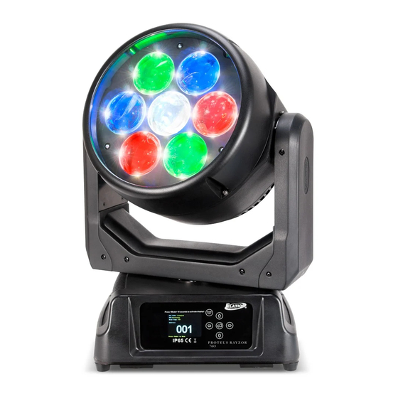
Page 9: Overview
O V E R V I E W 1. Lens 2. System Menu LCD Display 3. Mode/Esc Button 4. Left Button 5. Enter Button 6. Down Button 7. Right Button 8. Up Button 9. Pan Lock 10. Carrying Handle(s) 11. 5-pin DMX Output 12. -
Page 10: Installation Guidelines
I N S TA L L AT I O N G U I D E L I N E S FLAMMABLE MATERIAL WARNING Keep fixture minimum 5.0 feet (1.5m) away from flammable materials and/or pyro- technics. ELECTRICAL CONNECTIONS A qualified electrician should be used for all electrical connections and/or installa- tions. - Page 11 I N S TA L L AT I O N G U I D E L I N E S OMEGA BRACKET INSTALLATION Insert the Omega Brackets into the matching holes on the bottom of the fixture. Secure the Omega Brackets to the fixture by turning each quick-lock fastener ¼ turn clockwise. Always check to make sure that each fastener is completely locked.
- Page 12 I N S TA L L AT I O N G U I D E L I N E S POWER AND DATA CABLES TO MAINTAIN THE IP65 RATING INTEGRITY OF THE FIXTURE, ALL CABLES MUST BE RUN TOWARDS THE GROUND IN ORDER TO PREVENT WATER ACCUMULATION AROUND THE CONNECTIONS.
- Page 13 I N S TA L L AT I O N G U I D E L I N E S POWER AND DATA CONNECTIONS ENSURE ALL CONNECTIONS AND END CAPS ARE PROPERLY SEALED WITH A DIELECTRIC GREASE (AVAILABLE AT MOST ELECTRICAL SUPPLIERS) IN ORDER TO PREVENT WATER CORROSION AND/OR ELECTRICAL SHORT CIRCUIT.
- Page 14 I N S TA L L AT I O N G U I D E L I N E S POTENTIAL INTERNAL FIXTURE DAMAGE FROM EXTERNAL SOURCES OF LIGHT BEAMS External sources of light beams from direct sunlight, lighting and moving head fixtures, and lasers, which are focused directly towards the exterior housing and/or penetrate the front lens opening of ADJ lighting fixtures, can cause severe internal damage including burning of optics, dichroic color filters, glass and metal gobos, prisms, animation wheels, frost filters,...
-
Page 15: Torque Settings For Screws
T O R Q U E S E T T I N G S F O R S C R E W S PANEL SCREWS MUST BE TIGHTENED WITH A TORQUE WRENCH ACCORDING TO THE TORQUE SPECIFICATION DESCRIBED BELOW. The hex-head screws holding the panels MUST be tightened with a torque wrench. (not included). - Page 16 CAUTION! DO NOT OVER TORQUE SCREWS AS THIS CAN CAUSE LEAKAGE ISSUES! TO CONFIRM THE IP65 INTEGRITY AFTER A LAMP REPLACEMENT, TEST THE FIXTURE USING THE IP TESTER. CONTACT ELATION SERVICE FOR MORE DETAILS. CAUTION! THE USE OF PROTECTIVE GLOVES AND SAFETY GOGGLES IS...
-
Page 17: Remote Device Management (Rdm)
R E M O T E D E V I C E M A N A G E M E N T ( R D M ) NOTE: In order for RDM to work properly, RDM enabled equipment must be used through- out the entire system, including DMX data splitters and wireless systems. -
Page 18: System Menu
To activate the display on battery power, press and hold the MODE button for 3 sec- onds. ALTHOUGH E-FLY SETTINGS MAY APPEAR IN THE SYSTEM MENU, THIS FEATURE IS NOT ACTIVATED. E-FLY WIRELESS DMX IS AN OPTIONAL FEATURE WHICH MUST BE ACTIVATED IN THE SERVICE MENU. PLEASE CONTACT ELATION SERVICE FOR FURTHER DETAILS. - Page 19 S Y S T E M M E N U ELATION PROTEUS RAYZOR 1960 SYSTEM MENU Supports Software Versions: 1.2.1 Features subject to change without notice. Rotation direction (clockwise/counter-clockwise) and control of effects depend on head orientation and pan/tilt settings.
- Page 20 S Y S T E M M E N U Address via DMX On / Off Close No DMX Status Hold Auto Pan Reverse On / Off Tilt Reverse On / Off Status Settings Pan Degree 360 / 540 Tilt Degree 360 / 270 Shortest Path Pan Tilt Path...
- Page 21 S Y S T E M M E N U Linear Square Dimmer Curve PERSONALITY Inverse Square (continued) S-Curve Reset Default On / Off Passcode = 011 Restore to factory settings Reset All RESET Reset Pan & Tilt FUNCTION Reset Others Test Channel Pan...
- Page 22 S Y S T E M M E N U REVISED SUB MENUS WITH SOFTWARE UPDATE VERSION 1.2.2 See menu items below which have been updated with this software update. MAIN MENU SUB MENU OPTIONS / VALUES DESCRIPTION Standard Stage Set Dimmer Mode Architectural Theatre...
-
Page 23: Record Controller
R E C O R D C O N T R O L L E R WORKING WITH BUILT-IN PROGRAMS A Primary unit can send up to 3 different data groups to the Secondary units. In other words, a Primary unit can operate up to 3 different Secondary units, with each Secondary unit oper- ating a different set of programs. - Page 24 R E C O R D C O N T R O L L E R EXAMPLE: WORKING WITH BUILT-IN PROGRAMS Program 2 includes scenes: 10, 11, 12, & 13 Program 4 includes scenes: 8, 9, & 10 Program 6 includes scenes: 12, 13, 14, & 15 Auto Pro Part 1 is Program 2 Auto Pro Part 2 is Program 3 Auto Pro Part 3 is Program 6...
-
Page 25: Lighting Console Patching Guidelines
L I G H T I N G C O N S O L E P AT C H I N G G U I D E L I N E S The PROTEUS RAYZOR 760 is a versatile luminaire which combines two fixtures into one housing, allowing it to produce multiple unique lighting effects typically not found in a single lighting fixture. - Page 26 L I G H T I N G C O N S O L E P AT C H I N G G U I D E L I N E S PIXEL LAYOUT PIXEL NUMBERS RGBW Row 1 1, 2 RGBW Row 2 3, 4, 5 RGBW Row 3...
- Page 27 L I G H T I N G C O N S O L E P AT C H I N G G U I D E L I N E S There are also two additional parts for a primary control of the PROTEUS RAYZOR 760, which creates four separate control areas for the fixture.
- Page 28 L I G H T I N G C O N S O L E P AT C H I N G G U I D E L I N E S ONYX screen shots below illustrate Main and Sub Fixture ID patch for a single PROTEUS RAYZOR 760 fixture.
- Page 29 L I G H T I N G C O N S O L E P AT C H I N G G U I D E L I N E S ONYX groups example below for easier selection of a single PROTEUS RAYZOR 760 fixture. Group Name...
-
Page 30: Dmx Traits
D M X T R A I T S ELATION PROTEUS RAYZOR 760 DMX Channel Traits Supports Software Versions: 1.2.1 Features subject to change without notice. Rotation direction (clockwise/counter-clockwise) and control of effects depends on head orientation and pan/tilt settings. - Page 31 D M X T R A I T S CHANNEL FADE FUNCTION FAULT VALUES STATUS STANDARD PIXELS EXTENDED SPARK LED VALUE Color Wheel (continued) 050 - 054 Teal 055 - 059 Cyan 060 - 064 Light Blue 065 - 069 Aqua 070 - 074 Dark Aqua 075 - 079 Green Blue 080 - 084 Light Lavender...
- Page 32 D M X T R A I T S CHANNEL FADE FUNCTION FAULT VALUES STATUS STANDARD PIXELS EXTENDED SPARK LED VALUE Strobe 000 - 031 Shutter Closed 032 - 063 Shutter Open 064 - 095 Strobe, slow to fast 096 - 127 Fast Close, Slow Open Snap 128 - 159 Fast Open, Slow Close 160 - 191 Pulse Effects...
- Page 33 D M X T R A I T S CHANNEL FADE FUNCTION FAULT VALUES STATUS STANDARD PIXELS EXTENDED SPARK LED VALUE Dimmer Delay Time (con- tinued) 9.0 s Snap 10.0 s 142 - 255 Idle Zoom 000 - 215 Zoom, wide to narrow Fade Overdrive, minimum to 215 - 255...
- Page 34 D M X T R A I T S CHANNEL FADE FUNCTION FAULT VALUES STATUS STANDARD PIXELS EXTENDED SPARK LED VALUE Refresh Rate (Hz) (contin- ued) 1000 1010 1020 1030 1040 1050 1060 1070 1080 1090 1100 1110 1120 1130 1140 1150 1160...
- Page 35 D M X T R A I T S CHANNEL FADE FUNCTION FAULT VALUES STATUS STANDARD PIXELS EXTENDED SPARK LED VALUE Refresh Rate (Hz) (contin- ued) 1370 1380 1390 1400 1410 1420 1430 1440 1450 1460 1470 1480 1490 1500 2500 4000 5000...
- Page 36 D M X T R A I T S CHANNEL FADE FUNCTION FAULT VALUES STATUS STANDARD PIXELS EXTENDED SPARK LED VALUE RGBW FX Table, FX selec- tion 1 - 255 (see RGBW 000 - 255 Snap FX Table section of this manual) RGBW FX Speed 000 - 126 Rev fast to slow...
- Page 37 D M X T R A I T S CHANNEL FADE FUNCTION FAULT VALUES STATUS STANDARD PIXELS EXTENDED SPARK LED VALUE 000 - 255 Green 5, 0% to 100% Fade 000 - 255 Blue 5, 0% to 100% Fade 000 - 255 White 5, 0% to 100% Fade 000 - 255 Red 6, 0% to 100% Fade...
- Page 38 D M X T R A I T S CHANNEL FADE FUNCTION FAULT VALUES STATUS STANDARD PIXELS EXTENDED SPARK LED VALUE Spark LED #8 Dimmer, 0% 000 - 255 Fade to 100% Spark LED #9 Dimmer, 0% 000 - 255 Fade to 100% Spark LED #10 Dimmer,...
-
Page 39: Color Temperature Control Table
C O L O R T E M P E R AT U R E C O N T R O L TA B L E COLOR TEMP DMX VALUE COLOR TEMP DMX VALUE 2000 4150 2050 4200 2100 4250 2150 4300 2200... - Page 40 C O L O R T E M P E R AT U R E C O N T R O L TA B L E COLOR TEMP DMX VALUE COLOR TEMP DMX VALUE 6300 8450 6350 8500 6400 8550 6450 8600 6500...
-
Page 41: Fx Generator Guidelines
F X G E N E R AT O R G U I D E L I N E S Selection and control of the integrated FX on the PROTUES RAYZOR 760 is found in the Main Fixture section. All FX are available even in the smallest DMX control modes. (see below) DMX VALUES FUNCTION 000 - 255... - Page 42 To reshuffle the randomization, set the channel to Idle and reselect the desired random op- tion. The FX system of the PROTEUS RAYZOR 760 allows many different combinations by changing the curves, offsets and speed parameters. The RGBW and SparkLED systems are separate, and...
-
Page 43: Rgbw Fx Table
R G B W F X TA B L E TYPE SLOT NAME FX ADJUSTMENT VALUES Sinewave (default) Step Sawtooth Ramp Up Waveform Ramp Down 6-10 006 - 010 No Function REVISED WITH SOFTWARE UPDATE VERSION 1.2.2 Sinewave Cross (default) Sinewave Full CONTINUED ON NEXT PAGE... - Page 44 R G B W F X TA B L E TYPE SLOT NAME FX ADJUSTMENT VALUES REVISED WITH SOFTWARE UPDATE VERSION 1.2.2 Sawtooth Cross Sawtooth Full Ramp Up Waveform (continued) Ramp Down Step 8-10 008 - 010 No Function Single Reverse, Stop, Forward Single Bounce Reverse, Stop, Forward...
- Page 45 R G B W F X TA B L E TYPE SLOT NAME FX ADJUSTMENT VALUES >< Reverse, Stop, Forward >> Reverse, Stop, Forward << Reverse, Stop, Forward Rotating Bar Reverse, Stop, Forward Rotating Dot Reverse, Stop, Forward Rotating 2 Dot Reverse, Stop, Forward Ring 2 Cell Reverse, Stop, Forward...
- Page 46 R G B W F X TA B L E TYPE SLOT NAME FX ADJUSTMENT VALUES REVISED WITH SOFTWARE UPDATE VERSION 1.2.2 Center Chase Reverse, Stop, Forward Center Chase 2 Reverse, Stop, Forward Alternate Reverse, Stop, Forward Intensity Burst Spark LED Reverse, Stop, Forward (continued) Burst RGBW...
- Page 47 R G B W P I X E L F X TA B L E TYPE SLOT NAME FX ADJUSTMENT VALUES REVISED WITH SOFTWARE UPDATE VERSION 1.2.2 RGBW Single Columns Reverse, Stop, Forward RGBWCMY Single Col- Reverse, Stop, Forward umns Color Wheel Single Col- Reverse, Stop, Forward umns...
-
Page 48: Spark Led Fx Table
S P A R K L E D F X TA B L E TYPE SLOT NAME FX ADJUSTMENT VALUES Sinewave (default) Step Sawtooth Ramp Up Waveform Ramp Down 6-10 006 - 010 No Function REVISED WITH SOFTWARE UPDATE VERSION 1.1.1 Sinewave Cross (default) Sinewave Full CONTINUED ON NEXT PAGE... - Page 49 S P A R K L E D F X TA B L E TYPE SLOT NAME FX ADJUSTMENT VALUES Waveform REVISED WITH SOFTWARE UPDATE VERSION 1.1.1 (continued) Sawtooth Cross Sawtooth Full Ramp Up Ramp Down Step 8-10 008 - 010 No Function Starfield Reverse, Stop, Forward 1 Pixel...
- Page 50 S P A R K L E D F X TA B L E TYPE SLOT NAME FX ADJUSTMENT VALUES Pixel Ring Chase Reverse, Stop, Forward Pixel Row Chase Reverse, Stop, Forward Pixel Ring Chase 2 Reverse, Stop, Forward Center Out Reverse, Stop, Forward Spark LED FX Fireworks...
- Page 51 S P A R K L E D F X TA B L E TYPE SLOT NAME FX ADJUSTMENT VALUES Arrow Right Reverse, Stop, Forward 2 Pixels Reverse, Stop, Forward 3 Pixels Reverse, Stop, Forward 4 Pixels Reverse, Stop, Forward 1, 2, 3, 4 Pixels Reverse, Stop, Forward Ring Build...
- Page 52 S P A R K L E D F X TA B L E TYPE SLOT NAME FX ADJUSTMENT VALUES Row 1 Disabled Row 2 Disabled Row 3 Disabled Row 4 Disabled Row 5 Disabled Row 6 Disabled Row 7 Disabled Column 1 Disabled...
-
Page 53: Error Codes
E R R O R C O D E S When power is applied, the unit will automatically enter a “Reset/Test” mode, which brings all the internal motors to a home position. If there is an internal problem with one or more of the motors, an error code will flash on the display screen. -
Page 54: Specifications
S P E C I F I C AT I O N S SOURCE (7) 60W Osram RGBW LEDs (28) 2W White SparkLED™ 50,000 Hour Average LED Life* *Test lab conditions. May vary depending on several factors including but not limited to: Environmental Conditions, Power/Voltage, Usage Patterns (On-Off Cycling), Control, and Dimming. -
Page 55: Dimensional Drawings
D I M E N S I O N A L D R A W I N G S 237mm(9.33in ) 363.4mm(14.31in Press <Mode> 10 seconds to activate display! MOD E / E S C P R OTE U S R AYZ OR 76 0 352.04mm(13.86in 259.97mm(10.24in 128.98mm(5.08in) -
Page 56: Optional Accessories | Fcc Statement
O P T I O N A L A C C E S S O R I E S ORDER CODE ITEM IP TESTER IP Fixture Vacuum and Pressure Leak Tester TRIGGER CAMP Heavy Duty Wrap Around Hook Style Clamp 5 ft (1.5m) IP65 5-pin XLR Cable STR527 (additional cable lengths are available)
Need help?
Do you have a question about the PROTEUS RAYZOR 760 and is the answer not in the manual?
Questions and answers