Table of Contents
Advertisement
Advertisement
Table of Contents

Related Manuals for Elation PROTRON ECLYPSE


Summary of Contents for Elation PROTRON ECLYPSE
- Page 1 user manual...
- Page 2 +31 45 546 85 66 | +31 45 546 85 96 fax | www.elationlighting.eu | info@elationlighting.eu Elation Professional Mexico | AV Santa Ana 30 | Parque Industrial Lerma, Lerma, Mexico 52000 +52 (728) 282-7070 D O C U M E N T V E R S I O N Due to additional product features and/or enhancements, an updated version of this document may be available online.
-
Page 3: Table Of Contents
C O N T E N T S General Information Limited Warranty (USA Only) Safety Guidelines Maintenance Guidelines Fixture Overview Installation Guidelines System Menu Pixel Zone Control DMX Channel Functions and Values Specifications Optional Accessories... -
Page 4: General Information
BOX CONTENTS (1) Omega Bracket (1) Seetronic IP65 Power Cable CUSTOMER SUPPORT Contact ELATION Service for any product related service and support needs. Also visit forums.elationlighting.com with questions, comments or suggestions. ELATION SERVICE USA - Monday - Friday 8:00am to 4:30pm PST 323-582-3322 | Fax 323-832-9142 | support@elationlighting.com... -
Page 5: Limited Warranty (Usa Only)
No accessories should be shipped with the product. If any accessories are shipped with the product, Elation Professional shall have no liability what so ever for loss and/or or damage to any such accessories, nor for the safe return thereof. C. This warranty is void if the product serial number and/or labels are altered or removed;... -
Page 6: Safety Guidelines
This fixture is a sophisticated piece of electronic equipment. To guarantee a smooth operation, it is important to follow all instructions and guidelines in this manual. Elation Professional is not responsible for injury and/or damages resulting from the misuse of this fixture due to the disregard of the information printed in this manual. - Page 7 S A F E T Y G U I D E L I N E S DO NOT TOUCH the fixture housing during operation. Turn OFF the power and allow approximately 15 minutes for the fixture to cool down before serving. DO NOT shake fixture, avoid brute force when installing and/or operating fixture.
-
Page 8: Maintenance Guidelines
Regular inspections are recommended to insure proper function and extended life. There are no user serviceable parts inside this fixture, please refer all other service issues to an authorized Elation service technician. Should you need any spare parts, please order genuine parts from your local Elation dealer. -
Page 9: Fixture Overview
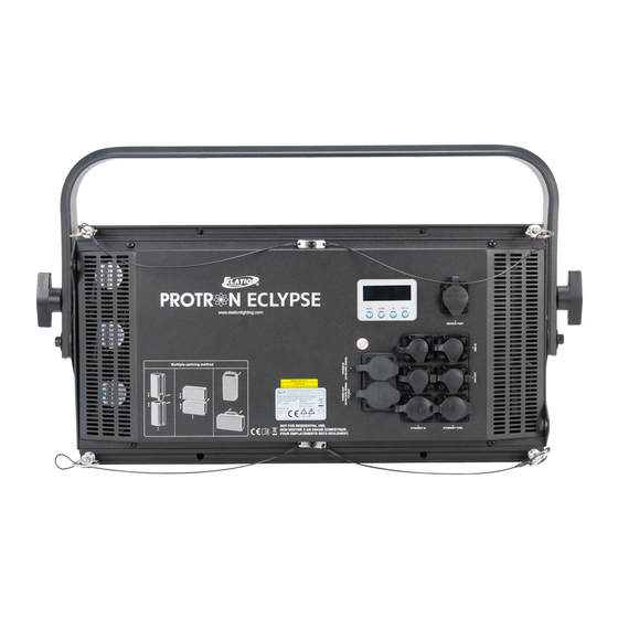
F I X T U R E O V E R V I E W 1. OLED Control Menu Display 2. MENU, DOWN, UP, ENTER Buttons 3. PowerKON IP65 Power IN/OUT 4. Ethernet RJ45 IN/OUT 5. 3pin/5pin DMX IN/OUT... -
Page 10: Installation Guidelines
I N S T A L L A T I O N G U I D E L I N E S IPX4 RATED An IP rated lighting fixture is one, which is commonly installed in outdoor environments and has been designed with an enclosure that effectively protects the ingress (entry) of external foreign objects such as dust and water. - Page 11 I N S T A L L A T I O N G U I D E L I N E S DO NOT INSTALL THE FIXTURE IF YOU ARE NOT QUALIFIED TO DO SO! Fixture MUST be installed following all local, national, and country commercial electrical and construction codes and regulations.
- Page 12 I N S T A L L A T I O N G U I D E L I N E S CLAMP MOUNTING The adjustable yoke bracket attached to the fixture includes 3-position holes for versatile fixture positioning. Depending on rigging position of the fixture, it may be best to use more than one clamp attached to the yoke.
- Page 13 I N S T A L L A T I O N G U I D E L I N E S LINKING FIXTURES The fixture includes integrated spring-loaded locking pins which are used to connect multiple fixtures together horizontally and vertically to create seamless custom matrix designs.
- Page 14 I N S T A L L A T I O N G U I D E L I N E S Horizontal Fixture Linking 1. Remove spring-loaded locking-pin, compress the spring enough to clear the rail, rotate ring to vertical orientation (stepped rail-block to a horizontal orientation), and pull it straight out.
- Page 15 I N S T A L L A T I O N G U I D E L I N E S Horizontal Fixture Linking 4. With both fixtures horizontally adjoined, align the locking-pin rail holes with the holes in the locking-pin abutment-block, and insert one locking-pin into the first set of aligned holes.
- Page 16 I N S T A L L A T I O N G U I D E L I N E S Vertical Fixture Linking 1. To vertically secure two fixtures, each fixture has integrated locking-pin rails at the top and bottom. With both fixtures vertically aligned, the bottom rail straddles the top rail of the bottom unit.
- Page 17 I N S T A L L A T I O N G U I D E L I N E S MAXIMUM 5 FIXTURES CAN BE SAFELY LINKED VERTICALLY OR HORIZONTALLY! NOTE: Illustration below shows optional bracket and clamp. (not included) EACH FIXTURE MUST BE SECURED WITH ITS OWN SAFETY CABLE! USE AN APPROPRIATELY RATED SAFETY CABLE (NOT INCLUDED) THAT MEETS ALL LOCAL, NATIONAL, AND COUNTRY CODES AND REGULATIONS.
-
Page 18: System Menu
S Y S T E M M E N U The fixture includes an easy to navigate system menu where fixture settings can be adjusted via the LCD control panel located on the back of the fixture. (see image below) During normal operation, pressing the MODE button once will access the main menu. - Page 19 S Y S T E M M E N U Supports Software Versions: ≥ A1.1 B1.1 Features are subject to change without any prior written notice. MENU SUB MENU OPTIONS / VALUES DESCRIPTION (Default Settings in BOLD) DMX Address 001 ~ xxx DMX Address Setting IP Address (xxx.xxx.xxx.xxx) Enter Fixture IP Address...
-
Page 20: Pixel Zone Control
P I X E L Z O N E C O N T R O L Pixel zones can be changed by selecting different Channel Modes in the system menu. See diagrams below for which pixel zone corresponds to each Channel Mode. -
Page 21: Dmx Channel Functions And Values
D M X C H A N N E L F U N C T I O N S A N D V A L U E S ELATION PROTRON ECLYPSE™ | DMX Channel Values / Functions (57 DMX Channels) Supports Software Versions: ≥... - Page 22 MODE / CHANNEL VALUE FUNCTION RGBW RGBW Strobe 16 bit 16 bit RED 1 (0-100%) 0-255 GREEN 1 (0-100%) 0-255 BLUE 1 (0-100%) 0-255 WHITE 1 (0-100%) 0-255 RED 2 (0-100%) 0-255 GREEN 2 (0-100%) 0-255 BLUE 2 (0-100%) 0-255 WHITE 2 (0-100%) 0-255...
- Page 23 MODE / CHANNEL VALUE FUNCTION RGBW RGBW Strobe 16 bit 16 bit RED 7 (0-100%) 0-255 GREEN 7 (0-100%) 0-255 BLUE 7 (0-100%) 0-255 WHITE 7 (0-100%) 0-255 RED 8 (0-100%) 0-255 GREEN 8 (0-100%) 0-255 BLUE 8 (0-100%) 0-255 WHITE 8 (0-100%) 0-255...
-
Page 24: Specifications
S P E C I F I C A T I O N S SOURCE 96 10W CREE RGBW 4-in-1LEDs 15,000 Hour Average LED Life* *May vary depending on several factors including but not limited to: Environmental Conditions, Power/Voltage, Usage Patterns (On-Off Cycling), Control, and Dimming. EFFECTS Color Blinder, Strobe, and Wash Brilliant Eye Candy Effects... - Page 25 DIMENSIONAL DRAWINGS Specifications and improvements in the design of this unit and this manual are subject to change without any prior written notice.
-
Page 26: Optional Accessories
O P T I O N A L A C C E S S O R I E S ORDER CODE ITEM TRIGGER CLAMP Heavy Duty Wrap Around Hook Style Clamp SCABLE60 Safety Cable 24” (610mm) 60 lbs. (27kg) Rating STR527 5 ft. - Page 27 FCC STATEMENT This device complies with Part 15 of the FCC Rules. Operation is subject to the following two conditions: (1) this device may not cause harmful interference, and (2) this device must accept any interference received, including interference that may cause undesired operation. FCC RADIO FREQUENCY INTERFERENCE WARNINGS &...
Need help?
Do you have a question about the PROTRON ECLYPSE and is the answer not in the manual?
Questions and answers