Table of Contents
Advertisement
Quick Links
Advertisement
Table of Contents

Related Manuals for Elation PROTEUS RAYZOR 760 WMG


Summary of Contents for Elation PROTEUS RAYZOR 760 WMG
- Page 1 P ROT EUS RAYZ O R 76 0 / RAYZ O R 76 0 WMG user manual...
- Page 2 Elation Professional B.V. | Junostraat 2 | 6468 EW Kerkrade, The Netherlands +31 45 546 85 66 | +31 45 546 85 96 fax | www.elationlighting.eu | info@elationlighting.eu Elation Professional Mexico | AV Santa Ana 30 | Parque Industrial Lerma, Lerma, Mexico 52000 +52 (728) 282-7070...
-
Page 3: Table Of Contents
C O N T E N T S Introduction IP65 Limited Warranty (USA Only) Safety Guidelines Maintenance Guidelines Overview Installation Guidelines Torque Settings for Screws Remote Device Management (RDM) System Menu Record Controller Lighting Console Patching Guidelines DMX Traits Color Temperature Control Table FX Generator Guidelines RGBW FX Table Error Codes... - Page 4 IP65 Rated 5-pin DMX Cable (x1) IP65 Rated RJ45 Data Cable (x1) - FIXTURE TO FIXTURE INTERCONNECTION USE ONLY! IP65 Locking Power Cable (x1) CUSTOMER SUPPORT Contact ELATION Service for any product related service and support needs. Also visit forums.elationlighting.com with questions, comments or suggestions.
-
Page 5: Ip65
I P 6 5 R AT E D The International Protection (IP) rating system is commonly expressed as “IP” (Ingress Protection) followed by two numbers (i.e. IP65), where the numbers define the degree of protection. The first digit (Foreign Bodies Protection) indicates the extent of protection against particles entering the fixture, and the second digit (Water Protection) indicates the extent of protection against water entering the fixture. -
Page 6: Limited Warranty (Usa Only)
It is the owner’s responsibility to establish the date and place of purchase by acceptable evidence, at the time service is sought. B. For warranty service, send the product only to the Elation Professional factory. All shipping charges must be pre-paid. If the requested repairs or service (including parts replacement) are within the terms of this warranty, Elation Professional will pay return shipping charges only to a designated point within the United States. -
Page 7: Safety Guidelines
This fixture is a sophisticated piece of electronic equipment. To guarantee a smooth operation, it is important to follow all instructions and guidelines in this manual. Elation Professional is not responsible for injury and/or damages resulting from the misuse of this fixture due to the disregard of the information printed in this manual. - Page 8 S A F E T Y P R E C A U T I O N S • DO NOT TOUCH the fixture housing during operation. Turn OFF the power and allow approximately 15 minutes for the fixture to cool down before servicing. •...
-
Page 9: Maintenance Guidelines
Regular inspections are recommended to ensure proper function and extended life. There are no user serviceable parts inside this fixture. Please refer all other service issues to an authorized Elation service technician. Should you need any spare parts, please order genuine parts from your local Elation dealer. -
Page 10: Overview
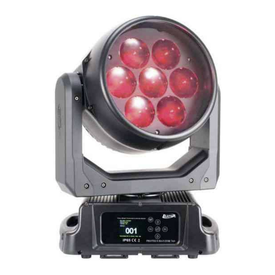
O V E R V I E W 1. Lens 2. System Menu LCD Display 3. Mode/Esc Button 4. Left Button 5. Enter Button 6. Down Button 7. Right Button 8. Up Button 9. Pan Lock 10. Carrying Handle(s) 11. 5-pin DMX Output 12. -
Page 11: Installation Guidelines
INSTALLATION GUIDELINES FLAMMABLE MATERIAL WARNING Keep fixture minimum 5.0 feet (1.5m) away from flammable materials and/or pyrotechnics. ELECTRICAL CONNECTIONS A qualified electrician should be used for all electrical connections and/or installations. MINIMUM DISTANCE TO SURFACES/OBJECTS IS 3.3 FEET (1 METER). MINIMUM DISTANCE TO FLAMMABLE MATERIALS IS 1.6 FEET (0.5 METER). - Page 12 I N S TA L L AT I O N G U I D E L I N E S OMEGA BRACKET INSTALLATION Insert the Omega Brackets into the matching holes on the bottom of the fixture. Secure the Omega Brackets to the fixture by turning each quick-lock fastener ¼ turn clockwise. Always check to make sure that each fastener is completely locked.
- Page 13 I N S TA L L AT I O N G U I D E L I N E S POWER AND DATA CABLES TO MAINTAIN THE IP65 RATING INTEGRITY OF THE FIXTURE, ALL CABLES MUST BE RUN TOWARDS THE GROUND IN ORDER TO PREVENT WATER ACCUMULATION AROUND THE CONNECTIONS.
- Page 14 I N S TA L L AT I O N G U I D E L I N E S POWER AND DATA CONNECTIONS ENSURE ALL CONNECTIONS AND END CAPS ARE PROPERLY SEALED WITH A DIELECTRIC GREASE (AVAILABLE AT MOST ELECTRICAL SUPPLIERS) IN ORDER TO PREVENT WATER CORROSION AND/OR ELECTRICAL SHORT CIRCUIT.
- Page 15 LEDs. This issue is not specific only to Elation lighting fixtures, but rather it is a common issue with lighting fixtures from all manufacturers. Although there is no true way to fully prevent this issue from happening, the guidelines below can reduce the risk of potential damage.
-
Page 16: Torque Settings For Screws
ISSUES! TO CONFIRM THE IP65 INTEGRITY AFTER A PROCEDURE REQUIRING DISASSEMBLY/REASSEMBLY, TEST THE FIXTURE USING THE IP TESTER. CONTACT ELATION SERVICE FOR MORE DETAILS. CAUTION! THE USE OF PROTECTIVE GLOVES AND SAFETY GOGGLES IS STRONGLY RECOMMENDED WHILE PERFORMING THE IP PRESSURE TEST! AVOID PLACING YOUR FACE, EYES, HANDS, ETC IN CLOSE PROXIMITY TO THE FIXTURE’S LENS... - Page 17 ISSUES! TO CONFIRM THE IP65 INTEGRITY AFTER A PROCEDURE REQUIRING DISASSEMBLY/REASSEMBLY, TEST THE FIXTURE USING THE IP TESTER. CONTACT ELATION SERVICE FOR MORE DETAILS. CAUTION! THE USE OF PROTECTIVE GLOVES AND SAFETY GOGGLES IS STRONGLY RECOMMENDED WHILE PERFORMING THE IP PRESSURE TEST! AVOID PLACING YOUR FACE, EYES, HANDS, ETC IN CLOSE PROXIMITY TO THE FIXTURE’S LENS...
-
Page 18: Remote Device Management (Rdm)
R E M O T E D E V I C E M A N A G E M E N T ( R D M ) NOTE: In order for RDM to work properly, RDM enabled equipment must be used throughout the entire system, including DMX data splitters and wireless systems. -
Page 19: System Menu
MODE button for 3 seconds. ALTHOUGH E-FLY SETTINGS MAY APPEAR IN THE SYSTEM MENU, THIS FEATURE IS NOT ACTIVATED. E-FLY WIRELESS DMX IS AN OPTIONAL FEATURE WHICH MUST BE ACTIVATED IN THE SERVICE MENU. PLEASE CONTACT ELATION SERVICE FOR FURTHER DETAILS. - Page 20 S YS T E M M E N U ( V 1 . 2 . 1 ) Supports Software Versions: 1.2.1 Features subject to change without notice. Rotation direction (clockwise/counter-clockwise) and control of effects depend on head orientation and pan/tilt settings.
- Page 21 S YS T E M M E N U ( V 1 . 2 . 1 ) Supports Software Versions: 1.2.1 MAIN MENU SUB MENU OPTIONS / VALUES DESCRIPTION Address via DMX On / Off Close No DMX Status Hold Auto Pan Reverse On / Off...
- Page 22 S YS T E M M E N U ( V 1 . 2 . 1 ) Supports Software Versions: 1.2.1 MAIN MENU SUB MENU OPTIONS / VALUES DESCRIPTION Reset All RESET Reset Pan & Tilt FUNCTION Reset Others Test Channel Pan...
- Page 23 S YS T E M M E N U ( V 1 . 2 . 2 ) REVISED SUB MENUS WITH SOFTWARE UPDATE VERSION 1.2.2 MAIN MENU SUB MENU OPTIONS / VALUES DESCRIPTION Standard Stage Set Dimmer Mode Architectural Theatre Stage 2 0.0 s 0.1 s...
- Page 24 S YS T E M M E N U ( V 1 . 3 ) REVISED SUB MENUS WITH SOFTWARE UPDATE VERSION 1.3 MAIN MENU SUB MENU OPTIONS / VALUES DESCRIPTION Address Via DMX On / Off Set Dimmer Mode Close Hold No DMX Status...
- Page 25 S YS T E M M E N U ( V 1 . 3 . 3 ) Supports Software Version 1.3.3 MAIN MENU SUB MENU OPTIONS / VALUES DESCRIPTION Set DMX Address A001 - Axxx Set DMX address DMX Value All...
- Page 26 S YS T E M M E N U ( V 1 . 3 . 3 ) Supports Software Version 1.3.3 MAIN MENU SUB MENU OPTIONS / VALUES DESCRIPTION Address via DMX On / Off Close Hold No DMX Status Auto Sun Prot Pan Reverse...
- Page 27 S YS T E M M E N U ( V 1 . 3 . 3 ) Supports Software Version 1.3.3 MAIN MENU SUB MENU OPTIONS / VALUES DESCRIPTION Linear Square Dimmer Curve PERSONALITY Inverse Square S-Curve Reset Default On / Off Passcode = 011 Restore to factory settings Reset All...
- Page 28 R E C O R D C O N T R O L L E R WORKING WITH BUILT-IN PROGRAMS A Primary unit can send up to 3 different data groups to the Secondary units. In other words, a Primary unit can operate up to 3 different Secondary units, with each Secondary unit operating a different set of programs.
- Page 29 R E C O R D C O N T R O L L E R EXAMPLE: WORKING WITH BUILT-IN PROGRAMS Program 2 includes scenes: 10, 11, 12, & 13 Program 4 includes scenes: 8, 9, & 10 Program 6 includes scenes: 12, 13, 14, & 15 Auto Pro Part 1 is Program 2 Auto Pro Part 2 is Program 3 Auto Pro Part 3 is Program 6...
- Page 30 L I G H T I N G C O N S O L E PAT C H I N G G U I D E L I N E S The PROTEUS RAYZOR 760 is a versatile luminaire which combines two fixtures into one housing, allowing it to produce multiple unique lighting effects typically not found in a single lighting fixture.
- Page 31 L I G H T I N G C O N S O L E PAT C H I N G G U I D E L I N E S PIXEL LAYOUT PIXEL NUMBERS RGBW Row 1 1, 2 RGBW Row 2 3, 4, 5 RGBW Row 3...
- Page 32 L I G H T I N G C O N S O L E PAT C H I N G G U I D E L I N E S There are also two additional parts for a primary control of the PROTEUS RAYZOR 760, which creates four separate control areas for the fixture.
- Page 33 L I G H T I N G C O N S O L E PAT C H I N G G U I D E L I N E S ONYX screen shots below illustrate Main and Sub Fixture ID patch for a single PROTEUS RAYZOR 760 fixture.
- Page 34 L I G H T I N G C O N S O L E PAT C H I N G G U I D E L I N E S ONYX groups example below for easier selection of a single PROTEUS RAYZOR 760 fixture. Group Name Group Content All RGBW Pixels Main...
- Page 35 D M X T R A I T S : M A I N F I X T U R E C O N T R O L ( V 1 . 2 . 1 ) Features subject to change without notice. Rotation direction (clockwise/counter-clockwise) and control of effects depends on head orientation and pan/tilt settings.
- Page 36 D M X T R A I T S : M A I N F I X T U R E C O N T R O L CHANNEL FADE DEFAULT FUNCTION VALUES STATUS VALUE STANDARD PIXELS EXTENDED SPARK LED Color Scroll 180 - 201 Clockwise, fast to slow 202 - 207 Stop...
- Page 37 D M X T R A I T S : M A I N F I X T U R E C O N T R O L CHANNEL FADE DEFAULT FUNCTION STANDARD PIXELS EXTENDED SPARK LED VALUES STATUS VALUE Zoom 000 - 215 Zoom, wide to narrow Fade...
- Page 38 D M X T R A I T S : M A I N F I X T U R E C O N T R O L CHANNEL FADE DEFAULT FUNCTION STANDARD PIXELS EXTENDED SPARK LED VALUES STATUS VALUE Refresh Rate (Hz) (continued) 1210 1220...
- Page 39 D M X T R A I T S : M A I N F I X T U R E C O N T R O L CHANNEL FADE DEFAULT FUNCTION STANDARD PIXELS EXTENDED SPARK LED VALUES STATUS VALUE RGBW FX Table, FX selection 1 - 000 - 255 255 (see RGBW FX Table section...
- Page 40 D M X T R A I T S : S PA R K L E D C O N T R O L NOTE: Spark LED is not available as a mode in the fixture menu, but must be provided as a console control profile for easy programming of the fixture.
- Page 41 C O LO R T E M P E R AT U R E C O N T R O L TA B L E COLOR COLOR COLOR COLOR TEMP VALUE TEMP VALUE TEMP VALUE TEMP VALUE 2000 4150 6300 8450 2050 4200...
- Page 42 F X G E N E R AT O R G U I D E L I N E S Selection and control of the integrated FX on the PROTUES RAYZOR 760 is found in the Main Fixture section. All FX are available even in the smallest DMX control modes. DMX VALUES FUNCTION 000 - 255...
- Page 43 F X G E N E R AT O R G U I D E L I N E S In addition to FX direction and speed control, a Sync channel allows to offset or randomize the fixtures or the FX steps. DMX VALUES FUNCTION FX Offset...
- Page 44 R G B W F X TA B L E TYPE SLOT NAME FX ADJUSTMENT VALUES Sinewave (default) Step Sawtooth Ramp Up Waveform Ramp Down 6-10 006 - 010 No Function REVISED WITH SOFTWARE UPDATE VERSION 1.2.2 Sinewave Cross (default) Sinewave Full...
- Page 45 R G B W F X TA B L E TYPE SLOT NAME FX ADJUSTMENT VALUES REVISED WITH SOFTWARE UPDATE VERSION 1.2.2 Sawtooth Cross Sawtooth Full Ramp Up Waveform Ramp Down Step 8-10 008 - 010 No Function Single Reverse, Stop, Forward Single Bounce Reverse, Stop, Forward Snake...
- Page 46 R G B W F X TA B L E TYPE SLOT NAME FX ADJUSTMENT VALUES >< Reverse, Stop, Forward >> Reverse, Stop, Forward << Reverse, Stop, Forward Rotating Bar Reverse, Stop, Forward Rotating Dot Reverse, Stop, Forward Rotating 2 Dot Reverse, Stop, Forward Ring 2 Cell Reverse, Stop, Forward...
- Page 47 R G B W F X TA B L E TYPE SLOT NAME FX ADJUSTMENT VALUES REVISED WITH SOFTWARE UPDATE VERSION 1.2.2 Center Chase Reverse, Stop, Forward Center Chase 2 Reverse, Stop, Forward Alternate Reverse, Stop, Forward Intensity Burst Spark LED Reverse, Stop, Forward (continued) Burst RGBW...
- Page 48 R G B W F X TA B L E TYPE SLOT NAME FX ADJUSTMENT VALUES REVISED WITH SOFTWARE UPDATE VERSION 1.2.2 RGBW Single Columns Reverse, Stop, Forward RGBWCMY Single Col- Reverse, Stop, Forward umns Color Wheel Single Col- Reverse, Stop, Forward umns RGB Rows Reverse, Stop, Forward...
- Page 49 R G B W F X TA B L E TYPE SLOT NAME FX ADJUSTMENT VALUES Sinewave (default) Step Sawtooth Ramp Up Waveform Ramp Down 6-10 006 - 010 No Function REVISED WITH SOFTWARE UPDATE VERSION 1.1.1 Sinewave Cross (default) Sinewave Full...
- Page 50 R G B W F X TA B L E TYPE SLOT NAME FX ADJUSTMENT VALUES Waveform REVISED WITH SOFTWARE UPDATE VERSION 1.1.1 (continued) Sawtooth Cross Sawtooth Full Ramp Up Ramp Down Step 8-10 008 - 010 No Function Starfield Reverse, Stop, Forward 1 Pixel Reverse, Stop, Forward...
- Page 51 R G B W F X TA B L E TYPE SLOT NAME FX ADJUSTMENT VALUES Pixel Ring Chase Reverse, Stop, Forward Pixel Row Chase Reverse, Stop, Forward Pixel Ring Chase 2 Reverse, Stop, Forward Center Out Reverse, Stop, Forward Spark LED FX Fireworks Reverse, Stop, Forward...
- Page 52 R G B W F X TA B L E TYPE SLOT NAME FX ADJUSTMENT VALUES Arrow Right Reverse, Stop, Forward 2 Pixels Reverse, Stop, Forward 3 Pixels Reverse, Stop, Forward 4 Pixels Reverse, Stop, Forward 1, 2, 3, 4 Pixels Reverse, Stop, Forward Ring Build Reverse, Stop, Forward...
- Page 53 R G B W F X TA B L E TYPE SLOT NAME FX ADJUSTMENT VALUES Row 1 Disabled Row 2 Disabled Row 3 Disabled Row 4 Disabled Row 5 Disabled Row 6 Disabled Row 7 Disabled Column 1 Disabled Column 2 Disabled Spark LED...
- Page 54 E R R O R C O D E S When power is applied, the unit will automatically enter a “Reset/Test” mode, which brings all the internal motors to a home position. If there is an internal problem with one or more of the motors, an error code will flash on the display screen.
- Page 55 S P E C I F I C AT I O N S SOURCE (7) 60W Osram RGBW LEDs (28) 2W White SparkLED™ 50,000 Hour Average LED Life* *Test lab conditions. May vary depending on several factors including but not limited to: Environmental Conditions, Power/Voltage, Usage Patterns (On-Off Cycling), Control, and Dimming.
- Page 56 D I M E N S I O N A L D R AW I N G S DRAWINGS NOT TO SCALE 16.6in. [421.5mm] 2.0in. [50.8mm] 9.4in. [239.2mm] Ø14.6in. [Ø370.7mm] 13.9in. [352.0mm] 10.2in. [260.0mm] 14.3in. [363.4mm] 7.1in. [180.0mm] 5.1in. [129.0mm] 3.8in.
- Page 57 O P T I O N A L A C C E S S O R I E S ORDER CODE ITEM IP TESTER IP Fixture Vacuum and Pressure Leak Tester TRIGGER CAMP Heavy Duty Wrap Around Hook Style Clamp 5 ft (1.5m) IP65 5-pin XLR Cable STR527 (additional cable lengths are available)
Need help?
Do you have a question about the PROTEUS RAYZOR 760 WMG and is the answer not in the manual?
Questions and answers