Table of Contents
Advertisement
Advertisement
Table of Contents

Related Manuals for Elation Proteus Lucius


Summary of Contents for Elation Proteus Lucius
- Page 1 user manual...
- Page 2 +31 45 546 85 66 | +31 45 546 85 96 fax | www.elationlighting.eu | info@elationlighting.eu Elation Professional Mexico | AV Santa Ana 30 | Parque Industrial Lerma, Lerma, Mexico 52000 +52 (728) 282-7070 D O C U M E N T V E R S I O N Due to additional product features and/or enhancements, an updated version of this document may be available online.
-
Page 3: Table Of Contents
General Information Limited Warranty (USA Only) Safety Guidelines Maintenance Guidelines Fixture Overview Colors and Gobos Custom Gobos Gobo Installation Torque Settings for Screws Installation Guidelines System Menu Dimmer Curve DMX Channel Functions and Values Error Codes Specifications Dimensional Drawings Optional Accessories... -
Page 4: General Information
IP65 Rated RJ45 DATA Cable (Fixture to Fixture Interconnect Use Only!) IP65 Rated Twist-Lock Power Cable CUSTOMER SUPPORT Contact ELATION Service for any product related service and support needs. Also visit forums.elationlighting.com with questions, comments or suggestions. ELATION SERVICE USA - Monday - Friday 8:00am to 4:30pm PST 323-582-3322 | Fax 323-832-9142 | support@elationlighting.com... -
Page 5: Limited Warranty (Usa Only)
(double-box and foam) that provides ample product protection for ground and/or air freight transit, and must be shipped freight pre-paid and insured to ELATION in Los Angeles, CA or an ELATION Authorized Service Center. The RMA number must be clearly written on the outside of the return box, and a brief description of the problem and the RMA number must be documented and included in the box. -
Page 6: Safety Guidelines
This fixture is a sophisticated piece of electronic equipment. To guarantee a smooth operation, it is important to follow all instructions and guidelines in this manual. Elation Professional is not responsible for injury and/or damages resulting from the misuse of this fixture due to the disregard of the information printed in this manual. - Page 7 S A F E T Y G U I D E L I N E S 89.9 lbs. (40.8kg) RISK GROUP 3 - RISK OF EXPOSURE TO ULTRAVIOLET UV RADIATION! FIXTURE EMITS HIGH INTENSITY WAVELENGTH OF ULTRAVIOLET UV LIGHT FROM THE UV COLOR FILTER. WEAR PROPER EYE AND SKIN PROTECTION.
-
Page 8: Maintenance Guidelines
Regular inspections are recommended to insure proper function and extended life. There are no user serviceable parts inside this fixture, please refer all other service issues to an authorized Elation service technician. Should you need any spare parts, please order genuine parts from an authorized Elation dealer. -
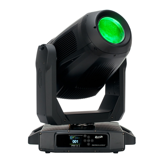
Page 9: Fixture Overview
Le n s U P B utton T il t Lo ck MODE / ESC B utto n EN T ER Bu tto n R IG H T B u tto n LE FT B utto n D OW N Bu tto n LC D Me n u Fun c ti on Di s play PA N Lo c k Car r y i n g H a n dl e (s) -
Page 10: Colors And Gobos
COLORS AND GOBOS COLOR FLAGS CYAN MAGENTA YELLOW C.T.O. COLOR WHEEL GREEN HIGH CRI ORANGE BLUE INTERCHANGEABLE – ROTATING GLASS GOBO WHEEL Pos. 2 Pos. 1 Pos. 3 Pos. 4 Pos. 5 Pos. 6 INTERCHANGEABLE – ROTATING GLASS GOBO WHEEL Pos. -
Page 11: Custom Gobos
Due to varying manufacturing processes and tolerances, it is highly recommended to provide a gobo sample and holder from the fixture to the custom gobo vendor for accurate sizing. Extended testing of custom gobo designs is highly recommended prior to use. Contact ELATION SERVICE for further information. - Page 12 Due to varying manufacturing processes and tolerances, it is highly recommended to provide a gobo sample and holder from the fixture to the custom gobo vendor for accurate sizing. Extended testing of custom gobo designs is highly recommended prior to use. Contact ELATION SERVICE for further information.
- Page 13 Due to varying manufacturing processes and tolerances, it is highly recommended to provide a gobo sample and holder from the fixture to the custom gobo vendor for accurate sizing. Extended testing of custom gobo designs is highly recommended prior to use. Contact ELATION SERVICE for further information.
-
Page 14: Gobo Installation
G O B O I N S T A L L A T I O N REPLACING A ROTATING GOBO Locate the specific Rotating GOBO to replace. Carefully grip the GOBO using your thumb and index GOBO Wheel. finger, gently lift it slightly, and then pull it out and away until it fully clears the Locate the tab of the spring, and with a precision pick (or similar tool), carefully press the retaining spring inward to relieve the tension. -
Page 15: Torque Settings For Screws
* lbf-in = Pound Force Inches | kgf-cm = Kilogram Force Centimeters CAUTION! DO NOT OVER TORQUE SCREWS AS THIS CAN CAUSE LEAKAGE ISSUES! TO CONFIRM THE IP65 INTEGRITY AFTER A LAMP REPLACEMENT, TEST FIXTURE USING THE ELATION IP TESTER. CONTACT ELATION SERVICE FOR MORE DETAILS. -
Page 16: Installation Guidelines
I N S T A L L A T I O N G U I D E L I N E S FLAMMABLE MATERIAL WARNING Keep fixture minimum 5.0 feet (1.5m) away from flammable materials and/or pyrotechnics. ELECTRICAL CONNECTIONS A qualified electrician should be used for all electrical connections and/or installations. USE CAUTION WHEN POWER LINKING OTHER MODEL FIXTURES AS THE POWER CONSUMPTION OF OTHER MODEL FIXTURES MAY EXCEED THE MAX POWER OUTPUT ON THIS FIXTURE. - Page 17 I N S T A L L A T I O N G U I D E L I N E S OMEGA BRACKETS WITH CLAMP INSTALLATION Insert the Omega Brackets into the matching holes on the bottom of the fixture. Secure the Omega Brackets to the fixture by turning each quick-lock fastener ¼...
- Page 18 I N S T A L L A T I O N G U I D E L I N E S CLAMP INSTALLATION Insert (2x) minimum grade 8.8 steel M12x19mm bolts (not included) through the respective mounting hole of the clamp (not included), and then thread it into the matching 12M holes on the bottom of the fixture base.
- Page 19 I N S T A L L A T I O N G U I D E L I N E S RIGGING Overhead rigging requires extensive experience, including among others calculating working load limits, installation material being used, and periodic safety inspection of all installation material and the fixture.
- Page 20 I N S T A L L A T I O N G U I D E L I N E S ART-NET | sACN CONNECTION When connecting fixture to a network switch to control multiple devices, a Gigabit Ethernet Switch that supports IGMP (Internet Group Management Protocol) is required.
- Page 21 I N S T A L L A T I O N G U I D E L I N E S POWER AND DATA CABLES ENSURE ALL CONNECTIONS AND ENDCAPS ARE PROPERLY SEALED WITH DIELECTRIC GREASE (AVAILABLE AT MOST ELECTRICAL SUPPLIERS) TO PREVENT WATER CORROSION AND/OR ELECTRICAL SHORT CIRCUIT.
- Page 22 LEDs. This issue is not specific only to ELATION lighting fixtures, it is a common issue with lighting fixtures from all manufacturers. Although there is no true way to fully prevent this issue from happening, the guidelines below can prevent any potential damage from occurring if followed.
-
Page 23: System Menu
SYSTEM MENU The fixture includes an easy to navigate system menu. The control panel (see image below) located on the front of the fixture, provides access to the main system menu and is where all necessary system adjustments are made to the fixture. During normal operation, pressing MODE/ESC button once will access the fixture’s main menu. - Page 24 S Y S T E M M E N U ELATION PROTEUS LUCIUS ≥ Supports Software Versions: 1.3.0 MAIN MENU OPTIONS / VALUES (Default Settings in BOLD) DESCRIPTION Set Dmx Address A001~AXXX DMX Address Setting Dmx Value PAN…… DMX Value Display...
- Page 25 MAIN MENU OPTIONS / VALUES (Default Settings in BOLD) DESCRIPTION Celsius Te m p e r a t u r e Temp C/F Fahren PAN =XXX Initial Status Initial effect position ..DMX Only Select Signal Art-Net Select Signal sACN Ethernet IP XXX.
- Page 26 S Y S T E M M E N U FUNCTION - Auto Program Define fixture mode (Primary or Alone) for running Auto Programs. Select desired internal programs under “Select Program”, set the number of steps under “Edit program”, and edit individual scenes under “Edit Scenes”.
- Page 27 S Y S T E M M E N U ONLY QUALIFIED TECHNICIANS SHOULD PERFORM THIS FUNCTION! NOTE:SAVED WHITE BALANCE IS ERASED AFTER A RESET IS PERFORMED! This function restores all fixture settings to the factory default settings. The password is 011 and must be entered each time a reset is performed.
- Page 28 S Y S T E M M E N U EDIT PROGRAM - Record Controller - Working With Built - In Programs A Primary unit can send up to 3 different data groups to the Secondary units, i.e. a Primary unit can start 3 different Secondary units, which run 3 different programs.
- Page 29 S Y S T E M M E N U EDIT PROGRAM Record Controller Working With Built-In Program [continued] 3. Program Selection for Auto Pro Part • Select “Edit Program”. • Press ENTER to confirm. • Select “Select Programs”. • Press ENTER to confirm.
-
Page 30: Dimmer Curve
D I M M E R M O D E DIMMER 100% Time (ms) 0 Sec Rise Time Down Time 0 sec Fade Time 1 sec Fade Time Dimming Curve Ramp Effect Rise Time (ms) Down Time (ms) Rise Time (ms) Down Time (ms) Standard (default) Stage... -
Page 31: Dmx Channel Functions And Values
D M X T R A I TS: C H A N N E L F U N CT I O N S & VA LU ES ELATION PROTEUS LUCIUS DMX Channel Values / Functions Supports Software Versions: ≥ 1.3.0... - Page 32 Features subject to change without notice MODE/CHANNEL HOLD VALUE FUNCTION DEFAULT SNAP TIME Standard Extended Rotating Gobo1 Open 10-19 Rot. gobo 1 20-29 Rot. gobo 2 30-39 Rot. gobo 3 40-49 Rot. gobo 4 50-59 Rot. gobo 5 60-69 Rot. gobo 6 70-89 Gobo 1 shake slow to fast 90-109 Gobo 2 shake slow to fast...
- Page 33 Features subject to change without notice MODE/CHANNEL HOLD VALUE FUNCTION DEFAULT SNAP TIME Standard Extended Rotating Gobo2 Index, Rotation 0-127 Gobo indexing 128-189 Clockwise gobo scroll from fast to slow 190-193 No rotation 194-255 Counter-clockwise gobo scroll from slow to fast Rotating gobo2 fine indexing: 0-255 Fine indexing...
- Page 34 Features subject to change without notice MODE/CHANNEL HOLD VALUE FUNCTION DEFAULT SNAP TIME Standard Extended Rotating 4 prism index, rotating gobo rotation: 0-127 Prism indexing 128-189 Clockwise prism rotation from fast to slow 190-193 No rotation 194-255 Counter-clockwise prism rotation from slow to fast Rotating 4 prism indexing Fine : 0-255 Fine indexing...
- Page 35 Features subject to change without notice. MODE/CHANNEL HOLD VALUE FUNCTION DEFAULT SNAP TIME Standard Extended Dim Modes 0-20 Standard 21-40 Stage 41-60 61-80 Architectural 81-100 Theatre 101- 120 Stage 2 Dimmer Delay Time 0.1s 0.2s 0.3s 0.4s 0.5s 0.6s 0.7s 0.8s 0.9s 1.0s...
- Page 36 Features subject to change without notice. MODE/CHANNEL HOLD VALUE FUNCTION DEFAULT SNAP TIME Standard Extended Color macros - CMY and color wheel: 0-31 32-39 Macro1 40-47 Macro2 48-55 Macro3 56-63 Macro4 64-71 Macro5 72-79 Macro6 80-87 Macro7 88-95 Macro8 96-103 Macro9 104-111 Macro10 112-119 Macro11 120-127 Macro12...
- Page 37 Features subject to change without notice. MODE/CHANNEL HOLD VALUE FUNCTION DEFAULT SNAP TIME Standard Extended Blade 1A 0-255 Open to Close Blade 1A Fine 0-255 Open to Close Fine Blade 1B 0-255 Open to Close Blade 1B Fine 0-255 Open to Close Fine Blade 2A 0-255 Open to Close...
- Page 38 Features subject to change without notice. MODE/CHANNEL HOLD VALUE FUNCTION DEFAULT SNAP TIME Standard Extended Framing Macro: 8-15 Macro1 16-23 Macro2 24-31 Macro3 32-39 Macro4 40-47 Macro5 48-55 Macro6 56-63 Macro7 64-71 Macro8 72-79 Macro9 80-87 Macro10 88-95 Macro11 96-103 Macro12 104-111 Macro13 112-119 Macro14 120-127 Macro15...
- Page 39 Features subject to change without notice MODE/CHANNEL HOLD VALUE FUNCTION DEFAULT SNAP TIME Standard Extended 100-168 Refresh Rate (Hz) 1000 1010 1020 1030 1040 1050 1060 1070 1080 1090 1100 1110 1120 1130 1140 1150 1160 1170 1180 1190 1200 1210 1220 1230...
- Page 40 Features subject to change without notice. MODE/CHANNEL HOLD VALUE FUNCTION DEFAULT SNAP TIME Standard Extended 1330 1340 1350 1360 1370 1380 1390 1400 1410 1420 1430 1440 1450 1460 1470 1480 1490 1500 2500 4000 5000 6000 10000 15000 20000 25000 169-170 Gobo Color Correction disable 171-172 Gobo Color Correction enable (default)
-
Page 41: Error Codes
E R R O R C O D E S When power is applied, the unit will automatically enter a “Reset/Test” mode. This mode brings all the internal motors to a home position. If there is an internal problem with one or more of the motors an error code will flash in the display in the form of “XXer”... -
Page 42: Specifications
S P E C I F I C A T I O N S SOURCE 580W 6,500K Bright White Hotspot LED Engine 30,000 Hour Average LED Life* *Test lab conditions. May vary depending on several factors including but not limited to: Environmental Conditions, Power/Voltage, Usage Patterns (On-Off Cycling), Control, and Dimming. -
Page 43: Dimensional Drawings
D I M E N S I O N S *Drawings not to scale. Specifications and improvements in the design of this unit and this manual are subject to change without notice. 19.62in. [498.38mm] 16.43in. [417.25mm] Ø4.92in. [Ø125mm] 18.41in. [467.68mm] 11.34in. - Page 44 D I M E N S I O N S *Drawings not to scale. Specifications and improvements in the design of this unit and this manual are subject to change without notice. 18.0in. [457mm]...
-
Page 45: Optional Accessories
O P T I O N A L A C C E S S O R I E S ORDER CODE ITEM TRIGGER CLAMP Heavy Duty Wrap Around Hook Style Clamp SIP126 5 ft. (1.5m) IP65 Twist Lock Power Link Cable AC5PDMX5PRO 5 ft.
Need help?
Do you have a question about the Proteus Lucius and is the answer not in the manual?
Questions and answers