
Related Manuals for Kramer WP-121


Summary of Contents for Kramer WP-121
- Page 1 Kramer Electronics, Ltd. USER MANUAL Model: WP-121 XGA/Unbalanced Stereo Audio Line Transmitter...
-
Page 2: Table Of Contents
Figure 5: Installing and Connecting the WP-121 Figure 6: WP-121 Grounding Components Figure 7: TP Connector Figure 8: Terminal Block Pinouts Figure 9: WP-121 PCB Assembly Front View with Face Plate Removed Tables Table 1: WP-121 Front Panel Features Table 2: WP-121 Rear Panel Features... -
Page 3: Introduction
• WP-121 XGA/Unbalanced Stereo Audio Line Transmitter • A 12V DC power supply • This user manual Note: All references to WP-121 in this manual refer to the US version (69mm) as well as to the WP-121 80mm and WP-121 86mm European versions. 2 Getting Started We recommend that you: •... -
Page 4: Overview
Overview 3 Overview The Kramer WP-121 wall plate is a line transmitter that accepts a UXGA video and an unbalanced stereo audio signal, encodes them to a TP (Twisted Pair) signal and transmits the TP signal to a compatible TP receiver The WP-121 XGA/Unbalanced Stereo Audio Line Transmitter features: •... -
Page 5: Defining The Edid
(for digital displays only) the pixel mapping data. The WP-121 is supplied with a default EDID, but it can also store and recall EDID data in non-volatile memory, allowing convenient and reliable connection to the source. -
Page 6: Defining The Wp-121 Xga/Unbalanced Stereo Audio Line Transmitter
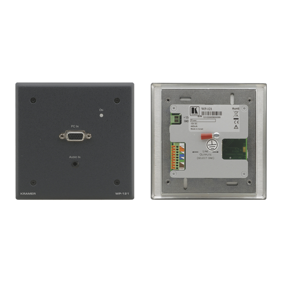
9-Pin TP terminal block LINE OUTPUTS signal from a video RJ-45 TP connector source Table 1 Table 2 refer also to the WP-121 80mm and WP-121 86mm shown below. KRAMER: SIMPLE CREATIVE TECHNOLOGY... -
Page 7: Figure 3: Wp-121 80/86Mm Front Panel
Defining the WP-121 XGA/Unbalanced Stereo Audio Line Transmitter Figure 3: WP-121 80/86mm Front Panel Figure 4: WP-121 80/86mm Rear Panel... -
Page 8: Installing And Connecting The Wp-121
TP receiver —or— RJ-45 line output of the WP-121 to the pre-installed STP wiring in the wall box opening that connects to the TP receiver 2. Recommended—ground the wall plate (see Section 5.3). -
Page 9: Connecting The Wp-121
2. Insert the M3x6 screw through the toothed lock washers and the ring-tongue terminal in the order shown above. 3. Insert the M3x6 screw (with the two toothed lock washers and ring-tongue terminal in place) into the grounding screw hole on the rear of the WP-121 and tighten the screw. -
Page 10: Wiring The Tp Line Output Connectors
Installing and Connecting the WP-121 5.4 Wiring the TP Line Output Connectors 5.4.1 Wiring the RJ-45 Line Output Connector Table 4 Figure 7 define the STP pinout using a straight through cable with RJ-45 connectors. Connect/solder the cable shield to the connector shield. -
Page 11: Capturing The Edid
Capturing the EDID 6 Capturing the EDID The EDID can either be captured automatically by the WP-121 transmitter, or you can set it manually with one of the preconfigured values (see Table Figure 9: WP-121 PCB Assembly Front View with Face Plate Removed... -
Page 12: Setting A Preconfigured Edid
The EDID status LED flashes slowly several times. The new EDID is captured when the LED stops flashing and lights solid. 6. Unplug the power adapter from the mains and disconnect it from the WP-121. 7. Replace the faceplate and secure the four screws removed in Step 1. -
Page 13: Technical Specifications
Technical Specifications 7 Technical Specifications lists the technical specifications of the WP-121. Table 7 Table 7: Technical Specifications of the WP-121 INPUTS: 1 UXGA on a 15-pin HD (F) connector 1 Unbalanced stereo audio on a 3.5mm mini jack 1 Power 12V DC on 2-pin removable terminal block... - Page 14 EXCLUSION OF DAMAGES The liability of Kramer for any effective products is limited to the repair or replacement of the product at our option. Kramer shall not be liable for: 1. Damage to other property caused by defects in this product, damages based upon inconvenience, loss of use of the product, loss of time, commercial loss;...
- Page 15 For the latest information on our products and a list of Kramer distributors visit www.kramerelectronics.com where updates to this user manual may be found. We welcome your questions, comments and feedback. Safety Warning: Disconnect the unit from the power supply before opening/servicing.
Need help?
Do you have a question about the WP-121 and is the answer not in the manual?
Questions and answers