
Subscribe to Our Youtube Channel
Related Manuals for Kramer SID-X1N


Summary of Contents for Kramer SID-X1N
- Page 1 KR AM E R E LE CT RO NI C S LT D. USER MANUAL MODEL: SID-X1N Step-in Commander P/N: 2900-300302 Rev 5...
-
Page 4: Table Of Contents
Kramer Protocol 2000 Instruction Codes 12.3 RS-232 Hardware Interface Figures Figure 1: SID-X1N Step-in Commander Front Panel Figure 2: SID-X1N Step-in Commander Rear Panel Figure 3: Connecting the SID-X1N Step-in Commander Figure 4: Remote Step-In Switch and LED Wiring Figure 5: Remote Select Switch and LED Wiring... -
Page 5: Introduction
Introduction Welcome to Kramer Electronics! Since 1981, Kramer Electronics has been providing a world of unique, creative, and affordable solutions to the vast range of problems that confront video, audio, presentation, and broadcasting professionals on a daily basis. In recent years, we have redesigned and upgraded most of our... -
Page 6: Getting Started
Avoid interference from neighboring electrical appliances that may adversely influence signal quality • Position your Kramer SID-X1N away from moisture, excessive sunlight and dust This equipment is to be used only inside a building. It may only be connected to other equipment that is installed inside a building. -
Page 7: About The Power Connect Plus™ Feature
About the Power Connect Plus™ Feature The Power Connect Plus™ feature means that only the SID-X1N needs to be connected to a power source when the SID-X1N and receiver are within 60m (197ft) of each other. The Power Connect Plus™ feature applies as long as the cable can carry power and the distance does not exceed 60m on standard TP cable. -
Page 8: Overview
DGKat receiver, (for example, the VP-81SIDN or PT-572+). The SID-X1N also provides an unbalanced, stereo audio output. When the SID-X1N is connected to a switcher, it also controls the input and output selection of the switcher. In particular the SID-X1N: features: •... - Page 9 Support for digital audio formats • ® A MegaTOOLS sized enclosure. Two devices can be mounted in a rack using the optional RK-T2B adapter You can control the SID-X1N using the front panel buttons or remotely via contact closure switches. SID-X1N - Overview...
-
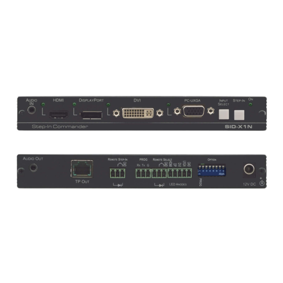
Page 10: Defining The Sid-X1N Step-In Commander
Defining the SID-X1N Step-in Commander Figure 1 defines the front panel of the SID-X1N. Figure 1: SID-X1N Step-in Commander Front Panel Feature Function AUDIO IN 3.5mm Mini Jack Connect to an unbalanced stereo audio source Lights green when the HDMI input is selected... -
Page 11: Figure 2: Sid-X1N Step-In Commander Rear Panel
Figure 2 defines the rear panel of the SID-X1N. Figure 2: SID-X1N Step-in Commander Rear Panel Feature Function AUDIO OUT 3.5mm Mini Jack Connect to an unbalanced, stereo audio acceptor, (see Section TP OUT RJ-45 Connector Connect to a compatible switcher or DGKat receiver, (for... -
Page 12: Connecting The Sid-X1N
Connecting the SID-X1N Switch off the power to all devices before connecting them to your SID-X1N. After connecting your SID-X1N connect the power to other devices. Figure 3: Connecting the SID-X1N Step-in Commander To connect the SID-X1N as illustrated in Figure 1. -
Page 13: Connecting The Remote Step-In Switch And Led
LEDs (see Section 5.3). 8. Connect the power adapter to the SID-X1N and to the mains power. Note: All LED supplies include a current limiting resistor and are designed to work with any standard LED. Connecting the Remote Step-In Switch and LED... -
Page 14: Connecting The Remote Select Switch And Led
You can connect a remote, contact closure, input selection switch to activate an input (momentary contact is sufficient to switch inputs), as well as an indicator LED to the terminal block on the rear panel of the SID-X1N. Figure 5 illustrates the connections from the terminal block to the switch and LED. -
Page 15: Connecting The Remote Input Selection Leds
Connecting the Remote Input Selection LEDs You can connect remote, input selection LEDS to the LED terminal block on the rear panel of the SID-X1N to indicate which is the active input. Figure 6 illustrates the connections from the terminal block to the LEDs. -
Page 16: Principles Of Operation
In manual mode the input is selected using the front panel buttons. Only inputs with a live signal present can be selected. In last connected mode the SID-X1N selects the input based on which input was connected last. If the signal on this input is subsequently lost for any reason, the input with a live signal with the highest priority is automatically selected. -
Page 17: Audio Signal Control
Embedded DVI Inserted/Not inserted 3.5mm mini jack Automatic Output Shutdown The SID-X1N can disable the output (signal and 5V) when there is no signal for a specified period in: • Manual mode—when the signal on the currently selected input is lost •... -
Page 18: Operating The Sid-X1N
Powering up the SID-X1N recalls from the non-volatile memory the last settings that were in force when the device was powered down. The SID-X1N inputs can be selected remotely via the VP-81SIDN. For details on how to do so, see the VP-81SIDN User Manual. -
Page 19: Taking Control Of The Switcher Input
Taking Control of the Switcher Input To activate the input of the switcher to which the SID-X1N is connected, press the STEP-IN button. If the switcher grants the SID-X1N access to the input, the STEP- IN button lights. If the switcher does not grant access for some reason, the button flashes for a few seconds and then does not light. -
Page 20: Configuring And Maintaining The Sid-X1N
Sets the video input selection On—Last connected selection mode to either last connected Off—Manual or manual, (see Section 6.1) Lock EDID Locks the current EDID, (see On—Locked EDID Section 7.3) Off—Automatic EDID selection SID-X1N - Configuring and Maintaining the SID-X1N... - Page 21 Off—Power is disabled when input lost signal is lost after delay set by DIP- switch 7 Note: DIP-switch 2 must be set to ON to enable DIP-switch 3 to control the DVI audio mode selection. SID-X1N - Configuring and Maintaining the SID-X1N...
-
Page 22: Wiring The Twisted Pair Rj-45 Connectors
Brown Pair 1 4 and 5 Pair 2 1 and 2 Pair 3 3 and 6 Using a TP cable that is incorrectly wired will cause Warning: permanent damage to the device SID-X1N - Wiring the Twisted Pair RJ-45 Connectors... -
Page 23: Technical Specifications
18.8cm x 11.3cm x 2.5cm (7.4” x 4.5” x 1”) W, D, H rack- mountable WEIGHT: 0.48kg (1.1lbs) approx. INCLUDED Power adapter ACCESSORIES: OPTIONS: 19“ Rack adapter RK-T2B, RTBUS-12, RTBUS-22, SID-X1NBP Kit (substitute black top plate for the SID-X1N to blend in with the color of the modular TBUS-10xl) SID-X1N - Technical Specifications... -
Page 24: Supported Resolutions
1366 x 768 60Hz; 1280 x 960 60Hz 1280 x 1024p 75Hz; 60Hz 1440 x 900p 60Hz 1400 x 1050 60Hz 1600 x 900p 60Hz 1680 x 1050p 60Hz 1600 x 1200p 60Hz 1080 x 1920i 60Hz; SID-X1N - Technical Specifications... - Page 25 1152 x 864 75Hz 1360 x 768 60Hz; 1366 x 768 60Hz; 50Hz 1280 x 960p 60Hz 1280 x 1024p 60Hz 1440 x 900 60Hz 1400 x 1050 60Hz 1920 x 1080p 60Hz 1920 x 1200 60Hz; 50Hz SID-X1N - Technical Specifications...
-
Page 26: Default Edid
Default EDID Each input on the SID-X1N is loaded with a factory default EDID. Note: When the SID-X1N is connected to a DVI acceptor, an audio block is added to the EDID. 11.1 HDMI, DisplayPort and DVI Monitor Model name....SID-X1N Manufacturer..... - Page 27 Front center..... No Rear left/right..No Rear center....No Front left/right center.. No Rear left/right center... No Rear LFE....No Report information Date generated... 06/08/2014 Software revision..2.60.0.972 Data source....File Operating system..6.1.7601.2.Service Pack 1 SID-X1N - Default EDID...
-
Page 28: Pc-Uxga
1024 x 768p at 75Hz - VESA 1280 x 1024p at 75Hz - VESA 1152 x 870p at 75Hz - Apple Mac II 1280 x 1024p at 75Hz - VESA STD 1280 x 1024p at 85Hz - VESA STD SID-X1N - Default EDID... - Page 29 1152 x 864p at 70Hz - VESA STD 1280 x 960p at 60Hz - VESA STD Report information Date generated... 11/02/2015 Software revision..2.60.0.972 Data source....File Operating system..6.1.7601.2.Service Pack 1 Raw data 00,FF,FF,FF,FF,FF,FF,00,2D,B2,72,06,02,00,00,00,FF,15,01,03,6E,34,20,78,EE,B3,25,AC,51,30,B4,26, 10,50,54,FF,FF,80,81,8F,81,99,A9,40,61,59,45,59,31,59,71,4A,81,40,01,1D,00,72,51,D0,1E,20,6E,28, 55,00,07,44,21,00,00,1E,00,00,00,FF,00,35,30,35,2D,37,30,39,39,39,30,31,30,30,00,00,00,FC,00,53, 49,44,2D,58,31,4E,00,00,00,00,00,00,00,00,00,FD,00,38,4C,1E,53,11,00,0A,20,20,20,20,20,20,00,41, FF,FF,FF,FF,FF,FF,FF,FF,FF,FF,FF,FF,FF,FF,FF,FF,FF,FF,FF,FF,FF,FF,FF,FF,FF,FF,FF,FF,FF,FF,FF,FF, FF,FF,FF,FF,FF,FF,FF,FF,FF,FF,FF,FF,FF,FF,FF,FF,FF,FF,FF,FF,FF,FF,FF,FF,FF,FF,FF,FF,FF,FF,FF,FF, FF,FF,FF,FF,FF,FF,FF,FF,FF,FF,FF,FF,FF,FF,FF,FF,FF,FF,FF,FF,FF,FF,FF,FF,FF,FF,FF,FF,FF,FF,FF,FF, FF,FF,FF,FF,FF,FF,FF,FF,FF,FF,FF,FF,FF,FF,FF,FF,FF,FF,FF,FF,FF,FF,FF,FF,FF,FF,FF,FF,FF,FF,FF,FF SID-X1N - Default EDID...
-
Page 30: Remote Commands
Remote Commands Note: The SID-X1N can be controlled remotely only via DGKat, for example from the VP-81SID or TP-574, using Kramer Protocol 2000 remote commands. This protocol uses four bytes of information as defined below. The default data rate is 9600 baud, with no parity, 8 data bits and 1 stop bit. -
Page 31: Kramer Protocol 2000 Instruction Codes
When a single machine is controlled over the serial port, always set M4…M0 to 1, and make sure that the machine itself is configured as MACHINE NUMBER = 1. 12.2 Kramer Protocol 2000 Instruction Codes All the values in the table are decimal, unless otherwise stated Instruction Codes for Commands... -
Page 32: Rs-232 Hardware Interface
8 data bits and 1 stop bit. Note: Using any additional, non-standard RS-232 commands developed for internal debugging purposes is not recommended. Such commands are only used internally for performing firmware upgrades over the RS-232 hardware interface. SID-X1N - Remote Commands... - Page 34 For the latest information on our products and a list of Kramer distributors, visit our Web site where updates to this user manual may be found. S A F E T Y W A R N IN G D is c o n n e c t t h e u n it fr o m t h e p o w e r...
Need help?
Do you have a question about the SID-X1N and is the answer not in the manual?
Questions and answers