
Subscribe to Our Youtube Channel
Related Manuals for Kramer WP-121


Summary of Contents for Kramer WP-121
- Page 1 K R A ME R E LE CT R O N IC S L T D . USER MANUAL MODEL: WP-121 XGA/Unbalanced Stereo Audio Line Transmitter P/N: 2900-000622 Rev 5...
-
Page 2: Table Of Contents
Figure 3: WP-121 Rear Panel (80/86mm) Figure 4: Installing and Connecting the WP-121 Figure 5: Ground Connection Figure 6: TP PINOUT Figure 7: Terminal Block Pinouts Figure 8: WP-121 PCB Assembly Front View with Face Plate Removed WP-121 – Contents... -
Page 3: Introduction
This user manual Download up-to-date Kramer user manuals from our Web site at http://www.kramerelectronics.com All references to WP-121 in this manual refer to the US version (69mm) as well as to the WP-121 80mm and WP-121 86mm European versions. WP-121 - Introduction... -
Page 4: Getting Started
Do not secure the cables in tight bundles or roll the slack into tight coils • Avoid interference from neighboring electrical appliances that may adversely influence signal quality • Position your Kramer WP-121 away from moisture, excessive sunlight and dust WP-121 - Getting Started... -
Page 5: Overview
Overview The Kramer WP-121 wall plate is a line transmitter that accepts a UXGA video and an unbalanced stereo audio signal, encodes them to a twisted pair (TP) signal and transmits the TP signal to a compatible TP receiver. For example, the Kramer TP-122/N or TP-122-od. -
Page 6: Shielded Twisted Pair (Stp)/Unshielded Twisted Pair (Utp)
EDID is defined by a standard published by the Video Electronics Standards Association (VESA). The WP-121 is supplied with a default EDID but it can also store and recall EDID data in non-volatile memory, allowing convenient and reliable connection to the source. -
Page 7: Defining The Wp-121
Defining the WP-121 Figure 1 defines the WP-121. Figure 1: WP-121 US Version (69mm) Feature Function AUDIO IN 3.5mm Mini Jack Connect to an unbalanced stereo audio source PC IN XGA 15-Pin HD (F) Connect to the XGA source Connector... -
Page 8: Figure 2: Wp-121 Front Panel (80/86Mm)
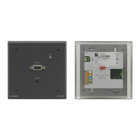
Figure 2 Figure 3 define the WP-121 front and rear panels, respectively, for the European 80mm and 86mm versions. Figure 2: WP-121 Front Panel (80/86mm) Figure 3: WP-121 Rear Panel (80/86mm) Feature Function AUDIO IN 3.5mm Mini Jack Connect to an unbalanced stereo audio source... -
Page 9: Installing And Connecting The Wp-121
Connect the wire labeled “+” to the +12V pin, and the wire labeled “–” to the GND pin. 4. Insert the WP-121 into the wall box opening and secure the WP-121 front panel using the screws. -
Page 10: Grounding The Wall Plate
2. Insert the M3x6 screw through the toothed lock washers and the ring-tongue terminal in the order shown above. 3. Insert the M3x6 screw (with the two toothed lock washers and ring-tongue terminal in place) into the grounding screw hole on the rear of the WP-121 and tighten the screw. Item... -
Page 11: Wiring The Tp Line In / Line Out Rj-45 Connectors
Note, that the cable Ground shielding must be connected / soldered to the connector shield. Figure 6: TP PINOUT EIA /TIA 568B Wire Color Orange / White Orange Green / White Blue Blue / White Green Brown / White Brown WP-121 - Installing and Connecting the WP-121... -
Page 12: Wiring The 9-Pin Terminal Block Line Output Connector
Use the connector clips only when removing wires, not when inserting them • Each wire should protrude 9mm (0.35") from the plastic insulation so that it can be easily connected. To prevent the wires crossing, be sure that each wire is fully inserted WP-121 - Installing and Connecting the WP-121... -
Page 13: Capturing The Edid
Capturing the EDID The EDID can either be captured automatically by the WP-121 transmitter, or you can set it manually with one of the preconfigured values (see Section Figure 8: WP-121 PCB Assembly Front View with Face Plate Removed Feature... -
Page 14: Capturing The Edid From A Display Device
PCB assembly. 2. Using a short cable (for example, Kramer model number C-MGM/MGM-1), connect the PC IN input 15-pin HD connector on the WP-121 to the XGA connector of the display and turn the display on. 3. Ensure that the rotary switch (see Figure 8) is in position 0. - Page 15 (Default) 800x600 60Hz 1440x1050 60Hz 1024x768 60Hz 1600x1200 60Hz 1152x864 75Hz 1680x1050 60Hz 1280x720 60Hz 1920x1080 60Hz 1280x800 60Hz 1920x1200 60Hz 1024x1024 60Hz For future use 1360x768 60Hz For future use WP-121 - Capturing the EDID from a Display Device...
-
Page 16: Technical Specifications
1.4" x 4.49", W, D, H) 2 gang for Europe: 15.2cm x 3.5cm x 8.0/8.6cm (5.98" x 1.4" x 3.15/3.39", W, D, H) WEIGHT: 0.14kg (0.31lbs) approx. ACCESSORIES: Power adapter Specifications are subject to change without notice at http://www.kramerelectronics.com WP-121 - Technical Specifications... - Page 18 For the latest information on our products and a list of Kramer distributors, visit our Web site where updates to this user manual may be found. We welcome your questions, comments, and feedback. Web site: www.kramerelectronics.com E-mail: info@kramerel.com SAFETY WARNING...
Need help?
Do you have a question about the WP-121 and is the answer not in the manual?
Questions and answers