Table of Contents
Advertisement
Advertisement
Table of Contents

Subscribe to Our Youtube Channel
Related Manuals for Kramer TP-104


Summary of Contents for Kramer TP-104
- Page 1 Kramer Electronics, Ltd. Preliminary USER MANUAL Models: TP-104, TP-104HD, XGA Line Transmitter/DA TP-105, TP-105(HD), CAT 5 Line Driver/DA TP-121, XGA/Audio Line Transmitter TP-122, XGA/Audio Line Receiver TP-123, XGA/Audio/Data Line Transmitter TP-124, XGA/Audio/Data Line Receiver...
-
Page 2: Table Of Contents
Configuring a 1:4 XGA to TP Transmitter/Receiver/DA Configuring a TP-105 CAT 5 Line Driver/DA Technical Specifications Figures Figure 1: TP-104 XGA Line Transmitter/DA Figure 2: TP-104HD XGA Line Transmitter/DA Figure 3: TP-104 (Underside Panel) Figure 4: TP-105 CAT 5 Line Driver/DA... - Page 3 Table 11: TP-124 XGA/Audio/Data Line Receiver (Underside) Features Table 12: CAT 5 PINOUT Table 13: RS-232 PINOUT Connection Table 14: Technical Specifications of the TP-104 and the TP-104HD Table 15: Technical Specifications of the TP-105 and the TP-105(HD) Table 16: Technical Specifications of the TP-121/TP-122/TP-123/TP-124...
-
Page 4: Introduction
Scan Converters and Scalers; GROUP 8: Cables and Connectors; GROUP 9: Room Connectivity; GROUP 10: Accessories and Rack Adapters; GROUP 11: Sierra Products 2 Download up-to-date Kramer user manuals at http://www.kramerelectronics.com 3 The complete list of Kramer cables is on our Web site at http://www.kramerelectronics.com... -
Page 5: Quick Start
Getting Started Quick Start This quick start chart summarizes the basic setup and operation steps. KRAMER: SIMPLE CREATIVE TECHNOLOGY... - Page 6 Getting Started...
-
Page 7: Overview
We recommend that you use Shielded Twisted Pair (STP) cable. There are different levels of STP cable available, and we advise you to use the best quality STP cable that you can afford. Our non-skew-free cable, Kramer BC-STP is intended for analog signals where skewing is not an issue. For cases where there is skewing, our UTP skew-free cable, Kramer BC-XTP, may be used. -
Page 8: About The Power Connect Feature
Kramer product away from moisture, excessive sunlight and dust 1 CAT 5 cable is still suitable for the video/audio transmission, but not for feeding the power at these distances 2 Available from Kramer Electronics on our Web site at http://www.kramerelectronics.com... -
Page 9: Your Tp-104/Tp-104Hd Xga Line Transmitter/Da
Figure 1: TP-104 XGA Line Transmitter/DA Figure 2: TP-104HD XGA Line Transmitter/DA 1 The TP-104HD is similar to the TP-104 but can also receive HD signals (high definition resolutions: 480p, 576p, 720p, 1080i and 1080p) 2 The terminology XGA is used throughout this manual, where this implies any RGBHV signal on a 15-pin HD (F) -
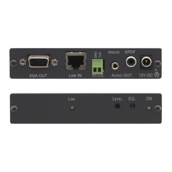
Page 10: Figure 3: Tp-104 (Underside Panel)
Your TP-104/TP-104HD XGA Line Transmitter/DA Table 1: TP-104, TP-104HD XGA Line Transmitter/DA Features Feature Function 12V DC +12V DC connector for powering the unit OUT 4 RJ-45 connector Connects to the LINE IN RJ-45 connector on the TP-122 XGA/Audio Line... -
Page 11: Your Tp-105/Tp-105(Hd) Cat 5 Line Driver/Da
2 Using a UTP CAT 5 cable with RJ-45 connectors at both ends (the PINOUT is defined in Table 12 Figure 3 Insert a screwdriver into the hole and carefully rotate it, to trim the level KRAMER: SIMPLE CREATIVE TECHNOLOGY... -
Page 12: Your Tp-121/Tp-122
Your TP-121/TP-122 Your TP-121/TP-122 This section defines the TP-121 XGA/Audio Line Transmitter (see section 6.1), and the TP-122 XGA/Audio Line Receiver (see section 6.2). Your TP-121 XGA/Audio Line Transmitter The TP-121 is an XGA/audio stereo line transmitter that receives an XGA signal and an unbalanced stereo analog audio signal and transmits them over CAT 5 cable to a TP-122 receiver, converting the unbalanced stereo analog audio signal to digital audio (S/PDIF) stream before transmitting,... -
Page 13: 6.1.1 The Tp-121 Internal Polarity Switches
300ft (more than 100m) over standard CAT 5 cable. 1 By default, both switches are set down (for a negative V SYNC and H SYNC polarity) 2 The underside is identical on the TP-122 and TP-124 KRAMER: SIMPLE CREATIVE TECHNOLOGY... -
Page 14: Figure 7: Tp-122 Xga/Audio Line Receiver (Topside)
1 Using a UTP CAT 5 cable with RJ-45 connectors at both ends (the PINOUT is defined in Table 12 Figure 2 The TP-104 does not accept the audio signals 3 Degradation and VGA/XGA signal loss can result from using long cables (due to stray capacitance), sometimes leading to a total loss of sharpness in high-resolution signals... -
Page 15: Your Tp-122 Xga/Audio Line Receiver (Underside)
H SYNC to negative polarity 1 The underside is identical on the TP-122 and TP-124 2 By default, both switches are set down (for a negative V SYNC and H SYNC polarity) KRAMER: SIMPLE CREATIVE TECHNOLOGY... -
Page 16: Your Tp-123/Tp-124
Your TP-123/TP-124 Your TP-123/TP-124 This section describes the TP-123 XGA/Audio/Data Line Transmitter (see section 7.1), and the TP-124 XGA/Audio/Data Line Receiver (see section 7.2). Your TP-123 XGA/Audio/Data Line Transmitter The TP-123 is a high-performance transmitter that accepts a computer graphics input signal, an unbalanced stereo analog audio signal, unidirectional (RxD) RS-232 control commands and 12V DC power, over CAT 5 cable, and transmits to a TP-124 receiver. -
Page 17: 7.1.1 The Tp-123 Internal Polarity Switches
1 Using a UTP CAT 5 cable with RJ-45 connectors at both ends (the PINOUT is defined in Table 12 Figure 2 By default, both switches are set down (for a negative V SYNC and H SYNC polarity) KRAMER: SIMPLE CREATIVE TECHNOLOGY... -
Page 18: Your Tp-124 Xga/Audio/Data Line Receiver
Your TP-124 XGA/Audio/Data Line Receiver The TP-124 is a high-performance receiver obtaining the computer graphics signal/audio/control data from the Kramer TP-123 via UTP cabling at its CAT 5 Line input. The TP-124 outputs a computer graphics signal, an unbalanced stereo analog audio signal, a converted digital audio (S/PDIF) signal and RS-232 control commands. -
Page 19: Your Tp-124 Xga/Audio/Data Line Receiver (Underside)
1 Using a UTP cable with CAT 5 connectors at both ends (the PINOUT is defined in Table 12 Figure 2 The TP-104 does not accept the audio signals 3 Degradation and VGA/XGA signal loss can result from using long cables (due to stray capacitance), sometimes leading to a total loss of sharpness in high-resolution signals... -
Page 20: Connecting The Xga/Audio Line Transmitter/Receiver
, on the underside 1 Not supplied. The complete list of Kramer cables is on our Web site at http://www.kramerelectronics.com 2 If you cannot connect the power to both the TP-121 and TP-122, you can just connect the power to the TP-122... - Page 21 Connecting the XGA/Audio Line Transmitter/Receiver Figure 13: Connecting the XGA/Audio Line Transmitter/Receiver System KRAMER: SIMPLE CREATIVE TECHNOLOGY...
-
Page 22: Wiring The Cat 5 Line In/Line Out Rj-45 Connectors
2 PIN terminal block connector at the other end to 1 Not supplied. The full list of Kramer cables is on our Web site at http://www.kramerelectronics.com. Alternatively, you can connect an XGA source to the XGA IN 15-pin HD (F) connector, and a separate audio source to the AUDIO IN 3.5mm mini... - Page 23 3 If you cannot connect the power to both the TP-123 and TP-124, you can just connect the power to any one unit 4 Use a screwdriver to carefully rotate the trimmer, adjusting the appropriate level 5 By default, both switches are set down (for negative V SYNC and H SYNC polarity) KRAMER: SIMPLE CREATIVE TECHNOLOGY...
- Page 24 Connecting the XGA/Audio/Data Line Transmitter/Receiver Figure 15: Connecting the XGA/Audio/Data Line Transmitter/Receiver System...
-
Page 25: Controlling Via Rs-232 (For Example, Using A Pc)
PIN terminal block connector at the other end, as defined in Figure 16 Table Figure 16: RS-232 PINOUT Connection Table 13: RS-232 PINOUT Connection Connect this PIN on the To this PIN on the Terminal Block 9-pin D-sub Connector: Connector PIN 2 PIN 3 PIN 5 KRAMER: SIMPLE CREATIVE TECHNOLOGY... -
Page 26: Configuring A 1:4 Xga To Tp Transmitter/Receiver/Da
XGA OUT 15-pin HD (F) connector of Unit IV to the XGA acceptor (for example, Display 4) 3. On each of the five Kramer TOOLS, connect the 12V DC power adapter to the power socket and connect the adapter to the mains electricity. - Page 27 Configuring a 1:4 XGA to TP Transmitter/Receiver/DA Figure 17: Configuring a 1:4 XGA to Twisted Pair Transmitter/Receiver/DA KRAMER: SIMPLE CREATIVE TECHNOLOGY...
-
Page 28: Configuring A Tp-105 Cat 5 Line Driver/Da
XGA OUT 15-pin HD (F) connector on the second TP-120 unit to the XGA acceptor (for example, Display 2) 4. On each of the four Kramer units, connect the 12V DC power adapter to the power socket and connect the adapter to the mains electricity. - Page 29 Configuring a TP-105 CAT 5 Line Driver/DA Figure 18: Configuring a TP-105 CAT 5 Line Driver/DA KRAMER: SIMPLE CREATIVE TECHNOLOGY...
-
Page 30: Technical Specifications
1 Specifications are subject to change without notice 2 With 60m CAT 5 cable 3 For the TP-104 Transmitter/ TP-120 Receiver SETUP 4 The HD resolutions apply to the HD version of the machine 5 For the PT-110 to TP-105 to TP-120 Receiver SETUP... -
Page 31: Table 16: Technical Specifications Of The Tp-121/Tp-122/Tp-123/Tp-124
TP-124 via Power Connect) Connect) DIMENSIONS: 12.1cm x 7.18cm x 2.42cm (4.76" x 2.83" x 0.95") W, D, H WEIGHT: 0.3kg (0.67lbs) approx. ACCESSORIES: Power supply OPTIONS: 19” rack mount 1 For the Transmitter/Receiver pair KRAMER: SIMPLE CREATIVE TECHNOLOGY... - Page 32 EXCLUSION OF DAMAGES The liability of Kramer for any effective products is limited to the repair or replacement of the product at our option. Kramer shall not be liable for: 1. Damage to other property caused by defects in this product, damages based upon inconvenience, loss of use of the product, loss of time, commercial loss;...
- Page 33 For the latest information on our products and a list of Kramer distributors, visit our Web site: www.kramerelectronics.com, where updates to this user manual may be found. We welcome your questions, comments and feedback. Safety Warning: Disconnect the unit from the power supply before opening/servicing.
Need help?
Do you have a question about the TP-104 and is the answer not in the manual?
Questions and answers