Table of Contents
Advertisement
Quick Links
TKS | TKP | TKM
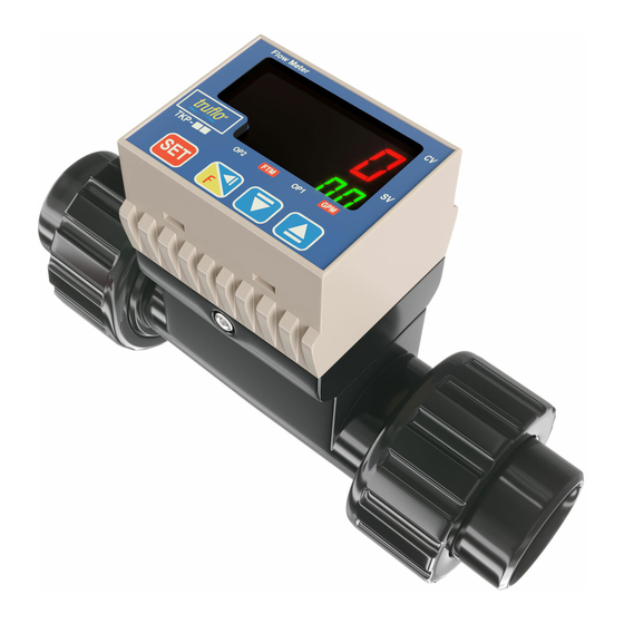
Multi-Function Paddle Wheel Flow Meter
TK SERIES MANUAL
Flow Rate & Totalizer
Password Security Protected
Zirconium Ceramic | Rotor | Bearings
Display Rotates 360 Degrees
Bright LED Display
Read carefully the instructions published in this manual before the first use of the sensor. Keep the manual
at a safe place. The manufacturer reserves the right to implement changes without prior notice
for more information visit www.iconprocon.com
ROTATOR
SERIES MANUAL
Programming
© Icon Process Controls Ltd. All Rights Reserved
Advertisement
Table of Contents

Subscribe to Our Youtube Channel
Summary of Contents for Icon Process Controls truflo TK Series
- Page 1 Read carefully the instructions published in this manual before the first use of the sensor. Keep the manual at a safe place. The manufacturer reserves the right to implement changes without prior notice © Icon Process Controls Ltd. All Rights Reserved for more information visit www.iconprocon.com...
-
Page 2: Table Of Contents
9.2 TKM - (4-20mA or 0-5V DC + NPN Pulse) Flow Rate + Flow Totalizer + Pulse Diagram 9.3 TKS NPN (Flow Rate + Relay + Pulse) Diagram 10. Installation Positions Installation Positions 11. Warranty, Returns and Limitations © Icon Process Controls Ltd. All Rights Reserved for more information visit www.iconprocon.com... -
Page 3: Parts Tk Series
F - ANSI 150 lb 60mA Max Current Draw 6. RS = TKP Series (Only) with RS-485 MODBUS 7. M = M12 - 2 Meters - Quick Disconnect (Option) Battery 10-30VDC © Icon Process Controls Ltd. All Rights Reserved for more information visit www.iconprocon.com... -
Page 4: Procedure To Rotate Display
Range : 0.1 - 999.9 4 mA = 0 20 mA = Entered Number. TR 100 (Default) 4 mA = 0 GPM 20mA =100 GPM Press This can be Change to Conform to Customers Application (Ex. Number Changed to 150) © Icon Process Controls Ltd. All Rights Reserved for more information visit www.iconprocon.com... -
Page 5: Programming Npn Pulse Output Models Tkp | Tkm Only
Program Time Delay for NPN Pulse (OP1) on Initial Start Up Time For Initial Start UP (Sec) Range : 0-9999 (Secs) Time Delay of Pulse Output (Flow Rate) Press T2 = 20 (Secs) (Default) Flow Rate © Icon Process Controls Ltd. All Rights Reserved for more information visit www.iconprocon.com... -
Page 6: Mode Of Npn Pulse Output Tkp | Tkm Models
Range : 0-99 sec Delay Time to Power on Alarm Output Relay Time Delay t.20 (Default) (20 Seconds) Initial Start up of Flow Meter or Process (Allows for System Press Alarm Steady State before Relay Switch becomes Active). © Icon Process Controls Ltd. All Rights Reserved for more information visit www.iconprocon.com... -
Page 7: Programming Tks Model Only Program Relay Set Point And Relay Delay (Prevents Relay Chatter)
Con = F Pulse Output of Paddle = 5 KHZ Max Totalizer Reset TKP | TKM Series Reset Flow Totalizer Zero Press Key Hold 3 sec (PressTogether) © Icon Process Controls Ltd. All Rights Reserved for more information visit www.iconprocon.com... -
Page 8: Standard Pipe Size
Circuit Grey White Black Flow Rate Pulse Output NPN Output NPN Blue Black Wire can be Changed for Flow Total Limit Output or Unit Volume Pulse Output © Icon Process Controls Ltd. All Rights Reserved for more information visit www.iconprocon.com... -
Page 9: Tks Npn (Flow Rate + Relay + Pulse) Diagram
Current output (4 - 20mA) : 120 max. Voltage output (0 - 5V) : 10K min. TKM Series (0-5VDC) Optional 4-20mA is Standard 10. Installation Positions CORRECT INCORRECT CORRECT INCORRECT CORRECT INCORRECT © Icon Process Controls Ltd. All Rights Reserved for more information visit www.iconprocon.com... -
Page 10: Installation Positions
- max 10% Particle Size - Not to Exceed .5mm Cross Section or Length. Please do not flush the pipe after the Flow Meter is installed with Compressed Air this may damage the ceramic shaft and will Void Warranty © Icon Process Controls Ltd. All Rights Reserved for more information visit www.iconprocon.com... -
Page 11: Warranty, Returns And Limitations
Warranty Icon Process Controls Ltd warrants to the original purchaser of its products that such products will be free from defects in material and workmanship under normal use and service in accordance with instructions furnished by Icon Process Controls Ltd for a period of one years from the date of sale of such products.

Need help?
Do you have a question about the truflo TK Series and is the answer not in the manual?
Questions and answers